EP0149555B1 - Racquets - Google Patents
Racquets Download PDFInfo
- Publication number
- EP0149555B1 EP0149555B1 EP85300280A EP85300280A EP0149555B1 EP 0149555 B1 EP0149555 B1 EP 0149555B1 EP 85300280 A EP85300280 A EP 85300280A EP 85300280 A EP85300280 A EP 85300280A EP 0149555 B1 EP0149555 B1 EP 0149555B1
- Authority
- EP
- European Patent Office
- Prior art keywords
- handle
- racquet
- end portions
- frame
- handle member
- Prior art date
- Legal status (The legal status is an assumption and is not a legal conclusion. Google has not performed a legal analysis and makes no representation as to the accuracy of the status listed.)
- Expired - Lifetime
Links
- 230000000295 complement effect Effects 0.000 claims description 4
- XAGFODPZIPBFFR-UHFFFAOYSA-N aluminium Chemical compound [Al] XAGFODPZIPBFFR-UHFFFAOYSA-N 0.000 description 4
- 229910052782 aluminium Inorganic materials 0.000 description 4
- 239000004411 aluminium Substances 0.000 description 4
- 238000003491 array Methods 0.000 description 4
- 239000000463 material Substances 0.000 description 4
- 239000004033 plastic Substances 0.000 description 4
- 229920003023 plastic Polymers 0.000 description 4
- 238000010276 construction Methods 0.000 description 2
- 239000004677 Nylon Substances 0.000 description 1
- 230000000694 effects Effects 0.000 description 1
- 239000010985 leather Substances 0.000 description 1
- 230000004048 modification Effects 0.000 description 1
- 238000012986 modification Methods 0.000 description 1
- 229920001778 nylon Polymers 0.000 description 1
Images


Classifications
-
- A—HUMAN NECESSITIES
- A63—SPORTS; GAMES; AMUSEMENTS
- A63B—APPARATUS FOR PHYSICAL TRAINING, GYMNASTICS, SWIMMING, CLIMBING, OR FENCING; BALL GAMES; TRAINING EQUIPMENT
- A63B49/00—Stringed rackets, e.g. for tennis
- A63B49/02—Frames
-
- A—HUMAN NECESSITIES
- A63—SPORTS; GAMES; AMUSEMENTS
- A63B—APPARATUS FOR PHYSICAL TRAINING, GYMNASTICS, SWIMMING, CLIMBING, OR FENCING; BALL GAMES; TRAINING EQUIPMENT
- A63B60/00—Details or accessories of golf clubs, bats, rackets or the like
- A63B60/06—Handles
- A63B60/22—Adjustable handles
- A63B60/28—Adjustable handles with adjustable length
Definitions
- This invention relates to racquets, and is more particularly but not exclusively concerned with tennis and racquet-ball racquets having an extruded aluminium frame.
- One well-known type of tennis or racquet-ball racquet comprises a substantially oval frame made from a single length of extruded aluminium tubing.
- the tubing is bent to form the oval shape of the frame, and has its opposite ends extending beside and parallel to each other from one end of the major axis of the oval shape of the frame to form the basis or foundation of the handle of the racquet.
- the handle is completed by a suitably shaped sleeve, which slides over and is bonded to the parallel ends of the tubing, while the oval shape of the frame is completed by a throat member, which is secured between the parallel ends of the tubing at the point where they begin to diverge to form the oval shape.
- a racquet of this general type is shown, for example, in US Patent No. 3 931 968.
- a racquet comprises:
- a longitudinal groove is provided in the part of the external surface of the tube which defines the internal periphery of the frame and the facing surfaces of the end portions of the tube, and the sides of the throat member adjacent these facing surfaces are each provided with at least one projecting tab which engages in this groove.
- the racquet-ball racquet illustrated in Figure 1 is indicated generally at 10, and comprises an approximately oval frame 12 made from a single length of extruded aluminium tubing 14, which is bent to form the oval shape of the frame.
- the opposite ends 16, 18 of the tubing 14 extend beside and parallel to each other from one end of the major axis of the oval shape of the frame, to form the basis of a handle 20.
- a plastics handle member 22 fits over the ends 16, 18 of the tubing 14, to secure them together and further define the handle 20, while a plastics throat member 24 is secured between the ends 16, 18 of the tubing 14, at the point where they begin to diverge to form the oval shape of the frame 12, in order to complete the oval shape.
- the handle member 22 and the throat member 24 co-operate in a manner which will be described in more detail hereinafter with reference to Figures 2 to 8.
- the handle 20 of the racquet 10 is completed by covering the handle member 22 with a layer or layers of material whose surface is suitable for gripping, or is covered with a material suitable for gripping, such as leather.
- the racquet 10 also comprises stringing, which is indicated generally at 26 in Figure 1 and is composed of nylon, gut or other suitable stringing material.
- the individual strings of the stringing 26 are secured to the frame 12 by passing them through respective wire string-securing loops, such as those indicated at 28 and 30, which project into the oval space enclosed by the frame 12 from the radially inner surface of the frame.
- the loops 28 project into the space within the frame 12 from the tubing 14; they are formed from a single, suitably-bent, piece of wire, which is secured in a dovetail- section groove in the tubing substantially as described in UK Patent Application No. 83 06050 (Publication No. 2 136 300A).
- the loops 30 project into the space within the frame 12 from the throat member 24, and are preferably moulded into the throat member as described in UK Patent Application No. 83 27851 (Publication No. 2 148 133A).
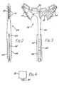
- the plastics throat member 24 is shown in more detail in Figures 2 to 4, from which it can be seen that the throat member comprises a main body 32, which is shaped to slot into the V-shaped space defined between the portions of the tubing 14 at the point where they begin to diverge from the end portions 16,18 to define the oval shape of the frame.
- the sides of the body 32 are provided with projecting tabs 34, which are slotted (to make them resiliently compressible) and barbed, as shown in Figure 4, so that they can be pushed into, and can lock in, the aforementioned dovetail-shaped groove in the tubing 14.
- the loops 30 projecting from the throat member 24 are also formed from a single, suitably-bent, piece of wire, which is moulded into the body 32 as shown at 36.
- ratchet member 40 Projecting downwardly from the centre of the throat member 24, parallel to and between the ends 16, 18 of the tubing 14, is an integrally- moulded elongate double ratchet member 40 of approximately rectangular cross-section.
- the two opposite sides of the ratchet member 40 which face respective ones of the ends 16, 18 of the tubing 14 are provided with identical elongated projecting tabs 42, which engage in the aforementioned dovetail-shaped groove in the tubing.
- the other two opposite sides of the ratchet member 40 i.e. the two sides which face perpendicularly away from the plane of the racquet 10, are provided with respective identical linear arrays of ratchet teeth 44, which are inclined (or biased) towards the main body 32 of the throat member 24.
- the plastics handle member 22 is shown in more detail in Figures 5 tQ 8.
- the handle member 22 comprises an annular flange 50 shaped to be a sliding fit over the ends 16, 18 of the tubing 14, an end socket 52 axially aligned with the flange 50 and shaped to receive the ends 16,18 of the tubing 14, and two parallel connecting members 54 which are moulded integrally with the flange 50 and the end socket 52, and serve to connect them together and hold them in alignment.
- the inner surfaces of the connecting members 54 face into the space between the ends 16, 18 of the tubing 14 from the opposite sides of this space, and are provided with respective linear arrays of ratchet teeth 56.
- the tooth arrays 56 extend parallel to and are aligned with the tooth arrays 44 on the ratchet member 40 of the throat member 24, and the teeth 56 and 44 are complementary to each other.
- the handle member 22 is fitted to the remainder of the racquet 10 by fitting the flange 50 over the ends 16, 18 of the tubing 14 and the extremity of the ratchet member 40 on the throat 24.
- the handle member 22 is pushed further onto the ends 16, 18 of the tubing 14, the extremity of the ratchet member 40 enters the space between the connecting members 54, and the teeth 56 on the latter start to slide in a ratchet-like manner over the teeth 44 on the former.
- the handle member 22 is pushed home until the extremities of the ends 16, 18 of the tubing 14 are fully received in the socket 52, at which point the teeth 44 and 56 are fully engaged.
- the handle 20 of the racquet 10 is then completed as described earlier.
- the interlocking of the handle member 22 and the throat member 24 produces a very strong racquet.
- the throat member is very firmly locked in its proper position between the ends 16, 18 of the tubing 14 at the point where they begin to diverge.
- the handle 20 is very firmly locked in its proper position on the ends 16, 18 of the tubing 14.
- the handle member 22 and the throat member 24 therefore provide a self-locking and self-locating form of construction for the racquet 10.
- this construction requires no holes at all to be provided in the tubing 14 for the securing of the handle member 22 and the throat member 24 thereto.
- tubing 14 can be drawn rather than extruded, and made from materials other than aluminium.
- stringing 26 can be secured to the frame 12 in ways other than that described, for example as described in UK Patent Application No. 82 00 722 (Publication No. 2 094 643).
Landscapes
- Health & Medical Sciences (AREA)
- General Health & Medical Sciences (AREA)
- Physical Education & Sports Medicine (AREA)
- Mutual Connection Of Rods And Tubes (AREA)
Description
- This invention relates to racquets, and is more particularly but not exclusively concerned with tennis and racquet-ball racquets having an extruded aluminium frame.
- One well-known type of tennis or racquet-ball racquet comprises a substantially oval frame made from a single length of extruded aluminium tubing. The tubing is bent to form the oval shape of the frame, and has its opposite ends extending beside and parallel to each other from one end of the major axis of the oval shape of the frame to form the basis or foundation of the handle of the racquet. The handle is completed by a suitably shaped sleeve, which slides over and is bonded to the parallel ends of the tubing, while the oval shape of the frame is completed by a throat member, which is secured between the parallel ends of the tubing at the point where they begin to diverge to form the oval shape. A racquet of this general type is shown, for example, in US Patent No. 3 931 968.
- It is an object of the present invention to provide an improved racquet of this general type.
- According to the present invention, a racquet comprises:
- a handle, a string-supporting frame having two end portions which converge toward said handle and extend longitudinally therethrough, and a throat member disposed between the converging sections of said end portions. The racquet is characterised by a handle structure comprising an internal handle member connected to said throat member, projecting into said handle between said end portions, and having a series of longitudinally arranged ratchet teeth; and an external handle member telescopingly received on said end portions and having a series of longitudinally arranged ratched teeth which are complementary to and cooperate with the ratchet teeth on said internal handle member, whereby the handle is assembled by pushing said external handle member longitudinally onto said end portions so that said cooperating ratchet teeth progressively engage to lock the handle members together and firmly secure said throat member and said frame to the handle.
- Thus the co-operating teeth on the internal handle member connected to the throat member and on the external handle member together produce a kind of ratchet action, which locks the handle member on the end portions of the tube and tends to pull the throat member down between these end portions. This considerably enhances the structural integrity of the racquet.
- In a preferred embodiment of the invention, a longitudinal groove is provided in the part of the external surface of the tube which defines the internal periphery of the frame and the facing surfaces of the end portions of the tube, and the sides of the throat member adjacent these facing surfaces are each provided with at least one projecting tab which engages in this groove.
- Thus the pulling effect resulting from the aforementioned ratchet action tends to lock these tabs more firmly in the groove.
- The invention will now be described, by way of example only, with reference to the accompanying drawings, of which:
- Figure 1 shows a racquet in accordance with the present invention;
- Figure 2 is a side view of a throat member forming part of the racquet of Figure 1;
- Figure 3 is a plan view, partly in section, of the throat member of Figure 2;
- Figure 4 is a view of a detail of the throat member of Figure 2;
- Figure 5 is a plan view, partly in section, of part of the handle of the racquet of Figure 1;
- Figure 6 is a sectional side view of the handle part of Figure 5; and
- Figures 7 and 8 are views of the opposite ends of the handle part of Figures 5 and 6.
- The racquet-ball racquet illustrated in Figure 1 is indicated generally at 10, and comprises an approximately
oval frame 12 made from a single length of extrudedaluminium tubing 14, which is bent to form the oval shape of the frame. Theopposite ends tubing 14 extend beside and parallel to each other from one end of the major axis of the oval shape of the frame, to form the basis of ahandle 20. Aplastics handle member 22 fits over theends tubing 14, to secure them together and further define thehandle 20, while aplastics throat member 24 is secured between theends tubing 14, at the point where they begin to diverge to form the oval shape of theframe 12, in order to complete the oval shape. Thehandle member 22 and thethroat member 24 co-operate in a manner which will be described in more detail hereinafter with reference to Figures 2 to 8. Thehandle 20 of the racquet 10 is completed by covering thehandle member 22 with a layer or layers of material whose surface is suitable for gripping, or is covered with a material suitable for gripping, such as leather. - The racquet 10 also comprises stringing, which is indicated generally at 26 in Figure 1 and is composed of nylon, gut or other suitable stringing material. The individual strings of the stringing 26 are secured to the
frame 12 by passing them through respective wire string-securing loops, such as those indicated at 28 and 30, which project into the oval space enclosed by theframe 12 from the radially inner surface of the frame. As can be seen in Figure 1, theloops 28 project into the space within theframe 12 from thetubing 14; they are formed from a single, suitably-bent, piece of wire, which is secured in a dovetail- section groove in the tubing substantially as described in UK Patent Application No. 83 06050 (Publication No. 2 136 300A). Similarly, theloops 30 project into the space within theframe 12 from thethroat member 24, and are preferably moulded into the throat member as described in UK Patent Application No. 83 27851 (Publication No. 2 148 133A). - The
plastics throat member 24 is shown in more detail in Figures 2 to 4, from which it can be seen that the throat member comprises amain body 32, which is shaped to slot into the V-shaped space defined between the portions of thetubing 14 at the point where they begin to diverge from theend portions body 32 are provided with projectingtabs 34, which are slotted (to make them resiliently compressible) and barbed, as shown in Figure 4, so that they can be pushed into, and can lock in, the aforementioned dovetail-shaped groove in thetubing 14. Theloops 30 projecting from thethroat member 24 are also formed from a single, suitably-bent, piece of wire, which is moulded into thebody 32 as shown at 36. - Projecting downwardly from the centre of the
throat member 24, parallel to and between theends tubing 14, is an integrally- moulded elongatedouble ratchet member 40 of approximately rectangular cross-section. The two opposite sides of theratchet member 40 which face respective ones of theends tubing 14 are provided with identicalelongated projecting tabs 42, which engage in the aforementioned dovetail-shaped groove in the tubing. The other two opposite sides of theratchet member 40, i.e. the two sides which face perpendicularly away from the plane of the racquet 10, are provided with respective identical linear arrays ofratchet teeth 44, which are inclined (or biased) towards themain body 32 of thethroat member 24. - The
plastics handle member 22 is shown in more detail in Figures 5 tQ 8. As can be seen in these Figures, thehandle member 22 comprises anannular flange 50 shaped to be a sliding fit over theends tubing 14, anend socket 52 axially aligned with theflange 50 and shaped to receive theends tubing 14, and two parallel connectingmembers 54 which are moulded integrally with theflange 50 and theend socket 52, and serve to connect them together and hold them in alignment. The inner surfaces of the connectingmembers 54 face into the space between theends tubing 14 from the opposite sides of this space, and are provided with respective linear arrays ofratchet teeth 56. Thetooth arrays 56 extend parallel to and are aligned with thetooth arrays 44 on theratchet member 40 of thethroat member 24, and theteeth - In use, the
handle member 22 is fitted to the remainder of the racquet 10 by fitting theflange 50 over theends tubing 14 and the extremity of theratchet member 40 on thethroat 24. As thehandle member 22 is pushed further onto theends tubing 14, the extremity of theratchet member 40 enters the space between the connectingmembers 54, and theteeth 56 on the latter start to slide in a ratchet-like manner over theteeth 44 on the former. The further thehandle member 22 is pushed onto theends tubing 14, the more theteeth 56 become engaged with theteeth 44, thus locking thehandle member 22 in a progressively more firm manner against withdrawal from theends handle member 22 is pushed home until the extremities of theends tubing 14 are fully received in thesocket 52, at which point theteeth handle 20 of the racquet 10 is then completed as described earlier. - It will be appreciated that the interlocking of the
handle member 22 and thethroat member 24 produces a very strong racquet. Thus the throat member is very firmly locked in its proper position between theends tubing 14 at the point where they begin to diverge. Similarly, thehandle 20 is very firmly locked in its proper position on theends tubing 14. Thehandle member 22 and thethroat member 24 therefore provide a self-locking and self-locating form of construction for the racquet 10. Furthermore, this construction requires no holes at all to be provided in thetubing 14 for the securing of thehandle member 22 and thethroat member 24 thereto. - Many modifications can be made to the described embodiment of the invention. For example, the
tubing 14 can be drawn rather than extruded, and made from materials other than aluminium. Also, the stringing 26 can be secured to theframe 12 in ways other than that described, for example as described in UK Patent Application No. 82 00 722 (Publication No. 2 094 643).
Claims (8)
Applications Claiming Priority (2)
| Application Number | Priority Date | Filing Date | Title |
|---|---|---|---|
| GB8401281 | 1984-01-18 | ||
| GB848401281A GB8401281D0 (en) | 1984-01-18 | 1984-01-18 | Racquets |
Publications (3)
| Publication Number | Publication Date |
|---|---|
| EP0149555A2 EP0149555A2 (en) | 1985-07-24 |
| EP0149555A3 EP0149555A3 (en) | 1987-09-30 |
| EP0149555B1 true EP0149555B1 (en) | 1990-04-04 |
Family
ID=10555150
Family Applications (1)
| Application Number | Title | Priority Date | Filing Date |
|---|---|---|---|
| EP85300280A Expired - Lifetime EP0149555B1 (en) | 1984-01-18 | 1985-01-16 | Racquets |
Country Status (3)
| Country | Link |
|---|---|
| EP (1) | EP0149555B1 (en) |
| DE (1) | DE3576917D1 (en) |
| GB (1) | GB8401281D0 (en) |
Family Cites Families (5)
| Publication number | Priority date | Publication date | Assignee | Title |
|---|---|---|---|---|
| GB233544A (en) * | 1924-06-05 | 1925-05-14 | Albert Arnold Wright | Improvements in tennis rackets and the like |
| FR984638A (en) * | 1949-04-12 | 1951-07-09 | Method and device for the production of curved objects, such as tennis courts, etc. | |
| US3931968A (en) * | 1974-05-13 | 1976-01-13 | Hedberg John K | Adjustable tennis racket handle |
| GB2094643B (en) * | 1981-01-09 | 1985-06-26 | Mott Jonathan Christopher | Racquets |
| GB2136300B (en) * | 1983-03-04 | 1986-07-02 | Jonathan Christopher Mott | Racquets |
-
1984
- 1984-01-18 GB GB848401281A patent/GB8401281D0/en active Pending
-
1985
- 1985-01-16 DE DE8585300280T patent/DE3576917D1/en not_active Expired - Fee Related
- 1985-01-16 EP EP85300280A patent/EP0149555B1/en not_active Expired - Lifetime
Also Published As
| Publication number | Publication date |
|---|---|
| DE3576917D1 (en) | 1990-05-10 |
| EP0149555A3 (en) | 1987-09-30 |
| EP0149555A2 (en) | 1985-07-24 |
| GB8401281D0 (en) | 1984-02-22 |
Similar Documents
| Publication | Publication Date | Title |
|---|---|---|
| US4919373A (en) | Push mount tie | |
| US4068346A (en) | Handle for a hand implement such as a rake, a broom, or the like | |
| US5379496A (en) | Cord release buckle | |
| US3140873A (en) | Grooved golf club handle sleeve and stretchable insert to fill said groove | |
| US4575082A (en) | Racquet with ratchet-connected throat and handle | |
| US4026553A (en) | Racket for tennis, badminton, squash or the like | |
| US4254784A (en) | Method and apparatus for attaching a hair unit | |
| US3998457A (en) | Tennis racket | |
| US6662415B1 (en) | Fastener for lace | |
| GB2174552A (en) | Dynamoelectric machines | |
| CA2119035A1 (en) | Helically wound reinforced ribbed composite structure | |
| US5683199A (en) | Elastic cord retaining end tip for sectional poles | |
| US4354705A (en) | Cable grips | |
| EP0149555A2 (en) | Racquets | |
| FI98784C (en) | Spiral zipper element | |
| GB2160110A (en) | Racquets | |
| DE2509882A1 (en) | INNOVATIVE CLUB | |
| EP0160759A1 (en) | Racquets | |
| EP0135944A2 (en) | Method and device for stringing tennis rackets | |
| JPS61186596A (en) | Spiral link belt with reduced air permeability | |
| US2932085A (en) | Game racket construction and method of fabricating the same | |
| US5287688A (en) | Rake | |
| US2812945A (en) | Net supporting poles | |
| US950236A (en) | Wire structure. | |
| KR850003091Y1 (en) | Frame connection of badminton racket |
Legal Events
| Date | Code | Title | Description |
|---|---|---|---|
| PUAI | Public reference made under article 153(3) epc to a published international application that has entered the european phase |
Free format text: ORIGINAL CODE: 0009012 |
|
| AK | Designated contracting states |
Designated state(s): DE FR SE |
|
| PUAL | Search report despatched |
Free format text: ORIGINAL CODE: 0009013 |
|
| AK | Designated contracting states |
Kind code of ref document: A3 Designated state(s): DE FR SE |
|
| 17P | Request for examination filed |
Effective date: 19880321 |
|
| 17Q | First examination report despatched |
Effective date: 19880705 |
|
| GRAA | (expected) grant |
Free format text: ORIGINAL CODE: 0009210 |
|
| AK | Designated contracting states |
Kind code of ref document: B1 Designated state(s): DE FR SE |
|
| REF | Corresponds to: |
Ref document number: 3576917 Country of ref document: DE Date of ref document: 19900510 |
|
| ET | Fr: translation filed | ||
| PLBE | No opposition filed within time limit |
Free format text: ORIGINAL CODE: 0009261 |
|
| STAA | Information on the status of an ep patent application or granted ep patent |
Free format text: STATUS: NO OPPOSITION FILED WITHIN TIME LIMIT |
|
| PGFP | Annual fee paid to national office [announced via postgrant information from national office to epo] |
Ref country code: SE Payment date: 19910130 Year of fee payment: 7 |
|
| 26N | No opposition filed | ||
| PGFP | Annual fee paid to national office [announced via postgrant information from national office to epo] |
Ref country code: FR Payment date: 19911227 Year of fee payment: 8 |
|
| PG25 | Lapsed in a contracting state [announced via postgrant information from national office to epo] |
Ref country code: SE Effective date: 19920117 |
|
| PG25 | Lapsed in a contracting state [announced via postgrant information from national office to epo] |
Ref country code: FR Effective date: 19930930 |
|
| REG | Reference to a national code |
Ref country code: FR Ref legal event code: ST |
|
| PGFP | Annual fee paid to national office [announced via postgrant information from national office to epo] |
Ref country code: DE Payment date: 19940127 Year of fee payment: 10 |
|
| EUG | Se: european patent has lapsed |
Ref document number: 85300280.6 Effective date: 19920806 |
|
| PG25 | Lapsed in a contracting state [announced via postgrant information from national office to epo] |
Ref country code: DE Effective date: 19951003 |