EP0149496B1 - Pilfer-proof plastic closure for containers - Google Patents
Pilfer-proof plastic closure for containers Download PDFInfo
- Publication number
- EP0149496B1 EP0149496B1 EP85100467A EP85100467A EP0149496B1 EP 0149496 B1 EP0149496 B1 EP 0149496B1 EP 85100467 A EP85100467 A EP 85100467A EP 85100467 A EP85100467 A EP 85100467A EP 0149496 B1 EP0149496 B1 EP 0149496B1
- Authority
- EP
- European Patent Office
- Prior art keywords
- closure
- pilfer
- proof bottom
- bottom portion
- mouth
- Prior art date
- Legal status (The legal status is an assumption and is not a legal conclusion. Google has not performed a legal analysis and makes no representation as to the accuracy of the status listed.)
- Expired - Lifetime
Links
- 239000004033 plastic Substances 0.000 title claims description 12
- 229920003023 plastic Polymers 0.000 title claims description 12
- 230000002093 peripheral effect Effects 0.000 claims description 10
- 238000005452 bending Methods 0.000 claims description 8
- 239000000463 material Substances 0.000 claims description 2
- 238000007789 sealing Methods 0.000 description 4
- 230000000052 comparative effect Effects 0.000 description 3
- 230000003247 decreasing effect Effects 0.000 description 3
- -1 polypropylene Polymers 0.000 description 3
- 239000004743 Polypropylene Substances 0.000 description 2
- 229920001155 polypropylene Polymers 0.000 description 2
- 239000004698 Polyethylene Substances 0.000 description 1
- 230000015572 biosynthetic process Effects 0.000 description 1
- 238000000748 compression moulding Methods 0.000 description 1
- 230000001419 dependent effect Effects 0.000 description 1
- 230000000994 depressogenic effect Effects 0.000 description 1
- 238000002474 experimental method Methods 0.000 description 1
- 239000011521 glass Substances 0.000 description 1
- 230000001771 impaired effect Effects 0.000 description 1
- 238000001746 injection moulding Methods 0.000 description 1
- 238000011835 investigation Methods 0.000 description 1
- 238000004519 manufacturing process Methods 0.000 description 1
- 239000000155 melt Substances 0.000 description 1
- 238000000034 method Methods 0.000 description 1
- 238000000465 moulding Methods 0.000 description 1
- 229920000573 polyethylene Polymers 0.000 description 1
- 230000000717 retained effect Effects 0.000 description 1
Images


Classifications
-
- B—PERFORMING OPERATIONS; TRANSPORTING
- B65—CONVEYING; PACKING; STORING; HANDLING THIN OR FILAMENTARY MATERIAL
- B65D—CONTAINERS FOR STORAGE OR TRANSPORT OF ARTICLES OR MATERIALS, e.g. BAGS, BARRELS, BOTTLES, BOXES, CANS, CARTONS, CRATES, DRUMS, JARS, TANKS, HOPPERS, FORWARDING CONTAINERS; ACCESSORIES, CLOSURES, OR FITTINGS THEREFOR; PACKAGING ELEMENTS; PACKAGES
- B65D41/00—Caps, e.g. crown caps or crown seals, i.e. members having parts arranged for engagement with the external periphery of a neck or wall defining a pouring opening or discharge aperture; Protective cap-like covers for closure members, e.g. decorative covers of metal foil or paper
- B65D41/32—Caps or cap-like covers with lines of weakness, tearing-strips, tags, or like opening or removal devices, e.g. to facilitate formation of pouring openings
- B65D41/34—Threaded or like caps or cap-like covers provided with tamper elements formed in, or attached to, the closure skirt
-
- B—PERFORMING OPERATIONS; TRANSPORTING
- B65—CONVEYING; PACKING; STORING; HANDLING THIN OR FILAMENTARY MATERIAL
- B65D—CONTAINERS FOR STORAGE OR TRANSPORT OF ARTICLES OR MATERIALS, e.g. BAGS, BARRELS, BOTTLES, BOXES, CANS, CARTONS, CRATES, DRUMS, JARS, TANKS, HOPPERS, FORWARDING CONTAINERS; ACCESSORIES, CLOSURES, OR FITTINGS THEREFOR; PACKAGING ELEMENTS; PACKAGES
- B65D41/00—Caps, e.g. crown caps or crown seals, i.e. members having parts arranged for engagement with the external periphery of a neck or wall defining a pouring opening or discharge aperture; Protective cap-like covers for closure members, e.g. decorative covers of metal foil or paper
- B65D41/32—Caps or cap-like covers with lines of weakness, tearing-strips, tags, or like opening or removal devices, e.g. to facilitate formation of pouring openings
- B65D41/34—Threaded or like caps or cap-like covers provided with tamper elements formed in, or attached to, the closure skirt
- B65D41/3423—Threaded or like caps or cap-like covers provided with tamper elements formed in, or attached to, the closure skirt with flexible tabs, or elements rotated from a non-engaging to an engaging position, formed on the tamper element or in the closure skirt
- B65D41/3428—Threaded or like caps or cap-like covers provided with tamper elements formed in, or attached to, the closure skirt with flexible tabs, or elements rotated from a non-engaging to an engaging position, formed on the tamper element or in the closure skirt the tamper element being integrally connected to the closure by means of bridges
-
- B—PERFORMING OPERATIONS; TRANSPORTING
- B65—CONVEYING; PACKING; STORING; HANDLING THIN OR FILAMENTARY MATERIAL
- B65D—CONTAINERS FOR STORAGE OR TRANSPORT OF ARTICLES OR MATERIALS, e.g. BAGS, BARRELS, BOTTLES, BOXES, CANS, CARTONS, CRATES, DRUMS, JARS, TANKS, HOPPERS, FORWARDING CONTAINERS; ACCESSORIES, CLOSURES, OR FITTINGS THEREFOR; PACKAGING ELEMENTS; PACKAGES
- B65D2401/00—Tamper-indicating means
- B65D2401/15—Tearable part of the closure
- B65D2401/30—Tamper-ring remaining connected to closure after initial removal
-
- B—PERFORMING OPERATIONS; TRANSPORTING
- B65—CONVEYING; PACKING; STORING; HANDLING THIN OR FILAMENTARY MATERIAL
- B65D—CONTAINERS FOR STORAGE OR TRANSPORT OF ARTICLES OR MATERIALS, e.g. BAGS, BARRELS, BOTTLES, BOXES, CANS, CARTONS, CRATES, DRUMS, JARS, TANKS, HOPPERS, FORWARDING CONTAINERS; ACCESSORIES, CLOSURES, OR FITTINGS THEREFOR; PACKAGING ELEMENTS; PACKAGES
- B65D2401/00—Tamper-indicating means
- B65D2401/15—Tearable part of the closure
- B65D2401/35—Vertical or axial lines of weakness
-
- B—PERFORMING OPERATIONS; TRANSPORTING
- B65—CONVEYING; PACKING; STORING; HANDLING THIN OR FILAMENTARY MATERIAL
- B65D—CONTAINERS FOR STORAGE OR TRANSPORT OF ARTICLES OR MATERIALS, e.g. BAGS, BARRELS, BOTTLES, BOXES, CANS, CARTONS, CRATES, DRUMS, JARS, TANKS, HOPPERS, FORWARDING CONTAINERS; ACCESSORIES, CLOSURES, OR FITTINGS THEREFOR; PACKAGING ELEMENTS; PACKAGES
- B65D2401/00—Tamper-indicating means
- B65D2401/15—Tearable part of the closure
- B65D2401/40—Bridges having different cross-sections
Definitions
- This invention relates to a pilfer-proof plastic closure for containers, and more specifically, to a pilfer- proof plastic closure for application to a container of the kind referred to in the pre-characterizing portion of patent claim 1.
- a closure is known from US-A-4 418 828.
- Pilfer-proof metallic closures for containers holding various drinks have recently been superseded by pilfer-proof plastic closures.
- a typical example of such plastic container closures is disclosed in JP-A-74445/1981 and US-A-4,418,828.
- the closure disclosed in these patent documents has a top panel wall and a cylindrical skirt wall extending downwardly from the peripheral edge of the top panel wall.
- a circumferentially extending breakable line is formed in the skirt wall to divide it into a main portion above the breakable line and a pilfer-proof bottom portion below it.
- the circumferentially extending breakable line comprises a plurality of circumferentially extending slits spaced from each other in the circumferential direction and a plurality of bridging portions positioned among the circumferential slits.
- An internal thread is formed on the inner surface of the main portion, and a plurality of radially inwardly projecting engaging flaps are formed on the inner surface of the pilfer-proof bottom portion at circumferentially spaced positions.
- the plastic closure of the above structure is applied to a container equipped with a mouth-neck portion having an external thread formed on its peripheral surface and a holding jaw portion located beneath the external thread.
- the closure is put over the mouth-neck portion and turned in a closing direction to fit the external thread of the mouth-neck portion in the internal thread of the closure.
- the closure turns in the closing direction with respect to the mouth-neck portion and at the same time, moves axially downwardly.
- the holding jaw portion formed on the outer surface of the mouth-neck portion interferes with the engaging flaps formed on the inner surface of the pilfer-proof bottom portion to elastically bend them radially outwardly.
- the closure is turned in an opening direction which is reverse to the closing direction.
- the internal thread of the closure is moved along the external thread of the mouth-neck portion, and therefore, the closure turns in the opening direction and simultaneously moves axially upwardly.
- the pilfer-proof bottom portion of the closure cannot move axially upwardly because the engaging flaps formed on its inner surface engage the undersurface of the holding jaw portion of the mouth-neck portion. This results in a considerable stress on the bridging portions of the breakable line formed in the skirt wall of the closure.
- the bridging portions are broken to separate the skirt wall into the main portion and the pilfer-proof bottom portion. Thereafter, the top panel wall and the main portion of the skit wall are removed from the mouth-neck portion. The mouth-neck portion thus opened, and the pilfer-proof bottom portion remains attached to the mouth-neck portion.
- container closure of the above structure and function should meet the following two requirements. Firstly, in closing the mouth-neck portion of the container with the closure, the engaging flaps should be easily bendable elastically in the radially outward direction during their passage over the holding jaw portion, so as to mount the closure on the mouth-neck portion with a relatively low rotating torque and to accurately prevent generation of an excessive stress on the bridging portions of the breakable line which will result in its breakage.
- the engaging flaps should fully accurately engage the holding jaw portion so as to accurately prevent the closure from slipping out of the mouth-neck portion without the breakage of the bridging portions of the breakable line as a result of the engaging flaps going past the holding jaw portion while being bent radially outwardly. It will be appreciated that if this slipping occurs, the pilfer-proof characteristics of the closure will be impaired.
- each of the engaging flaps in its intirety is tilted in a direction opposite to the rotating direction of the closure during mounting on the mouth-neck portion of a container and extends continuously in a straight line from the inner surface of the pilfer-proof bottom portion.
- a pilfer-proof plastic closure for a container equipped with a mouth-neck portion having an external thread formed on its peripheral surface and an holding jaw portion located below the external thread
- said closure comprising a top panel wall and a cylindrical skirt wall extending downwardly from the peripheral edge of the top panel wall, said skirt wall having formed therein a circumferentially extending breakable line dividing the skirt wall into a main portion above the breakable line and a pilfer-proof bottom portion below it, said main portion having formed on its inner surface an internal thread to be engaged with the external thread on the mouth-neck portion of the container and said pilfer-proof bottom portion having formed on its inner surface a plurality of radially inwardly projecting engaging flaps at circumferentially spaced positions; characterized in that each of said engaging flaps having a first portion extending from the inner surface of the pilfer-proof bottom portion and a second portion further extending from the forward end of the first portion inclinedly to the first portion in the closing direction of the closure for mounting
- FIG. 1 shows a closure blank to be processed into one embodiment of the closure constructed in accordance with this invention.
- the blank shown generally at 2 which is formed from a suitable plastic material such as polypropylene or polyethylene by injection molding, compression molding, etc., has a circular top panel wall 4 and a cylindrical skirt wall 6 extending downwardly from the peripheral edge of the top panel wall 4.
- An annular protrusion 8 is formed in the upper end portion of the inner surface of the skirt wall 6 so that it projects radially inwardly from the upper end portion.
- a step portion 10 displaced diametrically inwardly.
- a portion 12 above the step portion 10 has a considerable wall thickness, whereas the thickness of a portion 14 below the step portion 10 is decreased.
- a step portion 16 is formed also on the inner circumferential surface of the skirt wall 6 below the step portion 10, and the portion 14 has a relatively thick portion 18 above the step portion 16 and a relatively thin portion 20 below the step portion 16.
- the thickness t 1 of the portion 20 is sufficiently small, and preferably 0.05 to 0.75 mm, especially 0.20 to 0.50 mm.
- the thickness t 2 of the relatively thick portion 18 is conveniently 0.50 to 1.10 mm, especially 0.75 to 0.85 mm. If desired, the thickness t 2 of the portion 18 can be made sufficiently small as in the portion 20 (therefore, the step portion 16 does not exist).
- a raised and depressed or knurled portion 22 is formed on the peripheral surface of the portion 12 of the skirt wall 6 in order to prevent slippage of a finger which engages it.
- An internal thread 24 is formed on the inner circumferential surface of'the portion 12 of the skirt wall 6.
- a plurality of circumferentially spaced engaging flaps 26 are formed on the inner circumferential surface of the portion 14 of the skirt wall 6. Each of the engaging flaps 26 is projected radially inwardly from its base edge 28 connected to the inner circumferential surface of the portion 14. As will be clear from a description given hereinbelow, it is important that at least a greater portion of the base edge 28 of each of the engaging flaps 26 be positioned in the relatively thin portion 20 below the step portion 16 in the portion 14. In the illustrated embodiment, the upper end of the base edge 28 of each of the engaging flaps 26 is positioned in alignment with the step portion 16. Hence, the entire base edge 28 of each of the engaging flaps 26 is positioned in the relatively thin portion 20 betow the step portion 16.
- each of the engaging flaps 26 is bent along a bending line 30 and defined by a first portion 32 extending from the base edge 28 to the bending line 30 and a second portion 34 extending from the bending line 30 to its free end.
- the base edge 28 extends substantially parallel, and therefore substantially vertically, to the central axis 36 ( Figure 1) of the blank 2.
- the base edge 28 may be inclined in a suitable direction with respect to the central axis 36 ( Figure 1) of the blank 2; namely it may be inclined downwardly at a suitable angle to the closing direction of the closure for mounting the closure on the mouth-neck portion of the container (the clockwise direction as viewed from above in Figure 1, the direction shown by arrow 36 in Figures 2 and 3) or in an opposite direction.
- the first portion 32 is inclined in a direction opposite to the aforesaid closing direction and extends radially from the base edge 28.
- the angle a of inclination of the first portion 32 to the inner surface of the portion 20 is preferably 5° £ ⁇ ⁇ 85°, more preferably 20° ⁇ a % 80°, especially preferably 30° ⁇ a % 70°. It is important that the second portion 34 extending radially inwardly from the bending line 30 should extend inclinedly with respect to the first portion 32 in the aforesaid closing direction.
- the angle ⁇ of inclination of the second portion 34 to the first portion 32 is preferably 0° ⁇ ⁇ ⁇ 90°, more preferably 0° ⁇ ⁇ ⁇ 70°, especially preferably 5° ⁇ ⁇ ⁇ 45°.
- the bending line 30 may extend substantially parallel, and therefore substantially vertically to the central axis 36 ( Figure 1) of the blank 2, or may be inclined downwardly approaching the inner surface of the portion 20. Preferably, it is inclined downwardly in a direction away from the inner surface of the portion 20.
- the angle of inclination of the bending line 30 to the downward direction away from the inner surface of the portion 20 is preferably 5° ⁇ y % 80°, more preferably 10° ⁇ y % 60°, especially preferably 20° ⁇ y % 50°.
- the upper edge 38 of the first portion 32 conveniently extends downwardly inclinedly in a radially inward direction forming a gentle curve, and the upper edge 40 of the second portion 34 extends nearly horizontally.
- the lower edge 42 of the first portion 32 and the lower edge 44 of the second portion 34 extend upwardly inclinedly in a radially inward direction.
- the angle 5 2 of inclination of the lower edge 44 of the second portion 34 is slightly larger than the angle 6 1 of inclination of the lower edge 42 of the first portion 32.
- the angle 6 1 of inclination is 10° ⁇ ⁇ 1 ⁇ 30°
- the inclination angle 6 2 is 20° % ⁇ 2 ⁇ 50°.
- a circumferential breakable line 46 is formed in the blank 2. As shown in Figure 4, the circumferential breakable line 46 is disposed immediately below the step portion 10, and therefore, the portion 12 having a considerable thickness located above the step portion 10 constitutes a main portion of the skirt wall 6; and the portion 14 having a decreased thickness below the step portion 10 composed of the relatively thick portion 18 and the relative thin portion 20 constitutes a pilfer-proof bottom portion.
- the circumferential breakable line 46 itself is comprised of a plurality of circumferentially spaced and circumferentially extending slits 50 and a plurality of bridging portions 52 located among the slits 50.
- the portion 14, i.e. the pilfer-proof bottom portion 14 is connected to the portion 12, i.e. the main portion 12 of the skirt wall 6, via the bridging portions 52.
- sealing liner 58 can be effected by a molding method known per se. Instead of forming the sealing liner 58 separately, a sealing protrusion of a suitable shape may be integrally formed on the inner surface of the top panel wall 4 of the blank 2.
- the finished closure 60 so formed is applied to a container having a mouth-neck portion 62 of the form indicated in Figure 5.
- a mouth-neck portion 62 of the form indicated in Figure 5.
- an external thread 64 and a holding jaw portion 66 beneath it are formed on the cylindrical peripheral surface of the mouth-neck portion 62.
- each of the engaging flaps 26 When the internal thread 24 of the closure 60 is fully engaged with the external thread 64, each of the engaging flaps 26 completely goes past the holding jaw portion 66 and is released from interference by the holding jaw portion 66. As a result, the engaging flaps 26 are elastically returned to their original state.
- the closure 60 is turned in the opening direction, i.e. counterclockwise as viewed from above in Figure 5.
- the internal thread 24 of the closure 60 moves along the external thread 64 of the mouth-neck portion 62, and therefore, the closure 60 moves axially upwardly as it is turned.
- the pilfer-proof bottom portion 14 cannot move axially upwardly since the engaging flaps 26 formed on its inner surface and engaged with the undersurface of the holding jaw portion 66 of the mouth-neck portion 62. Consequently, a considerable stress is generated on the circumferential breakable line 46, and more specifically on its bridging portions 52. The bridging portions 52 of the circumferential breakable line 46 are therefore broken.
- the engaging flaps 26 engage the undersurface of the holding jaw portion 66 more strongly in the closure 60 improved in accordance with this invention than in the conventional closure in which the second portion 34 of each engaging flap 26 is not bent with respect to the first portion 32 but extends in a straight line with the first portion 32 as shown by the two-dot chain line in Figure 3.
- the required upwardly rotating torque which must be exterted on the closure 60 of this invention when the engaging flaps 26 are passed in the elastically bent state over the holding jaw portion 66 in the axially upward direction is made considerably higher than that on the conventional closure.
- the closure 60 is surely prevented from being removed from the mouth-neck portion 62 without the desired breakage of the breakable line 46, and the pilfer-proof characteristics of the closure 60 can be retained.
- Ten blanks having substantially the same form as the blank 2 shown in Figures 1 to 3 were molded from polypropylene having a melt index of 2.0 and a density of 0.90.
- Each blank has an internal thread inside diameter d of 25.4 mm, an upper portion outside diameter D of 30.0 mm and a total height H of 19.0 mm.
- Each of the engaging flaps 26 formed on the inner surface of the portion 20 had the following specification.
- the upper edge 38 of the first portion 32 was of an arcuate shape having a radius of 0.5 mm, and the upper edge 40 of the second portion 34 was substantially horizontal.
- Each of the blanks was mounted on the mouth-neck portion 62 of a glass container having the form shown in Figure 6 and a nominal diameter of 28 mm, and the required downwardly rotating torque was measured.
- each of the engaging flaps 26 formed on the inner surface of the portion 20 had the form shown by the two-dot chain line in Figure 3 (namely, the second portion 34 was not bent with respect to the first portion 32 but extended in a straight line with the first portion 32).
Landscapes
- Engineering & Computer Science (AREA)
- Mechanical Engineering (AREA)
- Closures For Containers (AREA)
Description
- This invention relates to a pilfer-proof plastic closure for containers, and more specifically, to a pilfer- proof plastic closure for application to a container of the kind referred to in the pre-characterizing portion of patent claim 1. Such a closure is known from US-A-4 418 828.
- Pilfer-proof metallic closures for containers holding various drinks have recently been superseded by pilfer-proof plastic closures. A typical example of such plastic container closures is disclosed in JP-A-74445/1981 and US-A-4,418,828.
- The closure disclosed in these patent documents has a top panel wall and a cylindrical skirt wall extending downwardly from the peripheral edge of the top panel wall. A circumferentially extending breakable line is formed in the skirt wall to divide it into a main portion above the breakable line and a pilfer-proof bottom portion below it. The circumferentially extending breakable line comprises a plurality of circumferentially extending slits spaced from each other in the circumferential direction and a plurality of bridging portions positioned among the circumferential slits. An internal thread is formed on the inner surface of the main portion, and a plurality of radially inwardly projecting engaging flaps are formed on the inner surface of the pilfer-proof bottom portion at circumferentially spaced positions.
- The plastic closure of the above structure is applied to a container equipped with a mouth-neck portion having an external thread formed on its peripheral surface and a holding jaw portion located beneath the external thread. To close the mouth-neck portion of the container with the closure, the closure is put over the mouth-neck portion and turned in a closing direction to fit the external thread of the mouth-neck portion in the internal thread of the closure. As a result, the closure turns in the closing direction with respect to the mouth-neck portion and at the same time, moves axially downwardly. At this time, the holding jaw portion formed on the outer surface of the mouth-neck portion interferes with the engaging flaps formed on the inner surface of the pilfer-proof bottom portion to elastically bend them radially outwardly. When the engaging flaps completely go past the holding jaw portion, they elastically return radially inwardly and are held to the undersurface of the holding jaw portion. To open the mouth-neck portion of the container, the closure is turned in an opening direction which is reverse to the closing direction. As a result, the internal thread of the closure is moved along the external thread of the mouth-neck portion, and therefore, the closure turns in the opening direction and simultaneously moves axially upwardly. The pilfer-proof bottom portion of the closure, however, cannot move axially upwardly because the engaging flaps formed on its inner surface engage the undersurface of the holding jaw portion of the mouth-neck portion. This results in a considerable stress on the bridging portions of the breakable line formed in the skirt wall of the closure. Consequently, the bridging portions are broken to separate the skirt wall into the main portion and the pilfer-proof bottom portion. Thereafter, the top panel wall and the main portion of the skit wall are removed from the mouth-neck portion. The mouth-neck portion thus opened, and the pilfer-proof bottom portion remains attached to the mouth-neck portion.
- It is important that container closure of the above structure and function should meet the following two requirements. Firstly, in closing the mouth-neck portion of the container with the closure, the engaging flaps should be easily bendable elastically in the radially outward direction during their passage over the holding jaw portion, so as to mount the closure on the mouth-neck portion with a relatively low rotating torque and to accurately prevent generation of an excessive stress on the bridging portions of the breakable line which will result in its breakage. Secondly, in opening the mouth-neck portion of the container, the engaging flaps should fully accurately engage the holding jaw portion so as to accurately prevent the closure from slipping out of the mouth-neck portion without the breakage of the bridging portions of the breakable line as a result of the engaging flaps going past the holding jaw portion while being bent radially outwardly. It will be appreciated that if this slipping occurs, the pilfer-proof characteristics of the closure will be impaired. In order for the closure to meet these two requirements, it is necessary to reduce sufficiently the downwardly rotating torque which must be exerted on the closure when the engaging flaps are passed over the holding jaw portion axially downwardly from above, to increase sufficiently the upwardly rotating torque which must be exerted on the closure when the engaging flaps are passed over the holding jaw portion axially upwardly from below, and to adjust the breaking rotating torque which must be exerted on the closure for breaking the bridging portions of the breakable line as desired to a value between the required downwardly rotating torque and the required upwardly rotating torque.
- In conventional container closures, however, no sufficient difference can be set up between the required downwardly rotating torque and the required upwardly rotating torque, and frequently, owing to errors in production, the containers do not meet the aforesaid first or second requirement.
- It is the object of this invention to provide a pilfer-proof plastic container closure which is improved in that a sufficient difference is set up between the required downwardly rotating torque and the required upwardly rotating torque by sufficiently decreasing the former and sufficiently increasing the latter and consequently the closure accurately meets the aforesaid first and second requirements.
- According to the present invention this object is achieved with a pilfer-proof plastic closure as claimed. Dependent claims are directed on features of preferred embodiments of the invention.
- Other advantages of this invention will become apparent from the following description of one embodiment of the present invention.
- In a conventional plastic closure, each of the engaging flaps in its intirety is tilted in a direction opposite to the rotating direction of the closure during mounting on the mouth-neck portion of a container and extends continuously in a straight line from the inner surface of the pilfer-proof bottom portion. Extensive investigations and experiments of the present inventors have now led to the discovery that if each of the engaging flaps is bent to provide a first portion extending from the inner surface of the pilfer-proof bottom portion and a second portion further extending from the forward end of the first portion while being inclined to the first portion in the closing direction of the container closure for mounting the closure on the mouth-neck portion, the aforesaid required upwardly rotating torque can be increased considerably while suppressing the increase of the required downwardly rotating torque, and consequently, the object can be achieved.
- Thus, according to this invention, there is provided a pilfer-proof plastic closure for a container equipped with a mouth-neck portion having an external thread formed on its peripheral surface and an holding jaw portion located below the external thread, said closure comprising a top panel wall and a cylindrical skirt wall extending downwardly from the peripheral edge of the top panel wall, said skirt wall having formed therein a circumferentially extending breakable line dividing the skirt wall into a main portion above the breakable line and a pilfer-proof bottom portion below it, said main portion having formed on its inner surface an internal thread to be engaged with the external thread on the mouth-neck portion of the container and said pilfer-proof bottom portion having formed on its inner surface a plurality of radially inwardly projecting engaging flaps at circumferentially spaced positions; characterized in that each of said engaging flaps having a first portion extending from the inner surface of the pilfer-proof bottom portion and a second portion further extending from the forward end of the first portion inclinedly to the first portion in the closing direction of the closure for mounting the closure on the mouth-neck portion.
-
- Figure 1 is a side elevation showing, partly in section, a blank to be formed into one embodiment of the closure constructed in accordance with this invention;
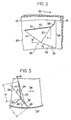
- Figure 2 is a partial perspective view showing an engaging flap in the blank of Figure 1;
- Figure 3 is a partial bottom view showing the engaging flap in the blank of Figure 1;
- Figure 4 is a side elevation showing, partly in section, one embodiment of the closure constructed in accordance with this invention;
- Figure 5 is a side elevation showing, partly in section, the closure of Figure 4 as it is mounted on the mouth-neck portion of a container;
- The invention will be described in greater detail with reference to the accompanying drawings.
- Figure 1 shows a closure blank to be processed into one embodiment of the closure constructed in accordance with this invention. The blank shown generally at 2, which is formed from a suitable plastic material such as polypropylene or polyethylene by injection molding, compression molding, etc., has a circular
top panel wall 4 and acylindrical skirt wall 6 extending downwardly from the peripheral edge of thetop panel wall 4. Anannular protrusion 8 is formed in the upper end portion of the inner surface of theskirt wall 6 so that it projects radially inwardly from the upper end portion. In the lower part of the peripheral surface of theskirt wall 6 is formed astep portion 10 displaced diametrically inwardly. Aportion 12 above thestep portion 10 has a considerable wall thickness, whereas the thickness of aportion 14 below thestep portion 10 is decreased. In the illustrated embodiment, astep portion 16 is formed also on the inner circumferential surface of theskirt wall 6 below thestep portion 10, and theportion 14 has a relativelythick portion 18 above thestep portion 16 and a relativelythin portion 20 below thestep portion 16. As will be clear from a description given hereinbelow, the thickness t1 of theportion 20 is sufficiently small, and preferably 0.05 to 0.75 mm, especially 0.20 to 0.50 mm. The thickness t2 of the relativelythick portion 18 is conveniently 0.50 to 1.10 mm, especially 0.75 to 0.85 mm. If desired, the thickness t2 of theportion 18 can be made sufficiently small as in the portion 20 (therefore, thestep portion 16 does not exist). A raised and depressed orknurled portion 22 is formed on the peripheral surface of theportion 12 of theskirt wall 6 in order to prevent slippage of a finger which engages it. Aninternal thread 24 is formed on the inner circumferential surface of'theportion 12 of theskirt wall 6. A plurality of circumferentially spacedengaging flaps 26 are formed on the inner circumferential surface of theportion 14 of theskirt wall 6. Each of theengaging flaps 26 is projected radially inwardly from itsbase edge 28 connected to the inner circumferential surface of theportion 14. As will be clear from a description given hereinbelow, it is important that at least a greater portion of thebase edge 28 of each of theengaging flaps 26 be positioned in the relativelythin portion 20 below thestep portion 16 in theportion 14. In the illustrated embodiment, the upper end of thebase edge 28 of each of theengaging flaps 26 is positioned in alignment with thestep portion 16. Hence, theentire base edge 28 of each of theengaging flaps 26 is positioned in the relativelythin portion 20 betow thestep portion 16. - According to this invention, the following improvement is made in the
engaging flaps 26. With reference to Figures 2 and 3, each of theengaging flaps 26 is bent along abending line 30 and defined by afirst portion 32 extending from thebase edge 28 to thebending line 30 and asecond portion 34 extending from thebending line 30 to its free end. Thebase edge 28 extends substantially parallel, and therefore substantially vertically, to the central axis 36 (Figure 1) of the blank 2. If desired, however, thebase edge 28 may be inclined in a suitable direction with respect to the central axis 36 (Figure 1) of the blank 2; namely it may be inclined downwardly at a suitable angle to the closing direction of the closure for mounting the closure on the mouth-neck portion of the container (the clockwise direction as viewed from above in Figure 1, the direction shown byarrow 36 in Figures 2 and 3) or in an opposite direction. Preferably, thefirst portion 32 is inclined in a direction opposite to the aforesaid closing direction and extends radially from thebase edge 28. The angle a of inclination of thefirst portion 32 to the inner surface of theportion 20 is preferably 5° £ α ≤ 85°, more preferably 20° ≤ a % 80°, especially preferably 30° ≤ a % 70°. It is important that thesecond portion 34 extending radially inwardly from the bendingline 30 should extend inclinedly with respect to thefirst portion 32 in the aforesaid closing direction. The angle β of inclination of thesecond portion 34 to thefirst portion 32 is preferably 0° < β ≤ 90°, more preferably 0° < β ≤ 70°, especially preferably 5° < β ≤ 45°. The bendingline 30 may extend substantially parallel, and therefore substantially vertically to the central axis 36 (Figure 1) of the blank 2, or may be inclined downwardly approaching the inner surface of theportion 20. Preferably, it is inclined downwardly in a direction away from the inner surface of theportion 20. The angle of inclination of thebending line 30 to the downward direction away from the inner surface of theportion 20 is preferably 5° ≤ y % 80°, more preferably 10° ≤y % 60°, especially preferably 20° ≤y % 50°. - As shown in Figures 1 and 2, the
upper edge 38 of thefirst portion 32 conveniently extends downwardly inclinedly in a radially inward direction forming a gentle curve, and theupper edge 40 of thesecond portion 34 extends nearly horizontally. On the other hand, it is convenient that thelower edge 42 of thefirst portion 32 and thelower edge 44 of thesecond portion 34 extend upwardly inclinedly in a radially inward direction. Generally, the angle 52 of inclination of thelower edge 44 of thesecond portion 34 is slightly larger than theangle 61 of inclination of thelower edge 42 of thefirst portion 32. Conveniently, theangle 61 of inclination is 10° ≤ δ1 ≤ 30°, and theinclination angle 62 is 20° % δ2 ≤ 50°. - With reference to Figure 4 together with Figure 1, to produce the container closure of this invention, a circumferential
breakable line 46 is formed in the blank 2. As shown in Figure 4, the circumferentialbreakable line 46 is disposed immediately below thestep portion 10, and therefore, theportion 12 having a considerable thickness located above thestep portion 10 constitutes a main portion of theskirt wall 6; and theportion 14 having a decreased thickness below thestep portion 10 composed of the relativelythick portion 18 and the relativethin portion 20 constitutes a pilfer-proof bottom portion. The circumferentialbreakable line 46 itself is comprised of a plurality of circumferentially spaced and circumferentially extendingslits 50 and a plurality of bridgingportions 52 located among theslits 50. Theportion 14, i.e. the pilfer-proof bottom portion 14, is connected to theportion 12, i.e. themain portion 12 of theskirt wall 6, via the bridgingportions 52. - The formation of the
sealing liner 58 can be effected by a molding method known per se. Instead of forming thesealing liner 58 separately, a sealing protrusion of a suitable shape may be integrally formed on the inner surface of thetop panel wall 4 of the blank 2. - The
finished closure 60 so formed is applied to a container having a mouth-neck portion 62 of the form indicated in Figure 5. On the cylindrical peripheral surface of the mouth-neck portion 62, anexternal thread 64 and a holdingjaw portion 66 beneath it are formed. - In closing the mouth-
neck portion 62 with theclosure 60, theclosure 60 is put over the mouth-neck portion 62 and turned in a closing direction, that is, in the clockwise direction as viewed from above in Figure 5. As a result, theinternal thread 24 formed in theclosure 60 is engaged with theexternal thread 64 formed in the mouth-neck portion 62, and theclosure 60 is moved axially downwardly. Each of the engagingflaps 26 formed in theclosure 60 thus goes past theexternal thread 64 formed on the mouth-neck portion 62 and further passes over the holdingjaw portion 66. During passage over the holdingjaw portion 66, each of the engaging flaps 26 undergoes interference by the holdingjaw portion 66 and is elastically bent radially outwardly. When theinternal thread 24 of theclosure 60 is fully engaged with theexternal thread 64, each of the engagingflaps 26 completely goes past the holdingjaw portion 66 and is released from interference by the holdingjaw portion 66. As a result, the engagingflaps 26 are elastically returned to their original state. - It will be clearly understood from Example and Comparative Example given hereinbelow that the required downwardly rotating torque which must be exerted on the
closure 60engaging flaps 26 over the holdingjaw portion 66 is nearly equal to that in a conventional container closure in which thesecond portion 34 of each engagingflap 26 is not bent with thefirst portion 32 but extends in a straight line with thefirst portion 32 as shown by a two-dot chain line in Figure 3, and is therefore sufficiently low. - When the engaging
flaps 26 fully return to their original state, they engage the undersurface of the holdingjaw portion 66 as clearly shown in Figure 5. When theinternal thread 24 of theclosure 60 is in full engagement with theexternal thread 64 on the mouth-neck portion 62, thesealing liner 58 is in intimate contact with the end surface portion of the mouth-neck portion 62, and thus seals up the mouth-neck portion 62. - To open the mouth-
neck portion 62, theclosure 60 is turned in the opening direction, i.e. counterclockwise as viewed from above in Figure 5. Thus, theinternal thread 24 of theclosure 60 moves along theexternal thread 64 of the mouth-neck portion 62, and therefore, theclosure 60 moves axially upwardly as it is turned. The pilfer-proof bottom portion 14, however, cannot move axially upwardly since the engagingflaps 26 formed on its inner surface and engaged with the undersurface of the holdingjaw portion 66 of the mouth-neck portion 62. Consequently, a considerable stress is generated on the circumferentialbreakable line 46, and more specifically on itsbridging portions 52. The bridgingportions 52 of the circumferentialbreakable line 46 are therefore broken. As will be clearly understood from the description of the following Example and Comparative Example, the engagingflaps 26 engage the undersurface of the holdingjaw portion 66 more strongly in theclosure 60 improved in accordance with this invention than in the conventional closure in which thesecond portion 34 of each engagingflap 26 is not bent with respect to thefirst portion 32 but extends in a straight line with thefirst portion 32 as shown by the two-dot chain line in Figure 3. In other words, the required upwardly rotating torque which must be exterted on theclosure 60 of this invention when the engagingflaps 26 are passed in the elastically bent state over the holdingjaw portion 66 in the axially upward direction is made considerably higher than that on the conventional closure. Hence, theclosure 60 is surely prevented from being removed from the mouth-neck portion 62 without the desired breakage of thebreakable line 46, and the pilfer-proof characteristics of theclosure 60 can be retained. - Ten blanks having substantially the same form as the blank 2 shown in Figures 1 to 3 were molded from polypropylene having a melt index of 2.0 and a density of 0.90. Each blank has an internal thread inside diameter d of 25.4 mm, an upper portion outside diameter D of 30.0 mm and a total height H of 19.0 mm. Each of the engaging
flaps 26 formed on the inner surface of theportion 20 had the following specification. - Thickness W: 0.35 mm
- Length 11 of the
lower edge 42 - of the first portion 32:1.9 mm
- Length 12 of the
lower edge 44 - of the second portion 34:2,0 m
- Inclination angle a: 50°
- Inclination angle (3: 10°
- Inclination angle y: 30°
- Inclination angle 51: 20°
- Inclination angle 62: 45°
- The
upper edge 38 of thefirst portion 32 was of an arcuate shape having a radius of 0.5 mm, and theupper edge 40 of thesecond portion 34 was substantially horizontal. - Each of the blanks was mounted on the mouth-
neck portion 62 of a glass container having the form shown in Figure 6 and a nominal diameter of 28 mm, and the required downwardly rotating torque was measured. - Thereafter, the blank was forcedly removed from the mouth-
neck portion 62, and the required upwardly rotating torque was measured. The results are shown in Table 1 below. - For comparison, ten blanks same as in Example were molded except that each of the engaging
flaps 26 formed on the inner surface of theportion 20 had the form shown by the two-dot chain line in Figure 3 (namely, thesecond portion 34 was not bent with respect to thefirst portion 32 but extended in a straight line with the first portion 32). - In the same way as in Example, the required downwardly rotating torque and the required upwardly rotating torque were measured. The results are shown in Table 1.

Claims (21)
Applications Claiming Priority (6)
| Application Number | Priority Date | Filing Date | Title |
|---|---|---|---|
| JP5756/84 | 1984-01-18 | ||
| JP59005756A JPS60158048A (en) | 1984-01-18 | 1984-01-18 | Vessel cover made of synthetic resin having pilfer-proof characteristic |
| JP138904/84 | 1984-07-06 | ||
| JP59138904A JPS6121355A (en) | 1984-07-06 | 1984-07-06 | Vessel cover made of synthetic resin having pilfer-proof characteristic |
| JP224126/84 | 1984-10-26 | ||
| JP59224126A JPS61104959A (en) | 1984-10-26 | 1984-10-26 | Vessel cover made of synthetic resin having pilfer-proof characteristic |
Related Child Applications (2)
| Application Number | Title | Priority Date | Filing Date |
|---|---|---|---|
| EP88116832.2 Division-Into | 1985-01-17 | ||
| EP88116832A Division EP0308995A3 (en) | 1984-01-18 | 1985-01-17 | Pilfer-proof plastic closure for containers |
Publications (3)
| Publication Number | Publication Date |
|---|---|
| EP0149496A2 EP0149496A2 (en) | 1985-07-24 |
| EP0149496A3 EP0149496A3 (en) | 1987-05-27 |
| EP0149496B1 true EP0149496B1 (en) | 1990-01-03 |
Family
ID=27276882
Family Applications (2)
| Application Number | Title | Priority Date | Filing Date |
|---|---|---|---|
| EP85100467A Expired - Lifetime EP0149496B1 (en) | 1984-01-18 | 1985-01-17 | Pilfer-proof plastic closure for containers |
| EP88116832A Withdrawn EP0308995A3 (en) | 1984-01-18 | 1985-01-17 | Pilfer-proof plastic closure for containers |
Family Applications After (1)
| Application Number | Title | Priority Date | Filing Date |
|---|---|---|---|
| EP88116832A Withdrawn EP0308995A3 (en) | 1984-01-18 | 1985-01-17 | Pilfer-proof plastic closure for containers |
Country Status (3)
| Country | Link |
|---|---|
| EP (2) | EP0149496B1 (en) |
| KR (1) | KR890002821B1 (en) |
| DE (1) | DE3575115D1 (en) |
Cited By (2)
| Publication number | Priority date | Publication date | Assignee | Title |
|---|---|---|---|---|
| DE4121618A1 (en) * | 1991-06-29 | 1993-01-14 | Alcoa Gmbh Verpackwerke | Plastic bottle cap with reliable seal |
| US7077278B2 (en) | 2001-06-18 | 2006-07-18 | Bericap Holding Gmbh | Screw cap comprising a tamper-evident band |
Families Citing this family (12)
| Publication number | Priority date | Publication date | Assignee | Title |
|---|---|---|---|---|
| IT1191796B (en) * | 1986-05-30 | 1988-03-23 | Guala Angelo Spa | WARRANTY CLOSURE, FOR BOTTLES OF SPIRITS AND SIMILAR |
| EP0254673B1 (en) * | 1986-07-11 | 1990-04-18 | Interplastic AG | Container closure provided with a tamper indicating band |
| GB8817365D0 (en) * | 1988-07-21 | 1988-08-24 | Metal Closures Ltd | Container closure |
| FR2674823B1 (en) * | 1991-04-02 | 1993-07-16 | Astra Plastique | SCREW CAP WITH INVIOLABILITY RING. |
| DK168887B1 (en) * | 1991-09-20 | 1994-07-04 | Dbi Plastics A S | Protective cap for container discharge valves, in particular sticker valves on draft beer holders |
| US5413235A (en) * | 1994-09-28 | 1995-05-09 | Decelles; Gilles | Tamper-evident closure |
| DE102005025581A1 (en) * | 2005-06-01 | 2006-12-07 | Bericap Gmbh & Co. Kg | Cap with integrated guarantee strip and method and device for its manufacture |
| USD747201S1 (en) | 2013-09-18 | 2016-01-12 | Bericap | Closure |
| FR3015442B1 (en) | 2013-12-24 | 2016-02-05 | Bericap | ARTICULATED CLAMPING DEVICE WITH FIRST OPENING INDICATOR |
| USD833278S1 (en) | 2014-09-03 | 2018-11-13 | Bericap | Closure for a container |
| AU2024251131A1 (en) | 2023-04-05 | 2025-09-25 | Husky Injection Molding Systems Ltd. | Closures with tamper evidence |
| USD1116829S1 (en) | 2023-06-13 | 2026-03-10 | Husky Injection Molding Systems Ltd. | Bottle cap |
Family Cites Families (6)
| Publication number | Priority date | Publication date | Assignee | Title |
|---|---|---|---|---|
| DE2529306A1 (en) * | 1975-07-01 | 1977-02-10 | Obrist Ag Albert | METHOD AND DEVICE FOR THE PRODUCTION OF A WARRANTY SEAL |
| FR2457813A1 (en) * | 1979-05-31 | 1980-12-26 | Grussen Jean | Screw cap bottle closure moulded with integral security lip - for containing carbonated drinks |
| JPS5832105B2 (en) * | 1979-11-10 | 1983-07-11 | 日本クラウンコルク株式会社 | Synthetic resin container lid with pill-proof properties |
| FR2499519A1 (en) * | 1981-02-11 | 1982-08-13 | Grussen Jean | SCREW CAPSULE WITH INVIOLABILITY RING |
| US4418828A (en) * | 1981-07-24 | 1983-12-06 | H-C Industries, Inc. | Plastic closure with mechanical pilfer band |
| AU560751B2 (en) * | 1981-07-24 | 1987-04-16 | H-C Industries Inc. | Plastic bottle closure |
-
1985
- 1985-01-17 EP EP85100467A patent/EP0149496B1/en not_active Expired - Lifetime
- 1985-01-17 KR KR1019850000252A patent/KR890002821B1/en not_active Expired
- 1985-01-17 DE DE8585100467T patent/DE3575115D1/en not_active Expired - Lifetime
- 1985-01-17 EP EP88116832A patent/EP0308995A3/en not_active Withdrawn
Cited By (2)
| Publication number | Priority date | Publication date | Assignee | Title |
|---|---|---|---|---|
| DE4121618A1 (en) * | 1991-06-29 | 1993-01-14 | Alcoa Gmbh Verpackwerke | Plastic bottle cap with reliable seal |
| US7077278B2 (en) | 2001-06-18 | 2006-07-18 | Bericap Holding Gmbh | Screw cap comprising a tamper-evident band |
Also Published As
| Publication number | Publication date |
|---|---|
| EP0149496A3 (en) | 1987-05-27 |
| DE3575115D1 (en) | 1990-02-08 |
| EP0149496A2 (en) | 1985-07-24 |
| KR850005356A (en) | 1985-08-24 |
| KR890002821B1 (en) | 1989-08-04 |
| EP0308995A3 (en) | 1989-04-05 |
| EP0308995A2 (en) | 1989-03-29 |
Similar Documents
| Publication | Publication Date | Title |
|---|---|---|
| US4565295A (en) | Plastic container closure having pilferproof characteristics | |
| US4588100A (en) | Pilfer-proof plastic closure for containers | |
| US4809858A (en) | Composite closure cap with removal torque control | |
| EP0149496A2 (en) | Pilfer-proof plastic closure for containers | |
| US4723685A (en) | Lined closure made by the unscrewing process | |
| US5542556A (en) | Plastic closure with structural thread formation | |
| US4369889A (en) | Tamperproof closure | |
| EP0119055A2 (en) | Improvements relating to closures | |
| EP0381118B1 (en) | Tamper-indicating plastic closure | |
| US6068151A (en) | Tamper-indicating plastic closure having pilfer band | |
| US5957315A (en) | Plastic container closure with tamper evident properties | |
| US4799603A (en) | Container and plug closure means | |
| US4668458A (en) | Method of forming a carbonated beverage package | |
| JPH0440268B2 (en) | ||
| US4520939A (en) | Pilfer-proof plastic closure for containers | |
| EP0913334A1 (en) | Synthetic resin container lid having tamper evident characteristics | |
| EP0067650A1 (en) | Tamper-indicating closure | |
| JP3306733B2 (en) | Synthetic resin container lid with tamper-evident properties | |
| JPH0620904B2 (en) | Synthetic resin container lid having pilfer-proof characteristics | |
| FI83616B (en) | Pilfer-proof plastics seal for receptacle | |
| JPH0346380B2 (en) | ||
| FI83617C (en) | Pilferproof closure of plastic for containers | |
| WO2001026989A1 (en) | Closure cap made of plastics material | |
| JPS61104959A (en) | Vessel cover made of synthetic resin having pilfer-proof characteristic | |
| JP3303121B2 (en) | Method for producing container lid made of synthetic resin having tamper-evident properties |
Legal Events
| Date | Code | Title | Description |
|---|---|---|---|
| PUAI | Public reference made under article 153(3) epc to a published international application that has entered the european phase |
Free format text: ORIGINAL CODE: 0009012 |
|
| AK | Designated contracting states |
Designated state(s): DE FR GB IT NL SE |
|
| PUAL | Search report despatched |
Free format text: ORIGINAL CODE: 0009013 |
|
| AK | Designated contracting states |
Kind code of ref document: A3 Designated state(s): DE FR GB IT NL SE |
|
| 17P | Request for examination filed |
Effective date: 19870611 |
|
| 17Q | First examination report despatched |
Effective date: 19880428 |
|
| GRAA | (expected) grant |
Free format text: ORIGINAL CODE: 0009210 |
|
| AK | Designated contracting states |
Kind code of ref document: B1 Designated state(s): DE FR GB IT NL SE |
|
| XX | Miscellaneous (additional remarks) |
Free format text: TEILANMELDUNG 88116832.2 EINGEREICHT AM 17/01/85. |
|
| ITF | It: translation for a ep patent filed | ||
| ET | Fr: translation filed | ||
| REF | Corresponds to: |
Ref document number: 3575115 Country of ref document: DE Date of ref document: 19900208 |
|
| PLBE | No opposition filed within time limit |
Free format text: ORIGINAL CODE: 0009261 |
|
| STAA | Information on the status of an ep patent application or granted ep patent |
Free format text: STATUS: NO OPPOSITION FILED WITHIN TIME LIMIT |
|
| 26N | No opposition filed | ||
| ITTA | It: last paid annual fee | ||
| PGFP | Annual fee paid to national office [announced via postgrant information from national office to epo] |
Ref country code: SE Payment date: 19931130 Year of fee payment: 10 |
|
| PGFP | Annual fee paid to national office [announced via postgrant information from national office to epo] |
Ref country code: FR Payment date: 19931213 Year of fee payment: 10 |
|
| PGFP | Annual fee paid to national office [announced via postgrant information from national office to epo] |
Ref country code: GB Payment date: 19940107 Year of fee payment: 10 |
|
| PGFP | Annual fee paid to national office [announced via postgrant information from national office to epo] |
Ref country code: NL Payment date: 19940131 Year of fee payment: 10 |
|
| PGFP | Annual fee paid to national office [announced via postgrant information from national office to epo] |
Ref country code: DE Payment date: 19940330 Year of fee payment: 10 |
|
| PG25 | Lapsed in a contracting state [announced via postgrant information from national office to epo] |
Ref country code: GB Effective date: 19950117 |
|
| PG25 | Lapsed in a contracting state [announced via postgrant information from national office to epo] |
Ref country code: SE Effective date: 19950118 |
|
| EAL | Se: european patent in force in sweden |
Ref document number: 85100467.1 |
|
| PG25 | Lapsed in a contracting state [announced via postgrant information from national office to epo] |
Ref country code: NL Effective date: 19950801 |
|
| GBPC | Gb: european patent ceased through non-payment of renewal fee |
Effective date: 19950117 |
|
| PG25 | Lapsed in a contracting state [announced via postgrant information from national office to epo] |
Ref country code: FR Effective date: 19950929 |
|
| NLV4 | Nl: lapsed or anulled due to non-payment of the annual fee |
Effective date: 19950801 |
|
| PG25 | Lapsed in a contracting state [announced via postgrant information from national office to epo] |
Ref country code: DE Effective date: 19951003 |
|
| EUG | Se: european patent has lapsed |
Ref document number: 85100467.1 |
|
| REG | Reference to a national code |
Ref country code: FR Ref legal event code: ST |