EP0148923B1 - A high speed evacuation chamber packaging machine and method - Google Patents
A high speed evacuation chamber packaging machine and method Download PDFInfo
- Publication number
- EP0148923B1 EP0148923B1 EP84902754A EP84902754A EP0148923B1 EP 0148923 B1 EP0148923 B1 EP 0148923B1 EP 84902754 A EP84902754 A EP 84902754A EP 84902754 A EP84902754 A EP 84902754A EP 0148923 B1 EP0148923 B1 EP 0148923B1
- Authority
- EP
- European Patent Office
- Prior art keywords
- bag
- hood
- nozzle
- platen
- vacuum
- Prior art date
- Legal status (The legal status is an assumption and is not a legal conclusion. Google has not performed a legal analysis and makes no representation as to the accuracy of the status listed.)
- Expired
Links
Images







Classifications
-
- B—PERFORMING OPERATIONS; TRANSPORTING
- B65—CONVEYING; PACKING; STORING; HANDLING THIN OR FILAMENTARY MATERIAL
- B65B—MACHINES, APPARATUS OR DEVICES FOR, OR METHODS OF, PACKAGING ARTICLES OR MATERIALS; UNPACKING
- B65B31/00—Packaging articles or materials under special atmospheric or gaseous conditions; Adding propellants to aerosol containers
- B65B31/02—Filling, closing, or filling and closing, containers or wrappers in chambers maintained under vacuum or superatmospheric pressure or containing a special atmosphere, e.g. of inert gas
- B65B31/022—Filling, closing, or filling and closing, containers or wrappers in chambers maintained under vacuum or superatmospheric pressure or containing a special atmosphere, e.g. of inert gas the chambers moving in an endless path
Definitions
- a high speed evacuation chamber packaging machine incorporating various features of the present invention is generally indicated at 10 in Figure 1.
- This machine is designed for packaging and sealing flexible receptacles or usually heat shrinkable polymeric bags containing a product (such as meat) desired to be packaged in a vacuum.
- the machine 10 is designed for being used as an in-line machine which is compact and readily integrated into existing packaging procedures without costly modifications which might otherwise be required to expedite product flow. While the machine is designed for in-line operation, it should be recognized that its use is not limited to such operation and that the principles and features of the invention could be readily incorporated in various machine embodiments.
- the machine 10 illustrated in Figure 1 includes a plurality of rotating stations to be defined in greater detail hereinafter, such stations could be arranged in other configurations, such as being carried by a conveyer or the like.
- FIG. 13 One suitable vacuum control valve or vacuum valve is illustrated generally at 124 in Figure 13.
- This vacuum control valve includes a housing 126 having a plurality of ports therein.
- the housing receives a rotor 128 which can be advanced longitudinally within the housing by the injection of air or another suitable fluid through the port 7.
- the longitudinal position of the rotor 128 is shifted toward the opposite end portion of the housing 126.
- the introduction of air into port 8 at the opposite end of the housing will shift the rotor toward the port 7.
- the opposite ends of the flattened rotor serve as the head portion of a piston for longitudinal movement of the rotor.
- this piston 130 includes a substantially cylindrical head slideably received within the cylinder portion 132 of the housing 126. Upon the introduction of a fluid such as air through the port 6 this piston 130 is moved downwardly to the position illustrated in Figure 13.
- the piston 134 is drivingly connected through the rotor arm 136 through a pivotally mounted fork 138 which is carried by the wall of the housing.
- the piston arm 134 and the fork 138 are joined by the rod 140 which is received within the illustrated slot defined in the fork 138.
- the forward most end portion of the rotor arm 136 is received within the registering slots 142 of the fork 138.
- control system selectively controls various fail safe features which assist in preventing damage to the machine during its operation. More specifically, the switches labeled S1-S10 are mechanically actuated and serve to control various of the valves labeled V1-V10 for selectively supplying or eliminating the supply of pneumatic pressure to the various cylinders and the vacuum control valve 124.
- the station rotates to the 8:00 position and the hood is raised by tripping the switch S3. Also in response to tripping switch S3, the hood is vented by the positioning of the vacuum control valve in the position illustrated in Figure 15C. The primary vacuum is continually applied to the nozzle.
Landscapes
- Chemical & Material Sciences (AREA)
- Dispersion Chemistry (AREA)
- Engineering & Computer Science (AREA)
- Mechanical Engineering (AREA)
- Vacuum Packaging (AREA)
- Containers And Plastic Fillers For Packaging (AREA)
- Auxiliary Devices For And Details Of Packaging Control (AREA)
Abstract
Description
- The invention relates to an evacuation chamber packaging machine according to the preamble of
claim 1. - Such a machine is known from DE-A-2 247 452. This machine includes means for evacuating the volume within the bag in which a product is to be stored. This machine further includes means for evacuating an external evacuating chamber surrounding the bag.
- Another prior art device is illustrated in US-A-3795085. This device includes a rotatable assembly having a circular table portion and a plurality of radially oriented evacuation nozzles and clamps for each nozzle for sealing the bag neck on the nozzle during the evacuation operations. Other known prior art devices generally relating to the field of the present invention are described in the following US patent numbers: 4,189,897; 4,049,020; 3,648,430, and the prior art documents references in such United States patents.
- It is an object of the present invention to provide a high speed evacuation chamber packaging machine which produces a bagged product having minimal air pockets and which can be operated at a high speed.
- This object is solved by the features of the characterizing clause of
claim 1. This machine can easily control the pressure differential inside and outside of the bag during the evacuation operation such that air pockets normally generated within the bag are minimized. Furthermore, the machine can be economically manufactured and readily cleaned. The machine of the present invention is designed so that it can be operated in an automatic mode which creates a differential pressure within and without the bag or it can be operated in a mode such a negative pressure is generated within the bag only. Thus the machine can be used to package various sized products and even products which cannot be contained within the hoods. - The above-mentioned features of the present invention will be more clearly understood through consideration of the following description together with the accompanying drawings in which:
- Fig. 1 illustrates a high speed evacuation chamber packaging machine incorporating various features of the present invention. This figure illustrates a plan view of the machine, and it should be understood that the number of stations and the geometric configuration of the machine itself can vary.
- Figures 2A-C illustrate a machine station at various positions during the machine operation.
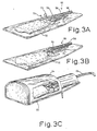
- Figures 3A-C further depict a machine station and particularly the motion associated with the clamps which seal the bag about the nozzle during the evacuation operation.
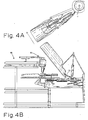
- Figure 4A illustrates a plan view of a single station together with the motion of its travel.
- Figure 4B diagrammatically illustrates a side elevation view of the machine during the sealing and clipping operation.
- Figure 5 illustrates the machine operation during unloading.
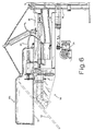
- Figure 6 illustrates a side elevation view of a station together with the means for rotatably driving the wheel member which carries the various annularly spaced stations.
- Figure 7 illustrates a plan view of adjacent stations and the wells within which portions of the clamps and the clamp drives are carried by the platen to the station. More specifically, the left hand station shows the platen and nozzle arrangement, and the other station illustrates features below the platen surface.
- Figure 8 illustrates a cross-sectional view of the hub and portions of the wheel.
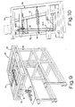
- Figures 9 and 10 illustrate a means for carrying the clipping and trimming device along a path substantially identical to the path of travel of the bag neck as it is carried by a station.
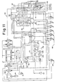
- Figure 11 illustrates a pneumatic schematic of the control system.
- Figure 12 is a diagrammatic illustration of a vacuum control valve illustrating the various vacuum and vent connections made with the hood and nozzle.
- Figure 13 illustrates a sectional perspective view of an exemplary vacuum control valve which is connected into the pneumatic system as shown in Figure 14 for selectively applying the desired . vacuum and/or vent to the hood and nozzle.
- Figures 15A-D illustrate the various positions of the vacuum control valve depicted in Figures 13 and 14.
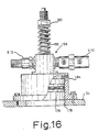
- Figure 16 is an elevation view of a vacuum activator with a portion of the housing broken away for purposes of illustration.
- Referring now to the drawings, a high speed evacuation chamber packaging machine incorporating various features of the present invention is generally indicated at 10 in Figure 1. This machine is designed for packaging and sealing flexible receptacles or usually heat shrinkable polymeric bags containing a product (such as meat) desired to be packaged in a vacuum. The
machine 10 is designed for being used as an in-line machine which is compact and readily integrated into existing packaging procedures without costly modifications which might otherwise be required to expedite product flow. While the machine is designed for in-line operation, it should be recognized that its use is not limited to such operation and that the principles and features of the invention could be readily incorporated in various machine embodiments. For example, while themachine 10 illustrated in Figure 1 includes a plurality of rotating stations to be defined in greater detail hereinafter, such stations could be arranged in other configurations, such as being carried by a conveyer or the like. - The
machine 10 includes aframe 12 which is mounted on a suitable supporting surface such as the floor of a building. Thisframe 12 includes astationary hub 14 as illustrated in Figure 1 and in Figure 8. Thishub 14 defines alower pedestal 21 which includes anannular shoulder 23. The lower portion of thepedestal 21 is mounted or positioned on the floor as is illustrated in the cross-sectional view in Figure 8. This hub is substantially hollow and incorporates conduits 20 and 22 which serve to provide fluid communication between thepneumatic air supply 122 and theprimary vacuum source 15, respectively, as illustrated diagrammatically in Figure 8. Theupper end portion 25 of the conduit 20 connects thepneumatic air supply 122 through a conventional union (not shown) to each of thestations 18 as will be described in greater detail hereinafter. Thus, the air supplied through the conduit 20 feeds the stations for accomplishing the various pneumatic operations. - The
primary vacuum source 15 and thesecondary vacuum source 17 are of conventional design and will incorporate a suitable motor which will generate the desired negative pressure for accomplishing the evacuation of the chamber and of the bag to a desired level. Moreover, a conventional control system (not shown) will normally be provided to allow adjustment of the vacuum level of theprimary vacuum source 15 and thesecondary vacuum source 17. For example, in a preferred embodiment, the secondary vacuum source which is applied to the hood can be adjusted between approximately 12 inches Hg (0.04 MPa) and 26 inches Hg (0.09 MPa). Theprimary vacuum source 15, will normally be adjusted to a leyel greater than the level of the secondary vacuum source during the machine operation. - As illustrated in Figure 8, an alternate or secondary vacuum source 17' is provided as a back-up. Each of the secondary vacuum sources are connected in fluid communication with the toroidial shaped chamber 27 in the hub. The secondary vacuum source is connected through the annularly spaced
ports 29 and thevacuum valve 124 with the hood to be described in greater detail hereinafter. Similarly, the primary vacuum source is connected through conduit 22, hub chamber 33 and ports 31 to the nozzle and vacuum valve. - This
hub 14 carrieswheel member 16 which is rotatably driven about the hub by conventional drive means such as the motor 20 illustrated in Figure 6. It will be noted that this motor 20 is connected to thewheel member 16 by a conventional drive method such as a timing belt, gears, etc. A belt drive is shown in Figure 6.Wheel member 16 is driven at a preselected speed which is coordinated with the loadings, off loading and other machine operations. The hub is seated on a bronze bearing, in the preferred embodiment, generally indicated at 35. This bearing is supported by thehub shoulder 23 and allows thewheel member 16 to rotate with respect to the hub andhub pedestal 21. - During rotation, the primary vacuum source is connected to the nozzle of each station through the
vacuum valve 124, to be described in greater detail hereinafter, as is indicated by the air flow arrow 41. It will be seen that this arrow 41 passes through thewheel member port 45, the ports 31 and connects the nozzle with theprimary vacuum source 15. Similarly, the hood is connected to the secondary vacuum source 17 (and optionally 17') through thewheel member port 47 and thehub ports 29 as is indicated by theflow arrow 43. - Each of the
stations 18 is supported by radially extending spokes or arms. Portions of theupper arms 26 and thelower arms 28 are illustrated in Figure 8. Figure 6 further exemplifies thearms typical station 18. - Each of the
stations 18 includes a substantiallyplaner platen 32 which serves to carry the bagged product during the evacuation and sealing operations. In this connection, the platen defines a product zone which faces upwardly and supports the bagged product subsequent to its being loaded on such platen as by an operator. Ahood 34 is operatively associated with each of theplatens 32 and can be moved from an open position as illustrated in Figure 2B for loading and unloading the bagged product to a closed position as illustrated in Figure 2A. Upon closing thehood 34 to its sealed position, achamber 36 is defined between the interior surface of the hood and the upwardly facing platen. Thischamber 36 is hermetically sealed as by providing a rubber seal or gasket along thelower edge 38 of the hood (see Figure 2B). Thehood 34 is moved from its opened to its closed position by the pneumatic cylinder and associated piston generally indicated at 40 in Figure 2. This piston and cylinder are of conventional design and serve to pivot the hood about thepivot point 42 by operation on thearms arm 26 is shown in greater detail in Figure 7. Thesecondary vacuum source 17 is selectively connected to thechamber 36 defined by closing the hood through a vacuum hose or conduit 19 (see Figure 3C). ' - Means are provided at 50 for extending and retracting the
platen 32 to facilitate loading and unloading the bagged product. More specifically, this means 50 includes a first pneumatic cylinder andpiston 52 which is carried by the arm 26 (see Figures 2 and 7). Upon activation of this cylinder, the platen extends from the position illustrated in Figure 2A to the position illustrated in 2B. Thus, activation of thecylinder 52 serves to drive the operatively associated piston arm forward which in turn slides the platen forward to the position as illustrated in Figure 2B to facilitate loading the bagged product onto the platen when the hood is in its raised position. - In order to facilitate unloading the bagged product from the platen, means 58 (see Figures 2 and 7), which comprises a pneumatic cylinder and associated piston, serves to move the
platen 32 to a sloped position as shown in Figure 2C. In this regard, thestation arms guides 60 mounted on each side of the station. These guides operatively receive associated guide rollers orrods 62 which follow the path defined by theguides 60 upon activation of the slopingcylinder 58. Thus, when thecylinder 58 is activated with piston ofcylinder 52 in the extended position, the platen and its frame which carry the guide rollers are moved to the position indicated in Figure 2C. - A nozzle assembly generally indicated at 66 serves to evacuate the interior portion of the bag. This
nozzle assembly 66 is more clearly illustrated in Figures 7 and 3A-C and includes anozzle 56 mounted at a spaced location above the upper surface of theplaten 32. Therearward end portion 68 of the nozzle is connected in fluid communication with a primary vacuum source which serves to evacuate the contents of the bag as illustrated in Figure 3A. A forward end portion of the nozzle indicated at 70 serves to receive the neck portion of the bag which is gathered about this forward end portion of thenozzle 56 during preparation of the bagged product for the evacuation and clipping operation. - In this connection, cooperating clamps 72 are provided, each of which include an indented section, as is illustrated in Figures 3A-C, which gathers and seals the bag about the
forward end 70 of thenozzle 56. Theforward end 70 of the nozzle is provided with an annular groove which received the registering grooves or indented sections of the pivotally mountedclamps 72. Thus, when the clamps are in the closed position as illustrated diagrammatically in Figures 3B and 3C, the neck portion of the bag is hermetically sealed with the forward end portion of the nozzle such that the bag can be evacuated to a desired level. - The
clamps 72 are pneumatically operated from their open position illustrated in Figure 3A to their closed position as illustrated in Figure 3B. Portions of the clamps and the conventional pneumatic drives for the clamps are mounted in thewells 61 of the platen shown in Figure 7. A slopedplate 74 is mounted proximate theforward end portion 70 of thenozzle 56 and supports a switch S9 which is manually actuated by an operator to initiate pneumatic closure of the clamps and movement of the gatheringrods 76 from their opened position illustrated in Figure 3A to their closed position illustrated in 3B. These gatheringrods 76 gather the neck portion of the bag and are pneumatically operated by means 78 carried in thewells 61 of the platen 32 (see Figures 2A and 7) which simultaneously close the gathering rods and the clamps. - A pneumatically actuated probe 80 (see Figures 2A and 7) is slideably received within the
nozzle 56. This probe serves to position or stand-off the product contained in the bag at a location remote from theclamps 72 and the gatheringrods 76, and is provided with a plurality of annularly spaced grooves which serve to define paths for the travel of air drawn from the bag during the evacuating operation. Thus, upon closure of the clamps to hermetically seal the neck of the bag with thenozzle 56, the desired vacuum is applied through theend portion 68 of the nozzle. This vacuum draws air from the bag and through the annularly spaced grooves in the probe which serve to prevent the neck of the bag from forming a seal with a nozzle end probe during evacuation. - After the bag has been evacuated to a desired level, the bag is sealed and trimmed to secure the product at the desired vacuum level and prepare it for the off loading operation. The bag can be sealed by a number of conventional devices or methods; for example, it can be heat sealed, tied, clipped, etc. In the illustrated embodiment, the sealing is accomplished by a clipping and trimming device generally indicated at 84 and is shown in Figure 4B. This device is of conventional design and examples of suitable devices are illustrated by U.S. Patent Nos. 3,583,056, 3,576,088, and 3,266,138.
- It has been found, however, that the speed of the machine operations and the effectiveness of the seal can be enhanced by moving the clipping and trimming device along the path of the neck portion of the bag while such clipping and trimming operation is accomplished. In this connection, means generally indicated at 86 serve to carry the clipping and trimming
device 84 along an arc, in the preferred embodiment, which is substantially identical to the arc of travel of the neck of the bag which is carried by an operatively associated station, such that the clipping and trimming device and the neck of the bag travel along a substantially identical path while such operations are being performed. More specifically, a frame 88 (see Figures 9 and 10) serves to mount the means for carrying the clipping and trimmingdevice 84 at a preselected location. Thisframe 88 includes anupper portion 90 which pivotally receives acarriage 92 upon which is mounted the clipping and trimmingdevice 84. Thiscarriage 92 is mounted such that the forward portion of the carriage to which is secured the clipping and trimmingdevice 84, selectively travels along an arc substantially identical to the arc of travel of the neck portion of the bag. In this regard, thecarriage 92 is pneumatically driven by the drive means 94 which in the illustrated embodiment comprises a pneumatic cylinder and associated piston which is secured at itsoutboard end portion 96 to across member 98 of thecarriage 92 as illustrated in Figures 9 and 10. The precise path of travel of the forward end portion of thecarriage 92 which carries the clipping and trimming -device 84 is controlled by the cooperating racks 100A and 100B and operatively associated pinions 102A and 102B, respectively. It will be noted that these pinions are interconnected by thechain 104 which engagesgear 106 mounted on theframe 88. Thus, when the drive means orpneumatic cylinder 94 is activated, a piston pushes the carriage end portion to which is secured the device 82 in the direction of travel of the neck portion of the bag. The activation of the drive means 94 is coordinated with the speed of travel of the bag, and the path of the carriage means as defined by the carriage path control means comprising the illustrated racks, pinions, chain, and gear such that the clipping and trimming device travels along an arc substantially identical to the travel of the neck portion of the bag. - Subsequent to completion of the clipping and trimming operations, the drive means 94 is retracted to position the clipping and trimming device at a location for commencing the next clipping and trimming operation on a bag carried by the trailing adjacent station.
- Subsequent to the clipping and trimming operation, the stations which travel in a clockwise direction as seen in Figure 1, advance to the unloading or off-loading position, generally indicated at 110 in Figure 1 and illustrated in greater detail in Figure 5. At the unloading position, the platen is sloped as illustrated in Figure 5, so that the bagged product slides along the upper surface of the platen onto a
conveyer 112 of conventional design. As shown in Figure 1, this conveyer carries the bagged product in the direction of thearrow 114 or as desired, the conveyer can be directed such that the bagged product is carried away from themachine 10 by an alternate conveyer position as illustrated at 116. It will, of course, be recognized that the conveyer is optional and that an operator standing proximate the location indicated at the 110 can unload the bagged product manually if necessary or desired. Subsequent to the unloading operation, aplaten 32 is retracted to the position illustrated in Figure 2B and the loading operation commences. - The hood is selectively connected with a
secondary vacuum source 17 to evacuate thechamber 36 and cause the bag to balloon prior to the bag being evacuated to a lesser pressure by the primary vacuum source. It has been found that this process minimizes the development of air pockets within the bag next to the product. In the preferred embodiment, the sequencing of the vacuum application to the hood and nozzle is carefully controlled with avacuum valve 124. The various modes of operation of this vacuum valve are shown diagrammatically in Figure 12. As shown, thevacuum valve 124 selectively applies thevent 152 or thesecondary vacuum 17 tohood 34. Also, as shown, theprimary vacuum 15 is selectively applied to the nozzle. - One suitable vacuum control valve or vacuum valve is illustrated generally at 124 in Figure 13. This vacuum control valve includes a
housing 126 having a plurality of ports therein. The housing receives arotor 128 which can be advanced longitudinally within the housing by the injection of air or another suitable fluid through theport 7. In this connection, the longitudinal position of therotor 128 is shifted toward the opposite end portion of thehousing 126. The introduction of air intoport 8 at the opposite end of the housing will shift the rotor toward theport 7. Thus, the opposite ends of the flattened rotor serve as the head portion of a piston for longitudinal movement of the rotor. - Rotation of the rotor for proper alignment or connection of the nozzle and hood with the vacuum source and vent is accomplished by the
piston 130. More specifically, thispiston 130 includes a substantially cylindrical head slideably received within thecylinder portion 132 of thehousing 126. Upon the introduction of a fluid such as air through theport 6 thispiston 130 is moved downwardly to the position illustrated in Figure 13. As shown, thepiston 134 is drivingly connected through the rotor arm 136 through a pivotally mountedfork 138 which is carried by the wall of the housing. Thepiston arm 134 and thefork 138 are joined by therod 140 which is received within the illustrated slot defined in thefork 138. The forward most end portion of the rotor arm 136 is received within the registering slots 142 of thefork 138. - In order to shift the
piston 130 to its upper most position, proximate theport 6, a fluid such as air is injected through theport 5 which opens into the area of thecylinder 132 below the piston head. Thus the introduction of a pressurized fluid such as air into such area of the cylinder will raise the piston with respect to its position as shown in Figure 13 and thereby rotate therotor 128 approximately 90 degrees. - The various positions of the
vacuum valve 124 for accomplishing the desired connections with hood and nozzle are illustrated in Figures 15A-15D. More specifically, therotor 128 is flattened for illustrative purposes and the ports of the valve which are connected by the grooves in the rotor are illustrated by shaded lines. As shown in. Figure 15A, therotor groove 146 is L-shaped in geometric configuration and therotor groove 148 as illustrated in Figure 15A is spaced annularly therefrom. - Upon injection of air through the
ports grooves rotor 128 with the ports in the housing is illustrated. Port 150V is connected in fluid communication with thevent 152 diagrammatically illustrated in Figure 14. Theport 150H is connected with thehood 134 through theconduit 19. Thehousing port 150S is connected in fluid communication with the secondary vacuum source 17 (see Figure 14). Thehousing port 150N is connected with thenozzle 56. Thehousing port 150P is connected with the primary vacuum source 15 (see Figure 14). - When air is injected through
ports valve 124, illustrated in Figure 13, the valve is in an off position since neither the hood nor the nozzle are connected by thegrooves - Upon introduction of a pneumatic pressure into the housing through
port 6, the piston is driven downwardly as seen in Figure 13 and the rotor is rotated such that the hood andnozzle port port 7. In this position, the hood is connected with thesecondary vacuum source 17 and the nozzle is sealed or in an off position. - By introducing pneumatic pressure through the
port 8 of the vacuum control housing, illustrated in Figure 13, the hood valve connection illustrated in Figure 15C is established. More specifically, in this position the nozzle is connected through thegroove 148 with theprimary vacuum source 15 and the hood is vented through thegroove 146 to thevent 152. This hood and nozzle connection position is established by injecting air through theport 8 and injecting air through theport 6 to drive the piston downwardly as seen in Figure 13. - The final hood and nozzle vacuum connection established by the vacuum valve is illustrated in Figure 15D. In this configuration, pneumatic pressure has been introduced through
port 5 to drive thepiston 134 in an upwardly direction as seen in Figure 13, thereby rotating therotor 128 approximately 90 degrees and connecting the hood to the vent and sealing the nozzle as illustrated. This is the condition established for safety purposes in response to the vacuum level activator diagrammatically illustrated in Figure 11 at 156 detecting a preselected vacuum condition as may be established upon the bag bursting for example. Thisvacuum level activator 156 will be described in greater detail hereinafter. More specifically, if the bag were to burst within the hood, thisvacuum level activator 156 would cause an automatic introduction of air through theport 5 to shift the nozzle and hood vacuum conditions to the situation illustrated in Figure 15D. - Referring now in greater detail to the pneumatic system and the operational sequence of the preferred embodiment, a schematic diagram of the control system is illustrated generally at 120 in Figure 11. While the embodiment described uses pneumatic switching and valving, it will of course be recognized by those skilled in the art that alternate means of powering and controlling the system can be provided. For example, the operational sequence of the system and the switching of the various pneumatic components could be controlled electronically as with a microprocessor.
- The control system generally indicated at 120, controls the mechanical movements associated with the various stations, and each of the
stations 18 will be connected in the illustrated embodiment to acontrol system 120. More specifically, thepneumatic control system 120 is connected to a pneumatic source illustrated diagrammatically at 122. This source is of conventional design and serves to supply pneumatic pressure through the various conduits of thecontrol system 120 to activate the cylinders for raising and lowering the hood, for extending and retracting the platen and for extending and retracting the probe. Also, thepneumatic supply 122 is selectively connected with thevacuum control valve 124 which controls the connection of the nozzle and the hood with the primary, and secondary vacuum sources, respectively, and with a vent to the ambient atmosphere. Moreover, the control system selectively controls various fail safe features which assist in preventing damage to the machine during its operation. More specifically, the switches labeled S1-S10 are mechanically actuated and serve to control various of the valves labeled V1-V10 for selectively supplying or eliminating the supply of pneumatic pressure to the various cylinders and thevacuum control valve 124. - It will be recognized that suitable seals will be provided in the
vacuum control valve 124 to seal the rotor and its grooves from the housing. Similarly, seals will be provided proximate the ends of the rotor to affect the longitudinal movement. - The
vacuum valve 124 is shifted longitudinally by a pneumatic pressure of approximately 20 p.s.i. (0.14 MPa) in the preferred embodiment to prevent damage to the valve components. In this connection, valve V5 through which the shifting of thecontrol valve 124 is accomplished through thelines 158, connects the reducedpressure supply line 125 to the shiftingports supply line 125 is less than the pressure in the lines connected to thesource 122 which supplies the various cylinders. Valve V4 which supplies axial shifting toports line pressure 122. - The general operation of the machine will now be described in connection with various mechanical movements and in connection with the pneumatic diagram described in Figure 11. Generally, switches S1-S8 and S10 are carried proximate the
lower arms 28 on each station and are activated by traveling over a tripper illustrated diagrammatically at 160 in Figure 11. These trippers are mechanically secured to the frame such that upon movement of a particular switch into contact with the tripper, the switch is activated which in turn activates an operatively associated valve for connecting a pneumatic cylinder or the control valve to a supply source such assource 122 to perform a particular mechanical operation. - The
shuttle valves 164 are of conventional design and upon receiving a pneumatic pulse, these valves will open the line which is approximately 90 degrees away from the line of the pulse source. They will then vent through the third line connected thereto. Valves V6-V9 are also of conventional design and will open a port on the opposite side of the valve from the line injecting the pneumatic pressure. For example, if pneumatic pressure enters valve V9 through port B, this pressure will be injected into thenozzle drive cylinder 166 through the port labeled "OUT" such that thenozzle 80 is extended. Moreover, as necessary or desired, pressure regulators such asregulator 168 are connected into the various lines to assure the proper pneumatic pressure levels. - The machine operation will now be described by taking an exemplary station through one complete cycle as seen in the plan view of Figure 1. The desired sequence will be accomplished by rotation of the machine in a clockwise direction. However, as necessary or desired, the machine can be constructed for rotation in a counterclockwise direction. For reference purposes, the sequence will be commenced at approximately the 1:30 position of Figure 1. At this point, the hood is in its raised position, the
probe 80 has been retracted, the hood is vented and the nozzle vacuum is off. Also, the clamps are in an open position and the platen has been extended as seen in Figure 2B, to facilitate loading a bagged product. Between approximately the 1:30 and 2:20 positions, the operator places the bagged product on the platen and positions the bag neck about thenozzle 56. Switch S9 is depressed by the operator to close the clamps for hermetically sealing the bag and the nozzle. The pneumatic system illustrated in Figure 11 enables the operator to select one of two modes of operation. If he holds the switch S9 down or depresses the switch twice, it will shift thevacuum control valve 124 such that it automatically turns on the nozzle vacuum enabling a mode of operation very .similar to the operation described in U.S. Patent No. 3,795,085 assigned to a common assignee. More specifically, by holding switch S9 down or by depressing such switch twice, thenozzle 56 is connected to the primary vacuum source to commence evacuation of the bag. In this semi-automatic mode of operation the hood is never lowered. - The alternate mode of operation which is activated by a single depression of switch S9 by the operator, commences the automatic mode of operation which will now be described. In the automatic mode of operation, a station rotates to the 2:30 position, and the
probe 80 extends into the bag to stand off the product and provide ports for drawing the bag vacuum. Theprobe 80 is extended in response to operation of the switch S9 which is connected to valve V9 which is signalled to extend theprobe 80. - In this position, the hood is vented, the probe is extended, the nozzle vacuum is off, the clamps are closed and the platen is now retracted in response to tripping switch S8. S8 is associated with and connected to the third station in opposition to the direction of rotation.
- Upon the station reaching the 3:00 position, switch S2 is tripped and the hood is moved downwardly to create a hermetically sealed chamber between the hood and platen.
- Upon movement of a station to approximately the 4:30 position the hood is connected with the secondary vacuum as illustrated in Figure 15B by the
vacuum control valve 124. This vacuum control position is accomplished by the introduction of air throughport 6 andport 7 of the vacuum control valve in response to tripping switches S7, S7A, and S7B. In this station position the chamber exterior the bag is commenced to be evacuated and the bag balloons under the reduced pressure. - Upon the station traveling to approximately 5:00, the hood vacuum reaches a predetermined level and the nozzle is connected to the primary vacuum source to commence the evacuation of the interior portion of the bag. When the vacuum level within the hood and exterior the bag has been established, it is maintained by shifting
port 150H such that it is sealed (see Figure 15C). The hood vacuum is sensed by thevacuum level activator 156, which switches S12 to turn on the nozzle vacuum and maintain the hood vacuum. - As the vacuum level is being established within the bag by connection of the bag interior with the primary vacuum source, the station rotates to the 8:00 position and the hood is raised by tripping the switch S3. Also in response to tripping switch S3, the hood is vented by the positioning of the vacuum control valve in the position illustrated in Figure 15C. The primary vacuum is continually applied to the nozzle.
- When the system reaches approximately the 9:30 position, switch S4 is tripped to extend the platen to the position shown in Figure 2B.
- As the station rotates to the 11:00 position the bag is evacuated to the preselected condition such as 27 inches Hg. It will be noted that the final vacuum condition of the bag when the machine is in the automatic mode of operation will be a higher level of vacuum or less pressure than the level of vacuum maintained within the hood. This - gradient has been found to enhance the capability of evacuating the bag and reduce the development of air pockets between the product and the bag itself.
- In the 11:00 position, the platen extends to the position shown in Figure 2 and the system is preparing for the sealing/trimming operation.
- At the 11:45 position the probe is retracted by tripping switch S4 and switch S6. It will be noted that switch S6 acts through switch S4 to accomplish the probe retraction by activation of the appropriate probe cylinder.
- As the station approaches the 12:00 position the hood is in the up position, and the nozzle is sealed to the bag by the closed clamps. The sealing/trimming operations are completed by the sealing and trimming
device 84 carried bymeans 86 described hereinabove. The carriage for thedevice 84 and thedevice 84 itself are triggered by a switch (not shown) connected to the sealing device which is activated as the station approaches thisdevice 84. - The bag is sealed and trimmed and simultaneously the vacuum application to the nozzle is ceased to prevent ambient pressure from entering the primary vacuum system. This operation is controlled by the sealing/trimming device activating a conventional pneumatic tripper to switch S5.
- At approximately the 12:30 position the platen is extended and sloped to the position illustrated in Figure 2C by activation of switch S1. With the platen in the sloped position, the bagged product is unloaded as onto a conveyer belt for further processing.
- At the 1:00 position the bag trimming or tail is removed manually by the operator or with a suitable vacuum source. Thus, the platen is in the position illustrated in Figure 2B. The operator then places another bagged product on the platen between the 1:30 and 2:20 position and the cycle is continued.
- The hood and vent
ports vacuum control valve 124, are shown in Figure 14A. It is desired to close the vent port when thevalve 124 is in the position shown in Figure 15C in order to prevent the ambient atmosphere from being drawn into the vacuum system through the nozzle. This can be accomplished by positioning aconventional butterfly valve 194 in the vent port of thevacuum control valve 124, as shown in Figure 14A. This valve is connected as shown in Figure 11, for purposes of activation thereof when it is desired to seal the vented nozzle. More specifically, lines 196 (see Figures 11 and 14) serve to selectively connect thesupply 122 to a conventional valve activator for operation of this valve. Thus, thevacuum control valve 124, with thevalve 194 added thereto is a four position (see Figures 15A-D) five function valve. - In the event the operator selects the alternate mode of operation by maintaining switch S9 in a depressed position or by activating this switch with two strokes, the above automatic mode of operation will be followed with the exception that the hood will not be lowered and the hood vacuum will not be activated.
- Various safety features are incorporated into the
machine 10 in order to assist in preventing aberrant operation. For example, switches 7 and 7A-B illustrated in Figure 11 are connected in series such that they must be depressed before the hood vacuum will commence. These switches, S7 and S7A-B, etc. are carried at spaced locations along theedge 38 of the hood as shown in Figure 2B such that the hood must be seated before the hood vacuum can commence. It will be noted that each of the alphabetically indicated switches S7A, B, etc., must be simultaneously depressed in order to enable the hood vacuum. - As described above, the
vacuum level activator 156 and the S12 serve to shift the vacuum to the nozzle and position the hood vacuum in an off mode as indicated in Figure 15C, in the event the pressure within the hood reaches a preselected level such as 20 inches Hg (0.07 MPa). Moreover, the vacuum level activator also allows switch S4, through valve V10, to extend the platen if the hood is vented. If the hood is not vented switch S4 moves the vacuum valve to the position indicated in Figure 15D which vents the hood and shuts off all vacuum connections. Thus, switch S4 extends the platen and opens the hood as a failsafe if the other switching fails at approximately the 10:30 position to prevent the hood from contacting the sealing/trimming device or other machine parts. - Thus, if the hood is still under vacuum at the 10:00 position, this vacuum is sensed by the vacuum level activator and the hood is vented and raised while the platen is extended as described above.
- If all hoods are still down upon a station reaching the 11:00 position, an additional failsafe device detects such condition and will automatically shut down the machines rotation.
- Switch S1 serves as a backup pulse to ensure that the platen is in the sloped position and to assure that the
vacuum control valve 124 is in the position shown in Figure 15A. It further opens the clamps through valve V8. - When switch S9 is activated, the valve V9 is signalled to extend the probe. Simultaneously, a signal is given through valve V8 to close the clamps. Also pressure is exerted on switch S11 after the clamps are closed, and air is directed through SC1 which is a delay mechanism. If constant pressure or a double pulse is applied to switch S9 the delay mechanism opens switch S11 which moves the vacuum valve to the Figure 15C position which is the hood "OFF" and nozzle "ON" condition. Further, valve V6 is moved to a vent position which prevents the hood from closing. This prevents use of the hood if vacuum has previously been applied. This would occur if the operator determines the product is too large or a load is improper, thus he can hit switch S9 again which would prevent the hood from closing.
- In the event a bag bursts, the nozzle vacuum is opened into the hood. In that event, valve V10, which is a four-way valve and energized by the position of the valve V10 which is mounted on the
vacuum limit activator 156 will vent the hood totally by shifting thevacuum control valve 124 to position shown in Figure 15D. This prevents any vacuum from being applied to that station whatsoever. -
Circuits circuit 172 is actuated to turn the vacuum onto the nozzle and raise the hood automatically. Switch S7, switch 7A and switch 7B are mounted at various locations along the rim of the hood to sense a condition which would prevent the hood from obtaining a full seat. In the event that condition is sensed, the station shifts to the hood up position and the semi-automatic mode of operation is commenced, which would be the Figure 15B position of the vacuum valve. In this mode of operation, the hood remains up and vacuum is applied only to the interior of the bag through the nozzle. - A suitable
vacuum level activator 156 is illustrated in Figure 16. This vacuum level activator is preferrably mounted on the upper portion of ahood 34 proximate thelocation 174 as indicated in Figure 6. More specifically, thevacuum activator 156 is piston operated, and includes apiston 176 which is slideably mounted within the illustrated cylinder which opens throughport 178 into the hood chamb.er. Thispiston 176 includes apiston rod 180 which is spring biased in an upwardly direction as indicated in Figure 16. Preferrably, a shoulder washer is mounted such that it receives the upper most end portion of the illustrated spring to assure proper positioning of the spring and to prevent the piston rod from tilting during movement. It will also be recognized that the force required to draw thepiston 176 downwardly in response to a vacuum within the hood can be adjusted by threadably advancing thespring nut 182. In the event vacuum is applied to the hood, the piston is drawn downwardly by atmospheric pressure acting on the backside of the piston throughport 184 to the ambient atmosphere. The piston rod is then drawn down which actuates switch S12 and the valve V10 which are connected into the pneumatic control circuit as illustrated in Figure 11. Therod 180 which is spring biased can be adjusted to trigger switch S12 and valve V10 at preselected vacuum levels. - From the foregoing detailed description, it will be recognized that an improved high speed evacuation chamber packaging machine has been provided. The machine of the present invention is designed such that separate and controllable vacuum sources balloon the bag prior to evacuation of the bag interior to a preselected level. In this manner, the likelihood of the development of air pockets within the bag proximate the product is reduced and accordingly the shelf life of the bagged product is increased. The separation of the vacuum sources, viz. the primary vacuum and secondary vacuums, prevents any manifold effect. Additionally, the system is designed such that there is a constant drawn down with a controlled differential pressure inside and outside the bag to enhance the avoidance of the development of air pockets. The machine can be used in the automatic mode of operation or, if desired, in a manner such that the vacuum exterior the bag is not generated. Thus, the machine can be operated even if the product is larger than the hood such that the hood forms a seal with the platens.
- While a preferred embodiment has been described and illustrated, it will be recognized by those skilled in the art that certain modifications can be made in the invention without departing from invention spirit. For example, while the device of the present invention has been described and illustrated in connection with the rotating configuration, it will be recognized that the system could be mounted on a conveyer. The number of stations is insignificant and may be as few as one. Moreover, while a pneumatic system has been described and illustrated for affecting the mechanical motion it will be recognized that various other devices can be used both for connecting the hood/nozzle with a suitable vacuum source and vent and for performing the various mechanical motions employed by the system. For these reasons among others, the invention should be limited only by the appended claims and the equivalents thereof.
Claims (6)
characterized in that said frame comprises an upright hub (14) and a wheel member (16) rotatably mounted on said hub, said wheel member being provided with a plurality of selectively spaced radially extending arms (26, 28) for supporting a plurality of said stations (18) at annularly spaced locations and drive means (24) for rotating said wheel member about said hub, and in that said lower and upper part of said evacuation chamber (36) comprise a platen (32) and a hood (34), enclosing in their closed position said nozzle (56), and in that means for maintaining the evacuated status of said bag are provided comprising a pair of oppositely disposed cooperating clamp members (72) for selectively gathering and sealing said neck portion of said bag about said forward end portion (70) of said nozzle (56), whereby said evacuated status of said bag is maintained subsequent to the evacuation of said bag to said preselected level and subsequent to the movement of said hood (34) to said open position, thereby facilitating the efficient sealing of said bag with said means for positively sealing said bag, said nozzle (56) further includes a nozzle probe (80) operable between extended and retracted positions for facilitating the application of said vacuum source (15) to the internal portion of said bag containing said product, said nozzle probe being provided with at least one groove defining a path of travel for establishing fluid communication between said vacuum source (15) and said internal portion of said bag, whereby said nozzle probe (80) is selectively extended so as to locate said product contained within said bag remote from said forward end portion (70) of said nozzle (56), and in that the machine comprises means (90) for mounting said carriage means (92) for pivotal movement about an axis outside said wheel (16), means for moving said carriage means (92) to move said closure and trimming means (84) from a first position to a second position along an arc substantially identical to the arc of travel of said neck of said bag carried by said operatively associated station, whereby said closure and trimming means and said neck of said bag travel along a substantially identical path from said first position to said second position during the closure and trimming operation, said closure and trimming operation being completed upon said closure and trimming means reaching said second position, and whereby said closure and trimming means (84) are retracted to said first position to allow repetition of said closure and trimming operation with respect to a subsequent bag.
Priority Applications (1)
| Application Number | Priority Date | Filing Date | Title |
|---|---|---|---|
| AT84902754T ATE39659T1 (en) | 1983-07-06 | 1984-07-02 | HIGH PERFORMANCE MACHINE AND PROCESS FOR VACUUM PACKAGING. |
Applications Claiming Priority (2)
| Application Number | Priority Date | Filing Date | Title |
|---|---|---|---|
| US06/511,323 US4578928A (en) | 1983-07-06 | 1983-07-06 | High speed evacuation chamber packaging machine and method |
| US511323 | 1983-07-06 |
Publications (3)
| Publication Number | Publication Date |
|---|---|
| EP0148923A1 EP0148923A1 (en) | 1985-07-24 |
| EP0148923A4 EP0148923A4 (en) | 1986-11-26 |
| EP0148923B1 true EP0148923B1 (en) | 1989-01-04 |
Family
ID=24034401
Family Applications (1)
| Application Number | Title | Priority Date | Filing Date |
|---|---|---|---|
| EP84902754A Expired EP0148923B1 (en) | 1983-07-06 | 1984-07-02 | A high speed evacuation chamber packaging machine and method |
Country Status (10)
| Country | Link |
|---|---|
| US (1) | US4578928A (en) |
| EP (1) | EP0148923B1 (en) |
| JP (1) | JPS60501804A (en) |
| AU (1) | AU573241B2 (en) |
| CA (1) | CA1256789A (en) |
| DE (1) | DE3475894D1 (en) |
| FI (1) | FI77624C (en) |
| IT (1) | IT1208687B (en) |
| NZ (1) | NZ208800A (en) |
| WO (1) | WO1985000338A1 (en) |
Families Citing this family (43)
| Publication number | Priority date | Publication date | Assignee | Title |
|---|---|---|---|---|
| JPS62182014A (en) * | 1986-01-30 | 1987-08-10 | 株式会社 古川製作所 | Vacuum packer |
| JPS62287820A (en) * | 1986-05-29 | 1987-12-14 | 株式会社エクス | Vacuum packer |
| NZ221180A (en) * | 1986-11-05 | 1990-05-28 | Rmf Steel Products Co | Packaging of foodstuffs in vacuum chamber: carbon dioxide used to eliminate oxygen |
| US4821485A (en) * | 1987-10-07 | 1989-04-18 | Delaware Capital Formation, Inc. | Continuously rotating platform with multiple mounted double clippers for continuously forming link product |
| US5020298A (en) * | 1987-10-07 | 1991-06-04 | Delaware Capital Formation, Inc. | Continuously rotating platform with multiple mounted double clippers for continuously forming link product |
| US4882919A (en) * | 1988-07-07 | 1989-11-28 | Valhi Inc. | Flush mounted panel lock construction |
| US4941310A (en) * | 1989-03-31 | 1990-07-17 | Tillia Aktiengesellschaft | Apparatus for vacuum sealing plastic bags |
| JPH07112844B2 (en) * | 1989-06-08 | 1995-12-06 | ローレルバンクマシン株式会社 | Wrapping paper supply device for coin wrapping machine |
| US5062252A (en) * | 1990-08-08 | 1991-11-05 | Viskase Corporation | Vacuum packaging method and apparatus |
| WO1995029846A1 (en) * | 1994-05-03 | 1995-11-09 | Inauen Maschinen Ag | Vacuum packaging machine |
| DE4431458A1 (en) * | 1994-09-03 | 1996-03-07 | Bosch Gmbh Robert | Conveyor system for filling compacting evacuating and closing bags |
| US6604338B1 (en) | 1998-10-02 | 2003-08-12 | Delaware Capital Formation, Inc. | Packaging device for attachment of clips to a continuously moving tube of casing |
| US20020152281A1 (en) * | 2001-04-13 | 2002-10-17 | Ko-Chien Chuang | Online device and method for downloading and sharing information by one touch |
| KR100423877B1 (en) * | 2002-02-01 | 2004-03-22 | 이걸주 | Vacuum packing machine |
| US7003928B2 (en) | 2002-10-04 | 2006-02-28 | Jcs/Thg, Llc | Appliance for vacuum sealing food containers |
| US7076929B2 (en) | 2002-10-04 | 2006-07-18 | Jcs/Thg, Llc | Appliance for vacuum sealing food containers |
| US7131250B2 (en) | 2002-10-04 | 2006-11-07 | Jcs/Thg, Llp | Appliance for vacuum sealing food containers |
| ITVR20020132A1 (en) * | 2002-12-27 | 2004-06-28 | Tecla Di Schiro & Isotta S N C | OPERATING MACHINE GROUP - VACUUM PACKAGING. |
| US6862867B2 (en) * | 2003-01-16 | 2005-03-08 | Pack-Tech, L.L.C. | Bag sealing system and method |
| US7207160B2 (en) * | 2003-02-27 | 2007-04-24 | Sunbeam Products, Inc. | Vacuum packaging appliance with vacuum side channel latches |
| US7204067B2 (en) * | 2003-02-27 | 2007-04-17 | Sunbeam Products, Inc. | Vacuum packaging appliance with removable trough |
| US20050022480A1 (en) * | 2003-07-29 | 2005-02-03 | David Brakes | Vacuum packaging appliances including support assemblies for carrying bag material |
| US7021027B2 (en) * | 2003-07-29 | 2006-04-04 | Tilia International, Inc. | Vacuum pump control and vacuum feedback |
| US7021034B2 (en) * | 2003-07-31 | 2006-04-04 | Tilia International, Inc. | Decoupled vacuum packaging appliance |
| US20050022474A1 (en) * | 2003-07-31 | 2005-02-03 | Albritton Charles Wade | Heat sealing element and control of same |
| TWI279359B (en) * | 2003-07-31 | 2007-04-21 | Tilia Int Inc | Lidless vacuum appliance |
| US7478516B2 (en) | 2003-07-31 | 2009-01-20 | Sunbeam Products, Inc. | Vacuum packaging appliance |
| US20050039420A1 (en) * | 2003-07-31 | 2005-02-24 | Albritton Charles Wade | Fluid sensing in a drip tray |
| US7197861B2 (en) * | 2003-07-31 | 2007-04-03 | Sunbeam Products, Inc. | Vacuum packaging appliances |
| US7086211B2 (en) * | 2003-10-08 | 2006-08-08 | Bassett Wade M | Method, apparatus and system for evacuation of containers |
| US7409811B2 (en) * | 2004-11-05 | 2008-08-12 | Cp Packaging, Inc. | Two stage vacuum valve for a vacuum packaging system |
| US7331161B2 (en) * | 2004-11-05 | 2008-02-19 | Cp Packaging, Inc. | Combination vacuum manifold and support beam for a vacuum packaging system |
| US20060213148A1 (en) * | 2005-03-24 | 2006-09-28 | Baptista Alexandre A | Portable vacuum packaging appliance |
| NZ541001A (en) * | 2005-06-30 | 2008-11-28 | Mercer Technologies Ltd | A vacuum packing machine |
| US20070155607A1 (en) * | 2005-12-30 | 2007-07-05 | Bassett Wade M | Method, apparatus and system for evacuation and heat sealing |
| WO2007149652A2 (en) * | 2006-05-11 | 2007-12-27 | Cp Packaging, Inc. | System and method for evacuating a vacuum chamber |
| US7726104B2 (en) * | 2006-06-21 | 2010-06-01 | Cp Packaging, Inc. | Vacuum packaging system with end cutter |
| CA2695546A1 (en) * | 2007-08-16 | 2009-02-19 | Poly-Clip System Corp. | Dual mode bagger |
| CN204021332U (en) * | 2013-11-08 | 2014-12-17 | 迪博泰有限公司 | Packaging system |
| EP2987604B1 (en) * | 2014-08-20 | 2016-11-16 | Krones AG | Device and method for vacuum recycling in a container treatment system |
| US10370133B2 (en) * | 2015-08-17 | 2019-08-06 | Sf Investments, Inc. | Vacuum packing monitoring and control system |
| US10954014B2 (en) * | 2016-06-09 | 2021-03-23 | Alkar-Rapidpak, Inc. | Lifting assemblies for assisting movement of die boxes on web packaging machines |
| CN115871988B (en) * | 2021-09-28 | 2026-04-03 | 健鼎(湖北)电子有限公司 | Vacuum Packaging Machine and Vacuum Packaging Method |
Family Cites Families (17)
| Publication number | Priority date | Publication date | Assignee | Title |
|---|---|---|---|---|
| US2275978A (en) * | 1938-05-05 | 1942-03-10 | Ball Brothers Co | Setting over mechanism |
| US2630955A (en) * | 1950-06-09 | 1953-03-10 | Rancho Granada Co Inc | Vacuum sealing machine for packages |
| CH370233A (en) * | 1959-07-25 | 1963-06-30 | Celca Ag | Machine for the thermoplastic welding of bags filled with good under vacuum |
| US3246595A (en) * | 1961-05-19 | 1966-04-19 | Taylor & Gaskin | Pickle injector |
| US3269080A (en) * | 1963-03-21 | 1966-08-30 | Grace W R & Co | Sealing method and apparatus therefor |
| US3570088A (en) * | 1967-06-26 | 1971-03-16 | Rheem Mfg Co | Clipping apparatus |
| JPS4929272B1 (en) * | 1970-07-17 | 1974-08-02 | ||
| US3700387A (en) * | 1971-04-26 | 1972-10-24 | Kartridg Pak Co | Vacuum bagging machine |
| US3795085A (en) * | 1972-01-20 | 1974-03-05 | Acraloc Corp | Device for the evacuation, clipping and trimming of bag-like packages |
| DE2247452A1 (en) * | 1972-09-27 | 1974-04-04 | Hagedorn Kg Technopack Ewald | METHOD AND DEVICE FOR EVACUATING AND SEALING A PACKAGING BAG |
| US3832824A (en) * | 1973-06-29 | 1974-09-03 | Grace W R & Co | Apparatus and method for evacuating packages |
| JPS5159593A (en) * | 1974-11-21 | 1976-05-24 | Furukawa Seisakusho Kk | Shinkuhosohoho oyobisono shinkuhosoki |
| JPS5346147A (en) * | 1976-10-07 | 1978-04-25 | Nippon Sharyo Seizo Kk | Opening and closing device for automatic door |
| US4176506A (en) * | 1978-06-19 | 1979-12-04 | Inauen Maschinen Ag | Vacuum packing machine with tiltable roller stacking plate |
| US4189897A (en) * | 1978-11-01 | 1980-02-26 | Acraloc Corporation | High speed evacuation chamber packaging and clipping machine |
| JPS5832092B2 (en) * | 1980-03-28 | 1983-07-11 | 株式会社 古川製作所 | automatic packaging machine |
| DE3129205C2 (en) * | 1981-07-24 | 1984-11-29 | Georg Hartmann Maschinenbau GmbH, 4795 Delbrück | Device for packing objects in bags, in particular bread |
-
1983
- 1983-07-06 US US06/511,323 patent/US4578928A/en not_active Expired - Fee Related
-
1984
- 1984-07-02 EP EP84902754A patent/EP0148923B1/en not_active Expired
- 1984-07-02 AU AU31514/84A patent/AU573241B2/en not_active Ceased
- 1984-07-02 DE DE8484902754T patent/DE3475894D1/en not_active Expired
- 1984-07-02 JP JP59502703A patent/JPS60501804A/en active Pending
- 1984-07-02 WO PCT/US1984/001057 patent/WO1985000338A1/en not_active Ceased
- 1984-07-05 NZ NZ208800A patent/NZ208800A/en unknown
- 1984-07-05 CA CA000458243A patent/CA1256789A/en not_active Expired
- 1984-07-06 IT IT8448526A patent/IT1208687B/en active
-
1985
- 1985-03-06 FI FI850900A patent/FI77624C/en not_active IP Right Cessation
Also Published As
| Publication number | Publication date |
|---|---|
| AU573241B2 (en) | 1988-06-02 |
| FI77624B (en) | 1988-12-30 |
| EP0148923A4 (en) | 1986-11-26 |
| US4578928A (en) | 1986-04-01 |
| WO1985000338A1 (en) | 1985-01-31 |
| AU3151484A (en) | 1985-02-07 |
| JPS60501804A (en) | 1985-10-24 |
| NZ208800A (en) | 1987-03-31 |
| FI850900L (en) | 1985-03-06 |
| CA1256789A (en) | 1989-07-04 |
| FI77624C (en) | 1989-04-10 |
| FI850900A0 (en) | 1985-03-06 |
| IT1208687B (en) | 1989-07-10 |
| EP0148923A1 (en) | 1985-07-24 |
| DE3475894D1 (en) | 1989-02-09 |
| IT8448526A0 (en) | 1984-07-06 |
Similar Documents
| Publication | Publication Date | Title |
|---|---|---|
| US4578928A (en) | High speed evacuation chamber packaging machine and method | |
| JP7241152B2 (en) | Apparatus for vacuum packaging and sealing one or more packages and method for positioning the packages on a platen | |
| US7296390B2 (en) | Vacuum packaging machine having a plurality of vacuum chambers for performing a vacuum sealing operation on product packages | |
| US6199601B1 (en) | Method and apparatus for filling flexible pouches | |
| JP2506587B2 (en) | Vacuum packaging method and device | |
| EP1590248B1 (en) | Vacuum packaging machine for product packages with multiple products | |
| US5155971A (en) | Packaging apparatus | |
| US5155969A (en) | Heat seal vacuum system | |
| AU638780B2 (en) | Vacuum packaging apparatus | |
| US3700387A (en) | Vacuum bagging machine | |
| CN112938005A (en) | Bundling machine and control method thereof |
Legal Events
| Date | Code | Title | Description |
|---|---|---|---|
| PUAI | Public reference made under article 153(3) epc to a published international application that has entered the european phase |
Free format text: ORIGINAL CODE: 0009012 |
|
| AK | Designated contracting states |
Designated state(s): AT BE CH DE FR GB LI LU NL SE |
|
| 17P | Request for examination filed |
Effective date: 19850726 |
|
| A4 | Supplementary search report drawn up and despatched |
Effective date: 19861126 |
|
| 17Q | First examination report despatched |
Effective date: 19870831 |
|
| GRAA | (expected) grant |
Free format text: ORIGINAL CODE: 0009210 |
|
| AK | Designated contracting states |
Kind code of ref document: B1 Designated state(s): AT BE CH DE FR GB LI LU NL SE |
|
| REF | Corresponds to: |
Ref document number: 39659 Country of ref document: AT Date of ref document: 19890115 Kind code of ref document: T |
|
| REF | Corresponds to: |
Ref document number: 3475894 Country of ref document: DE Date of ref document: 19890209 |
|
| ET | Fr: translation filed | ||
| PG25 | Lapsed in a contracting state [announced via postgrant information from national office to epo] |
Ref country code: GB Effective date: 19890702 Ref country code: AT Effective date: 19890702 |
|
| PG25 | Lapsed in a contracting state [announced via postgrant information from national office to epo] |
Ref country code: SE Effective date: 19890703 |
|
| PG25 | Lapsed in a contracting state [announced via postgrant information from national office to epo] |
Ref country code: LU Free format text: LAPSE BECAUSE OF NON-PAYMENT OF DUE FEES Effective date: 19890731 Ref country code: LI Effective date: 19890731 Ref country code: CH Effective date: 19890731 Ref country code: BE Effective date: 19890731 |
|
| PLBE | No opposition filed within time limit |
Free format text: ORIGINAL CODE: 0009261 |
|
| STAA | Information on the status of an ep patent application or granted ep patent |
Free format text: STATUS: NO OPPOSITION FILED WITHIN TIME LIMIT |
|
| 26N | No opposition filed | ||
| BERE | Be: lapsed |
Owner name: AILEY HARRISON A. JR. Effective date: 19890731 Owner name: HEARD CHARLES M. Effective date: 19890731 Owner name: BOODY LAWRENCE D. Effective date: 19890731 Owner name: ANDRE GEORGE L. Effective date: 19890731 Owner name: TIPPER TIE INC. Effective date: 19890731 Owner name: ACRALOC CORP. Effective date: 19890731 |
|
| PG25 | Lapsed in a contracting state [announced via postgrant information from national office to epo] |
Ref country code: NL Effective date: 19900201 |
|
| GBPC | Gb: european patent ceased through non-payment of renewal fee | ||
| NLV4 | Nl: lapsed or anulled due to non-payment of the annual fee | ||
| PG25 | Lapsed in a contracting state [announced via postgrant information from national office to epo] |
Ref country code: FR Free format text: LAPSE BECAUSE OF NON-PAYMENT OF DUE FEES Effective date: 19900330 |
|
| REG | Reference to a national code |
Ref country code: CH Ref legal event code: PL |
|
| PG25 | Lapsed in a contracting state [announced via postgrant information from national office to epo] |
Ref country code: DE Effective date: 19900403 |
|
| REG | Reference to a national code |
Ref country code: FR Ref legal event code: ST |
|
| EUG | Se: european patent has lapsed |
Ref document number: 84902754.5 Effective date: 19900418 |