EP0148543A1 - Improvements to breathing apparatus - Google Patents
Improvements to breathing apparatus Download PDFInfo
- Publication number
- EP0148543A1 EP0148543A1 EP84300140A EP84300140A EP0148543A1 EP 0148543 A1 EP0148543 A1 EP 0148543A1 EP 84300140 A EP84300140 A EP 84300140A EP 84300140 A EP84300140 A EP 84300140A EP 0148543 A1 EP0148543 A1 EP 0148543A1
- Authority
- EP
- European Patent Office
- Prior art keywords
- reservoir
- liquid
- refrigerant
- relief valve
- medium
- Prior art date
- Legal status (The legal status is an assumption and is not a legal conclusion. Google has not performed a legal analysis and makes no representation as to the accuracy of the status listed.)
- Granted
Links
Images

Classifications
-
- A—HUMAN NECESSITIES
- A62—LIFE-SAVING; FIRE-FIGHTING
- A62B—DEVICES, APPARATUS OR METHODS FOR LIFE-SAVING
- A62B9/00—Component parts for respiratory or breathing apparatus
Definitions
- This invention concerns improvements in or relating to breathing apparatus.
- breathing apparatus There are two main types of breathing apparatus in use at the present time.
- One type consists of an air or other respirable gas supply from a cylinder controlled by a demand valve, operated by the wearer (commonly called open circuit type). In this type the full volume of each breath is taken from the cylinder.
- the British Standard test for breathing apparatus specifies a minute volume of breathing of 40 litres a minute (BS 4667 1974). This has been shown to accurately reflect that actually needed in practice. For practical purposes the largest size oxygen cylinder a man can carry in a breathing apparatus has 2000 litres of air in it and this charged weights some 15 kilograms. It is seen from these figures that the maximum duration of this type of breathing apparatus is 60 minutes at this flow.
- This type of apparatus When the requirement for a breathing apparatus is for a longer duration of up to 4 hours, a second type of breathing apparatus is used.
- This type of apparatus commonly referred to as the closed circuit type, consists of an oxygen cylinder or other oxygen supply feeding into a recirculating system.
- the circuit of this system includes a reservoir bag and a carbon dioxide absorber, together with non-return and relief valves.
- This system is well known and has the advantage that the oxygen supply from the cylinder can now be at the rate absorbed by the wearer's lungs and is approximately 1 - 3 litres per minute depending on activity. This means that the oxygen used for a 4 hour duration is now only 720 litres maximum (at 3 litres per minute) giving a large weight saving.
- a breathable medium is cooled by passing the medium through a conduit in heat exchange relationship with a reservoir containing a liquid which has a boiling point below the maximum desired temperature of the breathable medium, said reservoir being vented to allow escape of liquid vapour therefrom, whereby cooling of said breathable medium passing through said conduit is effected through a progressive boiling away of the liquid from said reservoir, and means being provided for controlling the vapour pressure within said reservoir and thus the boiling point of said medium, whereby the temperature of said medium is correspondingly controlled.
- Suitable refrigerant media are:-
- the refrigerant medium and the operating pressure of the pressure release valve should be selected in such a combination as to provide for boiling-off of the liquid at an appropriate temperature of the breathable medium.
- the latent heat of vaporisation of the liquids referred to above is such that less than 1 kilogram of liquid is evaporated during the normal duration of the apparatus.
- the pressure release valve is manually adjustable to provide means for optionally controlling the temperature of the breathable medium.
- the wearer of a breathing apparatus can himself set the temperature of the inhaled medium by a control on the apparatus and can vary this to suit his needs in varying ambient temperatures. For example, he can select a lower inhaled oxygen temperature in high environmental temperatures and promote body cooling.
- the boiling point of R11 at 2 bar absolute pressure is 45°C. This gives a blow-off value and reservoir pressure of only 15 P.S.I. (1 bar) above atmospheric pressure so that this agent alone gives a range of 23.7 - 45°C over the pressure range of 0 to 15 P.S.I. above atmospheric pressure.
- the invention further provides a cooling device for use in the method of the invention comprising a fluid flow conduit, a reservoir in heat exchange relationship with said conduit, a body of liquid contained within said reservoir, and pressure relief value means for venting said reservoir to atmosphere.
- the said conduit may consist of a tube or other vessel with an adequate surface area in the breathing circuit in thermal contact with the reservoir of liquid. The boiling point of the liquid may then be selected in accordance with the vapour pressure curve for this liquid and the pressure maintained in the reservoir by adjustment of the pressure relief valve which may be under the control of the wearer.
- the device in accordance with the invention can be stored fully charged ready for instant use.
- the reservoir can be constructed in one or more parts so that the refrigerant liquid is either inside or outside the breathing circuit tube or vessel. It can also be constructed on the principles of the "non-spill inkwell" so that it is not filled to more than 50% of its volume.
- the blow-off outlet is then located in the centre point of the reservoir so that the wearer can assume any position, such as head down, without loss of liquid.
- the cooling device in accordance with the invention can be incorporated as a part of a complete breathing equipment or may be adapted for adding to existing breathing apparatus. Moreover, although the device is primarily intended for use with breathing apparatus, it will be appreciated that it may also have other uses where the cooling of fluid medium is desirable.
- a tube 1 for connection into the circuit of a breathing apparatus passes through a reservoir vessel 2.
- the tube 1 may have fins, balls, wire wool or other means inside to increase the surface area for heat exchange with the breathable medium.
- the tube 1 is set off centre so that the inner end of a filling and venting tube 3 is located in the volumetric centre of the reservoir, so that when
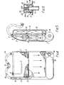
- the breathing apparatus comprises an outer casing formed by two opposed panel members 7 and 8 of dished configuration, the member 7 serving to support the reservoir 2 of refrigerant, as well as a canister 9 containing a carbon dioxide absorbing medium, and an oxygen cylinder 10.
- the member 8 serves to enclose a breathing bag 11 connected on the one hand to an outlet 12 from the canister 9, and on the other hand to an inlet 13 to the cooling tube 1.
- the other end of the cooling tube 1 is coupled to a breathing tube 14 leading to a mouthpiece 15, which mouthpiece is further coupled via an exhaust tube 16 to a conduit 17 leading to the canister 9.
- the mouthpiece 15 incorporates non-return valves, not shown, which operate in a direction such that air is inhaled from the tube 14 and exhaled to the tube 16.
- the oxygen cylinder 10 comprises a supply valve and regulator 18 of conventional type, by means of which oxygen can be supplied at a controlled rate to the breathing bag 11.
- air breathed by the wearer is recirculated through the system in the direction indicated by the arrows.
- air from the breathing bag 11, containing oxygen supplied from the cylinder 10 is inhaled via pipe 1 and breathing tube 14, and then exhaled via tube 16 and conduit 17 to the canister 9 wherein carbon dioxide is absorbed from the air by the absorbent medium present in the canister 9, before the air returns to the breathing bag 11 to be recharged with oxygen from the cylinder 10.
- the air to be breathed is cooled by the tube 1 serving as a heat exchanger as described above in the case of the device of Figs. 1 - 3.
- the temperature of the air to be breathed is thus determined by the boiling point of the refrigerant medium contained within the reservoir 2 and maintained under a predetermined vapour pressure by means of the adjustable relief valve 4.
- the sensing tube 3 connected to the relief valve 4 communicates with the volumetric centre of the reservoir 2 which, as shown more clearly in Fig. 5, is less than half filled with refrigerant medium so that the refrigerant liquid cannot itself enter the tube 3.
- valve 4 The construction of the valve 4 is illustrated in more detail Fig. 6, wherein it will be seen that the sensing tube 3 engages with a valve body 25 fitted in the wall of the reservoir 2 and providing a valve seat 26 for a valve member 24 having a stem 24A guided within a bore 22A of an adjustable valve cap 22 in screw threaded engagement with the valve body 25.
- a compression spring 23 engages between the cap 22 and the valve member 24, and thus force of the spring, and the corresponding pressure at which the valve member 24 is released from the valve seat 26 is determined by the extent to which the cap 22 is screw threaded on to the valve body 25.
- the cap 22 incorporates a vent 27 to allow escape of refrigerant gas released by the valve member 24.
- a locking screw 21 serves to enable locking of the valve cap 22 in a selected position of adjustment.
- valve member 6 The construction of the valve member 6 is substantially similar to that of the valve member 4 as illustrated in Fig. 6 with the exception that the sensing tube 3 is omitted.
Landscapes
- Health & Medical Sciences (AREA)
- Pulmonology (AREA)
- General Health & Medical Sciences (AREA)
- Business, Economics & Management (AREA)
- Emergency Management (AREA)
- Respiratory Apparatuses And Protective Means (AREA)
- Thermotherapy And Cooling Therapy Devices (AREA)
Abstract
Description
- This invention concerns improvements in or relating to breathing apparatus.
- There are two main types of breathing apparatus in use at the present time. One type consists of an air or other respirable gas supply from a cylinder controlled by a demand valve, operated by the wearer (commonly called open circuit type). In this type the full volume of each breath is taken from the cylinder. The British Standard test for breathing apparatus specifies a minute volume of breathing of 40 litres a minute (BS 4667 1974). This has been shown to accurately reflect that actually needed in practice. For practical purposes the largest size oxygen cylinder a man can carry in a breathing apparatus has 2000 litres of air in it and this charged weights some 15 kilograms. It is seen from these figures that the maximum duration of this type of breathing apparatus is 60 minutes at this flow.
- When the requirement for a breathing apparatus is for a longer duration of up to 4 hours, a second type of breathing apparatus is used. This type of apparatus, commonly referred to as the closed circuit type, consists of an oxygen cylinder or other oxygen supply feeding into a recirculating system. The circuit of this system includes a reservoir bag and a carbon dioxide absorber, together with non-return and relief valves. This system is well known and has the advantage that the oxygen supply from the cylinder can now be at the rate absorbed by the wearer's lungs and is approximately 1 - 3 litres per minute depending on activity. This means that the oxygen used for a 4 hour duration is now only 720 litres maximum (at 3 litres per minute) giving a large weight saving. The disadvantage of all known systems of this type, however, is that the absorption of carbon dioxide by an absorbent material, usually soda lime in a cannister, involves an exothermic reaction. The amount of heat produced by this reaction is of the order of 1000 calories per minute for the figures given earlier, and thus the medium breathed by the wearer of the apparatus is correspondingly heated.
- As breathing apparatus is commonly used in hot environments such as fires or mines, this heat is not easily dissipated and consequently places a physiological strain on the wearer. The British Standard test mentioned earlier specifies an inhaled oxygen temperature of less than 40°C in an ambient of 30°C 85 - 90% relative humidity. It has been shown that if this inhaled oxygen temperature could be reduced below the body temperature of 37°C, great benefit would result for the wearer, as he would now pass heat to the apparatus instead of taking heat from it. Many methods to achieve this have been tried, for example, coolers using latent heat of fusion of ice or other substances, but these to be effective are too heavy for the wearer. Evaporation of water has been also tried but as the relative humidity of the environment is high, elevated flows of oxygen are needed in combination with this, again producing too heavy an apparatus.
- It is an object of the invention to overcome at least some of the disadvantages of the known breathing apparatus referred to above by providing a simple and readily portable means of cooling the medium to be breathed, for example in a breathing apparatus of the kind wherein the breathed medium is to be recycled.
- It is a further object of the invention to provide an improved breathing apparatus incorporating such means for cooling a breathing medium.
- In accordance with the invention, a breathable medium is cooled by passing the medium through a conduit in heat exchange relationship with a reservoir containing a liquid which has a boiling point below the maximum desired temperature of the breathable medium, said reservoir being vented to allow escape of liquid vapour therefrom, whereby cooling of said breathable medium passing through said conduit is effected through a progressive boiling away of the liquid from said reservoir, and means being provided for controlling the vapour pressure within said reservoir and thus the boiling point of said medium, whereby the temperature of said medium is correspondingly controlled.
- There are available a variety of non-inflammable and non-toxic refrigerant media which satisfy the requirement for a liquid to be used in accordance with the invention, which can be stored under their own vapour pressure, and the latent heat of evaporation of which enable effective cooling of the breathable medium.
- Examples of suitable refrigerant media are:-

- The refrigerant medium and the operating pressure of the pressure release valve should be selected in such a combination as to provide for boiling-off of the liquid at an appropriate temperature of the breathable medium. The latent heat of vaporisation of the liquids referred to above is such that less than 1 kilogram of liquid is evaporated during the normal duration of the apparatus.
- In accordance with a preferred feature of the invention, the pressure release valve is manually adjustable to provide means for optionally controlling the temperature of the breathable medium. This gives the enormous advantage that the wearer of a breathing apparatus can himself set the temperature of the inhaled medium by a control on the apparatus and can vary this to suit his needs in varying ambient temperatures. For example, he can select a lower inhaled oxygen temperature in high environmental temperatures and promote body cooling. The boiling point of R11 at 2 bar absolute pressure is 45°C. This gives a blow-off value and reservoir pressure of only 15 P.S.I. (1 bar) above atmospheric pressure so that this agent alone gives a range of 23.7 - 45°C over the pressure range of 0 to 15 P.S.I. above atmospheric pressure.
- The invention further provides a cooling device for use in the method of the invention comprising a fluid flow conduit, a reservoir in heat exchange relationship with said conduit, a body of liquid contained within said reservoir, and pressure relief value means for venting said reservoir to atmosphere. The said conduit may consist of a tube or other vessel with an adequate surface area in the breathing circuit in thermal contact with the reservoir of liquid. The boiling point of the liquid may then be selected in accordance with the vapour pressure curve for this liquid and the pressure maintained in the reservoir by adjustment of the pressure relief valve which may be under the control of the wearer.
- The device in accordance with the invention can be stored fully charged ready for instant use. The reservoir can be constructed in one or more parts so that the refrigerant liquid is either inside or outside the breathing circuit tube or vessel. It can also be constructed on the principles of the "non-spill inkwell" so that it is not filled to more than 50% of its volume. The blow-off outlet is then located in the centre point of the reservoir so that the wearer can assume any position, such as head down, without loss of liquid.
- The cooling device in accordance with the invention can be incorporated as a part of a complete breathing equipment or may be adapted for adding to existing breathing apparatus. Moreover, although the device is primarily intended for use with breathing apparatus, it will be appreciated that it may also have other uses where the cooling of fluid medium is desirable.
- Figure 1 is a side view of the one embodiment of a cooling device in accordance with the invention that may be incorporated into a standard breathing apparatus circuit,
- Figure 2 is a view corresponding to Fig. 1 in the direction of the arrow X in Fig. 1,
- Figure 3 is a plan view corresponding to Fig. 2,
- Figure 4 is a front elevation, partly in section, of a breathing apparatus in accordance with the invention incorporating a cooling device,
- Figure 5 is a side elevation, partly in section, of the device shown in Fig. 4, and
- Figure 6 is a fragmentary cross section of a pressure relief valve of the kind utilised in the devices shown in Figs. 1 - 3 and Figs. 4 and 5 respectively.
- Referring to Figs. 1 - 3 of the drawings, a
tube 1 for connection into the circuit of a breathing apparatus passes through areservoir vessel 2. Thetube 1 may have fins, balls, wire wool or other means inside to increase the surface area for heat exchange with the breathable medium. Thetube 1 is set off centre so that the inner end of a filling andventing tube 3 is located in the volumetric centre of the reservoir, so that when - The breathing apparatus comprises an outer casing formed by two opposed panel members 7 and 8 of dished configuration, the member 7 serving to support the
reservoir 2 of refrigerant, as well as a canister 9 containing a carbon dioxide absorbing medium, and anoxygen cylinder 10. The member 8 serves to enclose abreathing bag 11 connected on the one hand to anoutlet 12 from the canister 9, and on the other hand to aninlet 13 to thecooling tube 1. The other end of thecooling tube 1 is coupled to abreathing tube 14 leading to amouthpiece 15, which mouthpiece is further coupled via anexhaust tube 16 to a conduit 17 leading to the canister 9. In conventional manner themouthpiece 15 incorporates non-return valves, not shown, which operate in a direction such that air is inhaled from thetube 14 and exhaled to thetube 16. - The
oxygen cylinder 10 comprises a supply valve andregulator 18 of conventional type, by means of which oxygen can be supplied at a controlled rate to thebreathing bag 11. - In the operation of the device described, air breathed by the wearer is recirculated through the system in the direction indicated by the arrows. Thus, air from the
breathing bag 11, containing oxygen supplied from thecylinder 10 is inhaled viapipe 1 andbreathing tube 14, and then exhaled viatube 16 and conduit 17 to the canister 9 wherein carbon dioxide is absorbed from the air by the absorbent medium present in the canister 9, before the air returns to thebreathing bag 11 to be recharged with oxygen from thecylinder 10. The air to be breathed is cooled by thetube 1 serving as a heat exchanger as described above in the case of the device of Figs. 1 - 3. The temperature of the air to be breathed is thus determined by the boiling point of the refrigerant medium contained within thereservoir 2 and maintained under a predetermined vapour pressure by means of the adjustable relief valve 4. As in the case of the embodiment of Figs. 1 - 3, thesensing tube 3 connected to the relief valve 4 communicates with the volumetric centre of thereservoir 2 which, as shown more clearly in Fig. 5, is less than half filled with refrigerant medium so that the refrigerant liquid cannot itself enter thetube 3. - The construction of the valve 4 is illustrated in more detail Fig. 6, wherein it will be seen that the
sensing tube 3 engages with avalve body 25 fitted in the wall of thereservoir 2 and providing avalve seat 26 for avalve member 24 having astem 24A guided within abore 22A of anadjustable valve cap 22 in screw threaded engagement with thevalve body 25. Acompression spring 23 engages between thecap 22 and thevalve member 24, and thus force of the spring, and the corresponding pressure at which thevalve member 24 is released from thevalve seat 26 is determined by the extent to which thecap 22 is screw threaded on to thevalve body 25. Thecap 22 incorporates avent 27 to allow escape of refrigerant gas released by thevalve member 24. A lockingscrew 21 serves to enable locking of thevalve cap 22 in a selected position of adjustment. - The construction of the
valve member 6 is substantially similar to that of the valve member 4 as illustrated in Fig. 6 with the exception that thesensing tube 3 is omitted.
Claims (15)
Priority Applications (2)
| Application Number | Priority Date | Filing Date | Title |
|---|---|---|---|
| EP19840300140 EP0148543B1 (en) | 1984-01-10 | 1984-01-10 | Improvements to breathing apparatus |
| DE8484300140T DE3466934D1 (en) | 1984-01-10 | 1984-01-10 | Improvements to breathing apparatus |
Applications Claiming Priority (1)
| Application Number | Priority Date | Filing Date | Title |
|---|---|---|---|
| EP19840300140 EP0148543B1 (en) | 1984-01-10 | 1984-01-10 | Improvements to breathing apparatus |
Publications (2)
| Publication Number | Publication Date |
|---|---|
| EP0148543A1 true EP0148543A1 (en) | 1985-07-17 |
| EP0148543B1 EP0148543B1 (en) | 1987-10-28 |
Family
ID=8192522
Family Applications (1)
| Application Number | Title | Priority Date | Filing Date |
|---|---|---|---|
| EP19840300140 Expired EP0148543B1 (en) | 1984-01-10 | 1984-01-10 | Improvements to breathing apparatus |
Country Status (2)
| Country | Link |
|---|---|
| EP (1) | EP0148543B1 (en) |
| DE (1) | DE3466934D1 (en) |
Cited By (4)
| Publication number | Priority date | Publication date | Assignee | Title |
|---|---|---|---|---|
| EP0310735A1 (en) * | 1983-06-17 | 1989-04-12 | The Boeing Company | Polysulfone and polyethersulfone oligomers |
| US4871475A (en) * | 1985-10-07 | 1989-10-03 | The Boeing Company | Polysulfone and polyethersulfone oligomers |
| US5269293A (en) * | 1990-09-13 | 1993-12-14 | Dragerwerk Aktiengesellschaft | Cooling device for cooling breathing gas in a respiratory protection device |
| EP2818204A1 (en) | 2013-06-25 | 2014-12-31 | Dräger Safety AG & Co. KGaA | Cooling device for chemical protection suits and/or closed-circuit breathing apparatuses |
Citations (3)
| Publication number | Priority date | Publication date | Assignee | Title |
|---|---|---|---|---|
| DE881155C (en) * | 1951-08-15 | 1953-06-29 | Hermann Dr Med Bruener | Breathing apparatus for working in hot places |
| GB733473A (en) * | 1951-01-10 | 1955-07-13 | Nat Res Dev | Improvements relating to breathing apparatus |
| GB1194944A (en) * | 1967-05-24 | 1970-06-17 | Air Liquide | Improvements in or relating to Respiratory Apparatus |
-
1984
- 1984-01-10 DE DE8484300140T patent/DE3466934D1/en not_active Expired
- 1984-01-10 EP EP19840300140 patent/EP0148543B1/en not_active Expired
Patent Citations (3)
| Publication number | Priority date | Publication date | Assignee | Title |
|---|---|---|---|---|
| GB733473A (en) * | 1951-01-10 | 1955-07-13 | Nat Res Dev | Improvements relating to breathing apparatus |
| DE881155C (en) * | 1951-08-15 | 1953-06-29 | Hermann Dr Med Bruener | Breathing apparatus for working in hot places |
| GB1194944A (en) * | 1967-05-24 | 1970-06-17 | Air Liquide | Improvements in or relating to Respiratory Apparatus |
Cited By (4)
| Publication number | Priority date | Publication date | Assignee | Title |
|---|---|---|---|---|
| EP0310735A1 (en) * | 1983-06-17 | 1989-04-12 | The Boeing Company | Polysulfone and polyethersulfone oligomers |
| US4871475A (en) * | 1985-10-07 | 1989-10-03 | The Boeing Company | Polysulfone and polyethersulfone oligomers |
| US5269293A (en) * | 1990-09-13 | 1993-12-14 | Dragerwerk Aktiengesellschaft | Cooling device for cooling breathing gas in a respiratory protection device |
| EP2818204A1 (en) | 2013-06-25 | 2014-12-31 | Dräger Safety AG & Co. KGaA | Cooling device for chemical protection suits and/or closed-circuit breathing apparatuses |
Also Published As
| Publication number | Publication date |
|---|---|
| EP0148543B1 (en) | 1987-10-28 |
| DE3466934D1 (en) | 1987-12-03 |
Similar Documents
| Publication | Publication Date | Title |
|---|---|---|
| US4586500A (en) | Breathing apparatus | |
| US5111809A (en) | Breathing system | |
| US4168706A (en) | Portable breathing system | |
| JP5095634B2 (en) | Breathing apparatus | |
| US3208449A (en) | Compact walk-around rebreathing device | |
| US4403608A (en) | Pressure gas ventilated protective suit and method of operating the suit | |
| US5511542A (en) | Lox breathing system with gas permeable-liquid impermeable heat exchange and delivery hose | |
| GB1581588A (en) | Protective suits | |
| US3805780A (en) | Mine rescue breathing apparatus | |
| US5361591A (en) | Portable life support system | |
| US4154234A (en) | Breathing bag system for closed circuit breathing apparatus | |
| JPS6224107B2 (en) | ||
| US4314566A (en) | Air cooler for self-contained breathing system | |
| US4793340A (en) | Breathing system for divers | |
| US4635629A (en) | Breathing apparatus | |
| US3913576A (en) | Breathing apparatus | |
| EP0148543B1 (en) | Improvements to breathing apparatus | |
| US4016876A (en) | Breathing apparatus | |
| US3366107A (en) | Apparatus for supplying breathable gas from oxygen in liquid form | |
| SU1722222A3 (en) | Divers respiration system | |
| JPS5946615B2 (en) | breathing apparatus | |
| JPS5924035B2 (en) | breathing apparatus | |
| US4020833A (en) | Oxygen source for human respiration requirements | |
| US5537995A (en) | Breathing system having breathing bag and supplemental gas dosing controls | |
| EP0158498A2 (en) | Closed circuit compressed oxygen breathing device |
Legal Events
| Date | Code | Title | Description |
|---|---|---|---|
| PUAI | Public reference made under article 153(3) epc to a published international application that has entered the european phase |
Free format text: ORIGINAL CODE: 0009012 |
|
| AK | Designated contracting states |
Designated state(s): AT BE CH DE FR GB IT LI LU NL SE |
|
| RBV | Designated contracting states (corrected) |
Designated state(s): DE FR GB IT SE |
|
| 17P | Request for examination filed |
Effective date: 19851211 |
|
| 17Q | First examination report despatched |
Effective date: 19870130 |
|
| GRAA | (expected) grant |
Free format text: ORIGINAL CODE: 0009210 |
|
| AK | Designated contracting states |
Kind code of ref document: B1 Designated state(s): DE FR GB IT SE |
|
| ITF | It: translation for a ep patent filed | ||
| REF | Corresponds to: |
Ref document number: 3466934 Country of ref document: DE Date of ref document: 19871203 |
|
| ET | Fr: translation filed | ||
| PLBI | Opposition filed |
Free format text: ORIGINAL CODE: 0009260 |
|
| 26 | Opposition filed |
Opponent name: DRAEGERWERK AG Effective date: 19880701 |
|
| PGFP | Annual fee paid to national office [announced via postgrant information from national office to epo] |
Ref country code: GB Payment date: 19890110 Year of fee payment: 6 |
|
| PG25 | Lapsed in a contracting state [announced via postgrant information from national office to epo] |
Ref country code: SE Effective date: 19890111 |
|
| PG25 | Lapsed in a contracting state [announced via postgrant information from national office to epo] |
Ref country code: DE Effective date: 19891003 |
|
| RDAG | Patent revoked |
Free format text: ORIGINAL CODE: 0009271 |
|
| STAA | Information on the status of an ep patent application or granted ep patent |
Free format text: STATUS: PATENT REVOKED |
|
| 27W | Patent revoked |
Effective date: 19891027 |
|
| GBPR | Gb: patent revoked under art. 102 of the ep convention designating the uk as contracting state | ||
| EUG | Se: european patent has lapsed |
Ref document number: 84300140.5 Effective date: 19891205 |