EP0148535A1 - Object sorting system - Google Patents
Object sorting system Download PDFInfo
- Publication number
- EP0148535A1 EP0148535A1 EP84201932A EP84201932A EP0148535A1 EP 0148535 A1 EP0148535 A1 EP 0148535A1 EP 84201932 A EP84201932 A EP 84201932A EP 84201932 A EP84201932 A EP 84201932A EP 0148535 A1 EP0148535 A1 EP 0148535A1
- Authority
- EP
- European Patent Office
- Prior art keywords
- columns
- features
- master
- binary
- run
- Prior art date
- Legal status (The legal status is an assumption and is not a legal conclusion. Google has not performed a legal analysis and makes no representation as to the accuracy of the status listed.)
- Granted
Links
- 238000000605 extraction Methods 0.000 claims description 8
- 238000005070 sampling Methods 0.000 claims description 4
- 108010076504 Protein Sorting Signals Proteins 0.000 claims description 2
- 238000012360 testing method Methods 0.000 abstract description 2
- 238000000034 method Methods 0.000 description 28
- 230000008569 process Effects 0.000 description 24
- 230000000694 effects Effects 0.000 description 5
- 230000006870 function Effects 0.000 description 5
- 239000000203 mixture Substances 0.000 description 3
- 238000012545 processing Methods 0.000 description 3
- 238000006073 displacement reaction Methods 0.000 description 2
- 230000008707 rearrangement Effects 0.000 description 2
- 230000009467 reduction Effects 0.000 description 2
- 238000000926 separation method Methods 0.000 description 2
- 230000007704 transition Effects 0.000 description 2
- 230000009471 action Effects 0.000 description 1
- 230000008859 change Effects 0.000 description 1
- 230000006835 compression Effects 0.000 description 1
- 238000007906 compression Methods 0.000 description 1
- 238000009833 condensation Methods 0.000 description 1
- 230000005494 condensation Effects 0.000 description 1
- 238000012937 correction Methods 0.000 description 1
- 238000000151 deposition Methods 0.000 description 1
- 238000013461 design Methods 0.000 description 1
- 238000003384 imaging method Methods 0.000 description 1
- 230000008676 import Effects 0.000 description 1
- 238000010348 incorporation Methods 0.000 description 1
- 238000003780 insertion Methods 0.000 description 1
- 230000037431 insertion Effects 0.000 description 1
- 238000007689 inspection Methods 0.000 description 1
- 230000003287 optical effect Effects 0.000 description 1
- 238000007747 plating Methods 0.000 description 1
- 230000000063 preceeding effect Effects 0.000 description 1
- 230000004044 response Effects 0.000 description 1
Images




Classifications
-
- B—PERFORMING OPERATIONS; TRANSPORTING
- B07—SEPARATING SOLIDS FROM SOLIDS; SORTING
- B07C—POSTAL SORTING; SORTING INDIVIDUAL ARTICLES, OR BULK MATERIAL FIT TO BE SORTED PIECE-MEAL, e.g. BY PICKING
- B07C5/00—Sorting according to a characteristic or feature of the articles or material being sorted, e.g. by control effected by devices which detect or measure such characteristic or feature; Sorting by manually actuated devices, e.g. switches
- B07C5/36—Sorting apparatus characterised by the means used for distribution
- B07C5/363—Sorting apparatus characterised by the means used for distribution by means of air
- B07C5/365—Sorting apparatus characterised by the means used for distribution by means of air using a single separation means
-
- B—PERFORMING OPERATIONS; TRANSPORTING
- B07—SEPARATING SOLIDS FROM SOLIDS; SORTING
- B07C—POSTAL SORTING; SORTING INDIVIDUAL ARTICLES, OR BULK MATERIAL FIT TO BE SORTED PIECE-MEAL, e.g. BY PICKING
- B07C5/00—Sorting according to a characteristic or feature of the articles or material being sorted, e.g. by control effected by devices which detect or measure such characteristic or feature; Sorting by manually actuated devices, e.g. switches
- B07C5/02—Measures preceding sorting, e.g. arranging articles in a stream orientating
-
- B—PERFORMING OPERATIONS; TRANSPORTING
- B07—SEPARATING SOLIDS FROM SOLIDS; SORTING
- B07C—POSTAL SORTING; SORTING INDIVIDUAL ARTICLES, OR BULK MATERIAL FIT TO BE SORTED PIECE-MEAL, e.g. BY PICKING
- B07C5/00—Sorting according to a characteristic or feature of the articles or material being sorted, e.g. by control effected by devices which detect or measure such characteristic or feature; Sorting by manually actuated devices, e.g. switches
- B07C5/04—Sorting according to size
- B07C5/10—Sorting according to size measured by light-responsive means
Definitions
- the invention relates to a system for sorting objects from amongst a mixture of objects of a limited number of kinds. More particularly, it relates to a sorting system in which the objects are presented for inspection and classification in a limited number of possible orientations. Such a system may be used for sorting components into specific orientation for further processing or for automatic assembly into larger units.
- the orientation of components can be maintained from a previous process, the components being loaded into a magazine. But processes such as deburring, plating or even bulk storage may lead to randomly orientated components.
- a vision-based system may be used to view the components and to make a sorting decision based on a computer processing of the image provided by such a vision system.
- a vision system is described in the article "A practical vision system for use with bowl feeders", Proceedings of the First International Conference on Assembly Automation, A.J. Cronshaw et al, pages 265-274, Brighton, England, March 1980.
- the component is moved transversely relative to a linear array of photodetectors which are scanned repetitively to provide a binarised picture of the component.
- the system is shown good components and the binarized picture is displayed to a programmer with knowledge of the component.
- the invention provides an object sorting device comprising means for scanning successive objects each in a raster to derive a raster waveform of each object, means for binarizing the waveform into a picture comprising rows and columns of binary pixels, feature extraction means for extracting selected features from the binary picture, storage means for storing a master set of features and comparison means for comparing the selected features with the master set of features to derive a binary object sorting signal, characterised in that the system comprises means for deriving the master set of features by scanning a reference object, in that said feature extraction means comprise run counting means for counting a run of successive identical pixel columns and for outputting only those runs having a predetermined minimum length to form selected features, and in that the sorting signal is derived from a comparison of the succession of features of the master and unknown sets.
- a feature is defined as a run of successive identical pixel columns and the minimum run length is preferably two columns.
- the device may be characterised in that where a first run of a first identity of columns is followed by a second run of a second identity of columns and the first and second runs are separated by two intervening columns having in sequence the second and the first identity, these two intervening columns are interchanged and each joined with the run of columns having the same identity. Errors at the junction between two long consecutive runs due to scanning errors are thereby reduced.
- the device may be further characterised in that said feature extraction means have sequence warping control means to ignore non-conforming pixel columns of the outputted object pixel colums and/or the stored master pixel columns for the comparison. This has the effect of further reducing scanning errors.
- the device may also be characterised in that said feature extraction means comprise a signature forming means connected to an output of said counting means for compressing outputted run lengths of identical pixel columns between predetermined respective limits into predetermined signature columns to be compared to a set of master signature columns. This has the effect of reducing the length of the master signature, or master set of identities, and facilitating the comparison of master and unknown signatures.
- composition of master signature can be improved in such a sorting system which is characterised in that the succession of identities comprising the master set is derived from a plurality of successions obtained by scanning the plurality of reference objects, in that the first succession is taken as a first version of the master set, in that the following succession is compared with the first version, new identities present in the following succession being inserted between corresponding runs of identities in the two successions to form a second version of the master set, and in that each following succession of the plurality of successions is compared with the preceding version of the master set in like manner to produce a final version of the master set.
- the means for scanning the object in a raster may comprise one of the known forms of television camera.
- the video waveform from the camera is thresholded and sampled at intervals along each line of the television raster to provide the binarized picture.
- the components are often delivered in fairly steady linear motion along a track from, for example, a bowl feeder.
- an object sorting system in accordance with the invention may be characterised in that the means for scanning the object in a raster comprise means for moving the object linearly relative to a transverse linear array of photodetectors, the outputs of the photodetectors being sampled in sequence along the array at intervals throughout the relative motion to provide the raster waveform, and in that the means for binarizing the waveform comprise means for applying the output of each photodetector sample to a threshold level and for assigning one binary value to the sample if it equals or exceeds the threshold level and for assigning the other binary value if it is less than the threshold level, one sampling of the array giving rise to one column of binary picture elements and the sampling of the array throughout the linear relative motion giving rise to rows of binary picture elements.
- FIG. 1 there is shown a portion 1 of the curved track of a vibratory bowl component feeder.
- Such feeders are well known in the component handling art and will not be described further. Reference may be had to the textbook "Handbook of feeding and orienting techniques for small parts" by G. Boothroyd, University of Massachusetts, for a description of bowl feeders.
- the action of the bowl feeder presents a succession of components or objects 18, in random orientation, sliding along the track against a fence 2.
- the surface of the track is inclined downwards toward the junction with the fence so that the object is maintained in registration with the fence.
- the fence defines the orientation of the component and its position across the track.
- the length of the track is inclined downwardly in the desired direction of motion of the objects. This need not be so since vibratory-feeders can be designed to move objects up a sloping track.
- a slot 3 is provided in the track illuminated from below by a light box 4.
- a camera 5, comprising a lens 6 and a linear array of photodetectors 7, is provided for scanning the length of the slot and the thickness of the fence, which is increased locally to extend beyond the end of the image of the linear array.
- the portion 1 of the track in the locality of the slot 3 is mechanically separate from the remainder of the track.
- Figure 2 shows this portion of the track in more detail.
- the track portion 1 is mounted upon a linear vibratory feeder 8 which imports a linear vibratory motion to the track portion 1 in the direction 10 along its length.
- the track portion 11 of the bowl feeder (not shown) is arranged to feed components onto the portion 1 and scanned components are fed to the track portion 12.
- the vibrator 8 is fed from a variable transformer 9.
- the amplitude of the motion 10 is adjusted so that the components are speeded up on landing on portion 1 so that they are separated, allowing each component to be scanned separately.
- the inclinations 13 and 14 of the track to the horizontal H are shown which maintain a component against the ledge and moving from right to left.
- the track of the bowl feeder alone may be used to produce component separation by incorporating slope changes in the track.
- a hump for example, will act to hold components momentarily, each component accelerating away from the others as it clears the hump.
- the camera 5 is shown only schematically as a lens 6 which images the plane of the slot 3 onto the linear array of photodetectors 7.
- the array comprises a 128 photodiode linear array sensor, for example a Reticon (Trade Mark) type RL128G.
- the lens focal length and the imaging distances are chosen in this example so that the detector separation, as imaged on the track, is 0.4mm so that 64 detectors cover a slot length of 25.6mm.
- some 64 consecutive photodiodes are sufficient to cover the maximum object width which will be encountered. It should be noted that the scan need not cover the entire vertical dimension of the object.
- the top of the object remote from the fence may contain little detail which renders the orientation of the component distinctive and may be discarded by a scan which falls short of the top of the object.
- the clock period of the array is 5us, and the time between scans is 4ms. Most of the time between scans is used to process the results of each scan.
- each photodiode output corresponding to a brightness midway between open and obscured slot.
- the output of each photodiode is therefore reduced to a binary signal, WHITE or BLACK.
- the photodiodes are spaced apart and scans of the photodiode array take place after a finite movement of the object, the array and object movement result in a binarized picture of the whole component comprising columns of binary picture elements parallel to the array length.
- the columns of binary picture elements for the whole component are fed to a controller 15, comprising a microprocessor, within which the picture is analysed and a decision made, as will be described later, whether to accept or reject the component.
- a controller 15 comprising a microprocessor, within which the picture is analysed and a decision made, as will be described later, whether to accept or reject the component.
- an air valve 16 is opened and a jet of air through nozzle 17 is directed to remove a rejected component from the track, depositing it back in the bowl of the feeder whence it will re-emerge later along track 11, but possibly with a different orientation. Given time, all the components in the bowl will pass along track 12 with a common, desired, orientation.
- controller 15 in producing the binary sorting decision from the camera output will first be described in terms of the functions provided by the microprocessor in the controller. An outline guide to the programming of the microprocessor needed to realise these functions will then be given.
- the first function of the controller is to process the camera output to determine the position of the fence in the column of binary picture elements provided by a scan of the linear array.
- the camera is set so that the first detector of the array corresponds to a point inside the side fence of the track. Consequently the first set of detectors, up to that detector corresponding to the fence, sees black. The remainder see white except when a component passes.
- the number along the array of the first detector seeing white and to be used as the first of the column is held in store and if ever the detector preceeding that one sees white the number is reduced by one.
- the number is occasionally increased by one, for example, once for every 256 scans, and if no shift of the camera has occurred this increase of the detector number would be cancelled in the next scan, as described above.
- the number of detectors required is 64 plus an allowance for the accuracy of the initial positioning of the camera and its movement during use.
- the processor takes the camera output for the next 64 picture elements after the transition near the fence.
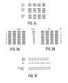
- the next function is to condense the 64 picture elements (pixels) to 16 states by taking them in blocks of 4 as shown in Figure 3a, in which the column pixels are laid out in a horizontal line for compactness. If in a block the majority are black (B) then the state is black and similarly for white (W). If there are equal numbers of black and white pixels, the state is 'don't care' (X).
- a column of condensed black/white states will be referred to as a black/white pattern.
- the arrival of a component at the slot is detected by the processor as the presence of any black states in a column. This condition initiates the cycle of events for that component.
- the controller contains no information on the components to be sorted. Consequently a learning mode is first required in which information on the wanted and unwanted orientations of the component is acquired.
- the learning mode contains three phases. In the first and last phases components are fed past the slot in the correct orientation and in the second phase in other orientations. In the first two phases the processor forms a reference table of black/white patterns representing columns of pixels which are distinguishable from one another by the order and number of black/white states which they contain. Each entry in this table is allocated a distinctive identity. In the last phase a master signature is formed of the correct orientation of the component. This signature comprises a compressed average sequence of identities which are obtained as the component passes the slot.
- the condensed black/white patterns are stored in a first table in which the number of times that that pattern has appeared is also recorded. At the start of learning this table is empty. Following each scan, the condensed pattern obtained is compared with any existing members of the table. If an exact match is found the count for that pattern is incremented by one, otherwise the new pattern is added to the table. The beginning of such a first table is shown in Figure 3b. This pattern storing continues until a predefined number of components have been scanned. Then, these patterns are taken in order of frequency of occurrence and modified to introduce a small amount of tolerance for subsequent matching processes, for example, during sorting. Generally this is done by introducing 'don't care' conditions where there are transitions between black and white.
- Figure 3c Examples of this are shown in Figure 3c.
- a condensed pattern contains a pair of blacks or a pair of whites set in a contrasting background, such a pair would be removed and replaced by a run of four 'don't care' states.
- This is avoided in Figure 3c by producing two toleranced patterns for each original pattern. In each toleranced pattern only one or the other member of such a pair has the tolerancing operation applied to it.
- the new patterns are stored in a new second table, Figure 3d, together with an identifier corresponding to the position of the source pattern in the first table.
- the toleranced patterns are stored in the same order in the new table, i.e. most frequent first.
- the second table reaches a predetermined length, for example, twenty entries.
- the number of entries in the first table depends upon the complexity of the component and fifty to two hundred entries is common in a typical system.
- the sequence of black/white patterns as scanned and condensed bears a resemblance to the component geometry.
- the sequence in the tables may bear very little resemblance to the component geometry since identical patterns may occur in widely separated parts of the component.
- the components are fed in the wrong orientations.
- simply reversing the direction of the feed will produce the same patterns as before, but in the reverse order, if the component has the same points of contact with the guiding surface at the side of the feeder.
- a new set of patterns will generally be obtained.
- the process continues as before and a new list is formed as in the first table. Again these are modified to introduce tolerances and the resulting patterns are added to the end of the second table. If a pattern obtained from a wrong orientation matches any of the existing patterns obtained from correct orientations it is ignored. A predetermined number of non-matching patterns, for example, twelve, are added to the table.
- the identifiers recorded with the patterns in this second part of the table include a code to show that they were obtained from components having wrong orientations and this is used to apply a penalty when scoring the matches during sorting.
- each black/white pattern obtained is compared to the table of thirty two patterns previously formed.
- a pattern match is indicated when every black and every white state in an entry in the reference table is matched by a correspondingly positioned state in the black/white pattern offered. No match is necessary for 'don't care' states.
- the matching attempts are started from the top of the reference table, i.e. the most frequently occurring black/white pattern, and stop with the first successful match, although others may be possible further down the table. If no match is found the pattern offered is rejected.
- its identity, A,B,C, etc is added to a list in the order in which it occurs as the component passes the slot.
- a list of identities is obtained, referred to as a long signature of the component.
- Figure 3e shows a typical long signature.
- the length of the long signature is then reduced to give a short signature.
- the long signature will contain runs of the same identifying codes, or pixel columns. If, after some rearrangement as described below, these runs are shorter than a preset fraction, e.g. 2%, of the total signature length, they are removed from the signature. In the rest, each run is represented in the short signature by one entry of the same identifying code but this one entry is repeated if the run exceeds another preset fraction, e.g. 10%. A run of 25X, for example, would result in three entries, Figure 3(e). Before deleting short runs the following rearrangements are made to ensure a more realistic reduction in the presence of noise.
- the short signature obtained from the next component scanned is then compared and merged with the master signature. Normally the two are not identical and the second signature may have codes, or identities, not present in the master, have codes missing and have a different overall length.
- the comparison and merging are performed in two stages, see Figure 3f. First, an attempt is made to find blocks of at least three codes which appear in both signatures. The search starts from one end of the signatures and, with these ends aligned, the search for matching blocks is made.
- the learning process is automatic and builds up to the master signature from the scanned patterns by the use of these relatively simple rules. As a result if the learning process is repeated slight differences can occur in the lists of patterns and there may be slight changes in the master signatures obtained. These variations can arise from slight differences in the components used for the learning phase, their velocities and their positions on the track. Even so, there is little effect on the discrimination obtained during sorting between different components or between components in the right and wrong orientations.
- a reference table of black/white patterns from components in the desired and unwanted orientations has been built up.
- a master signature of the component in the desired orientation has been formed comprising a shortened version of the average sequence of black/white patterns which occur as the component passes the scanned slot.
- the controller is now set,into the sorting mode and a succession of components in various orientations scanned.
- the 64 black/white pixels from each column scan are reduced to 16 states as described with reference to Figure 3a.
- Figure 3h shows a part of the reference table in the top four rows with codes, while the bottom five rows show typical condensed scans obtained together with the code matches assigned to them.
- the identity, or code, of columns is obtained and a long signature for each component built up. The long signature is compressed to s short signature as in the learning mode.
- the short signature is now compared with the master short signature. As in the comparison of signatures in the learning node, the two are not normally identical.
- the measure of the degree of match between master and unknown signatures which is used is the percentage of codes in the unknown signature which match the naster in the corresponding order, related to the total number of codes in the unknown signature.
- the two stages of matching of the learning mode, described above with reference to Figure 3f are again used, but there is no attempt to insert new codes.
- the final matching score is converted to a percentage of the total number ot codes in the unknown signature and.if adequate then the component is accepted as being in the required orientation.
- Figure 3(g) shows an example of two block matches followed by four remaining matches making a total of 11 code matches in 13 codes, given an 84% match. Discrimination against incorrectly orientated components is improved using the fact that the reference list of black/white patterns includes some which will occur only when the component is in the incorrect orientation. In consequence these will appear in the signatures obtained from such components and, in calculating the matching score, are given a large negative value, e.g. -5.
- Figures 3j and 3k which correspond to Figures 3a and 3h respectively, show how the effect of a 'don't care' state is achieved.
- Figure 3j two condensed words, a 'black' word and a 'white' word are formed from each column.
- a group of four states containing either three or four blacks is condensed to a black or '1' in the 'black' word.
- Figure 3k shows how each identity is actually a pair of words, the 'black' word and the 'white' word.
- corresponding words are compared. The rule for a match is that for every '1' in the reference words the corresponding bit in the corresponding word of the scanned pair must be '1'. Zeros in the reference words are ignored in finding a match. This allows tolerance for small variations in the position of the objects with respect to the fence. Word pairs which find no match are ignored.
- the microprocessor used as the basis of the controller may be a single board of the type currently available on the market using 16 bit data handling. At least 1500 words of read only memory (ROM) and 2500 words of random access memory (RAM) are needed. A Philips P870 is suitable. An interface is required to the linear array camera and to the air valve for deflecting components. Control buttons are provided for setting the controller into learn and sort modes.
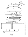
- FIGs 4,5 and 6 give an outline guide to the programming of the microprocessor.
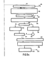
- Figure 4 shows the basic cycle of operation of the sorter. Initially an instruction would have been given to start a learning cycle by pushing the appropriate button on the controller. Consequently on reaching the box 'LEARN' the process will move to the process shown in Figure 6. At the end of the learning phase the mode is set to SORT with the result that on reaching 'Which mode?' the process shown in Figure 5 will be followed.
- the sorting flowchart the reduction of the list of identities and the matching of the signature uses the process described above.
- Figure 6 shows the flowchart for learning.
- phases 1 and 2 the component is fed in the correct and incorrect orientations respectively to enable the system to learn the types of patterns that occur and their frequency of occurrence.
- phase 3 the component has to be fed in the correct orientation and the list of patterns now in a stored called REFERENCE are used to generate the long and then the short signatures.
- BW This file is condensed into a store called CAT after each component has passed. If a fast processor is used it might be possible to enter the words directly into CAT.
- the toleranced list IND is formed from CAT.
- phase 3 a long signature for each component is formed in a store called LIST.
- LIST Each word of LIST consists of the identity and the number of consecutive occurrences of that identity.
- LIST is converted to the short signature in a store SIG, and merged with the master signature being formed in a store ITEM.
- the recognition process used in the sorter described above does not explicitly use the existence of holes, edges or other specific features. Also, it does not rely upon a priori knowledge of particular dimensions of the object. Instead it develops a viei of the object which incorporates both these aspects in a more general way. It requires no guidance or assistance from the operator except for the feeding of a few components in the require, and wrong orientations.
- This more general view of an object which is provided by the invention could be used in sorting dissimilar objects.
- a reference table of black/white patterns could be developed for each of the dissimilar objects, each object making a contribution to the negative fit part of the reference table of the other objects.
- a generalised recognition and classification process is provided applicable in those cases in which the objects or characters are presented in one or only a few well defined orientations.
- the camera comprised a linear array of photodiodes moving transversely relative to the object to scan the field within which the object is located.
- a television camera may be used, avoiding the need for relative movement.
- the video output of the camera is then thresholded and sampled at discrete intervals along the lines of the television raster to produce the rows of the binarized picture, the columns being provided by corresponding samples in the lines.
- the television camera may be used when it is convenient to 'freeze' the object with only one frame scan of the raster.
- the lines of the television raster may be used as the columns of the present invention, the frame scan of the raster providing the effect of component motion.
- the reference table and the master signature could be stored in an electrically erasable programmable read only memory (EEPROM) so that this information is not lost when the system is switched off.
- EEPROM electrically erasable programmable read only memory
- the tables and signatures of several different components could be built up gradually, but accessed immediately without need for learning when there is a change in the component to be sorted.
Landscapes
- Image Analysis (AREA)
- Sorting Of Articles (AREA)
- Length Measuring Devices By Optical Means (AREA)
- Investigating Materials By The Use Of Optical Means Adapted For Particular Applications (AREA)
Abstract
Description
- The invention relates to a system for sorting objects from amongst a mixture of objects of a limited number of kinds. More particularly, it relates to a sorting system in which the objects are presented for inspection and classification in a limited number of possible orientations. Such a system may be used for sorting components into specific orientation for further processing or for automatic assembly into larger units.
- In some cases, the orientation of components can be maintained from a previous process, the components being loaded into a magazine. But processes such as deburring, plating or even bulk storage may lead to randomly orientated components. Mechanical systems exist for orientated feeding, such as known vibratory bowl feeders or rotating drums. However the output tracks and component deflection devices of such systems have to be specially designed for each component.
- To avoid special track and deflector design a vision-based system may be used to view the components and to make a sorting decision based on a computer processing of the image provided by such a vision system. Such a system is described in the article "A practical vision system for use with bowl feeders", Proceedings of the First International Conference on Assembly Automation, A.J. Cronshaw et al, pages 265-274, Brighton, England, March 1980. In this system, the component is moved transversely relative to a linear array of photodetectors which are scanned repetitively to provide a binarised picture of the component. In use, the system is shown good components and the binarized picture is displayed to a programmer with knowledge of the component. Using a light pen, specific features are selected for incorporation in a set of templates which are subsequently used for testing further components of unknown quality. It is a disadvantage that a skilled programmer is required. It is an object of the invention to provide an object sorting system in which it is only necessary to present examples of desired and unwanted objects to the system in a learning mode, after which sorting can be carried out, without the operator having any knowledge of the object features.
- The invention provides an object sorting device comprising means for scanning successive objects each in a raster to derive a raster waveform of each object, means for binarizing the waveform into a picture comprising rows and columns of binary pixels, feature extraction means for extracting selected features from the binary picture, storage means for storing a master set of features and comparison means for comparing the selected features with the master set of features to derive a binary object sorting signal, characterised in that the system comprises means for deriving the master set of features by scanning a reference object, in that said feature extraction means comprise run counting means for counting a run of successive identical pixel columns and for outputting only those runs having a predetermined minimum length to form selected features, and in that the sorting signal is derived from a comparison of the succession of features of the master and unknown sets. A feature is defined as a run of successive identical pixel columns and the minimum run length is preferably two columns.
- The device may be characterised in that where a first run of a first identity of columns is followed by a second run of a second identity of columns and the first and second runs are separated by two intervening columns having in sequence the second and the first identity, these two intervening columns are interchanged and each joined with the run of columns having the same identity. Errors at the junction between two long consecutive runs due to scanning errors are thereby reduced.
- The device may be further characterised in that said feature extraction means have sequence warping control means to ignore non-conforming pixel columns of the outputted object pixel colums and/or the stored master pixel columns for the comparison. This has the effect of further reducing scanning errors.
- The device may also be characterised in that said feature extraction means comprise a signature forming means connected to an output of said counting means for compressing outputted run lengths of identical pixel columns between predetermined respective limits into predetermined signature columns to be compared to a set of master signature columns. This has the effect of reducing the length of the master signature, or master set of identities, and facilitating the comparison of master and unknown signatures.
- The composition of master signature can be improved in such a sorting system which is characterised in that the succession of identities comprising the master set is derived from a plurality of successions obtained by scanning the plurality of reference objects, in that the first succession is taken as a first version of the master set, in that the following succession is compared with the first version, new identities present in the following succession being inserted between corresponding runs of identities in the two successions to form a second version of the master set, and in that each following succession of the plurality of successions is compared with the preceding version of the master set in like manner to produce a final version of the master set.
- The means for scanning the object in a raster may comprise one of the known forms of television camera. In this event the video waveform from the camera is thresholded and sampled at intervals along each line of the television raster to provide the binarized picture. But in component sorting systems the components are often delivered in fairly steady linear motion along a track from, for example, a bowl feeder. In this event, an object sorting system in accordance with the invention may be characterised in that the means for scanning the object in a raster comprise means for moving the object linearly relative to a transverse linear array of photodetectors, the outputs of the photodetectors being sampled in sequence along the array at intervals throughout the relative motion to provide the raster waveform, and in that the means for binarizing the waveform comprise means for applying the output of each photodetector sample to a threshold level and for assigning one binary value to the sample if it equals or exceeds the threshold level and for assigning the other binary value if it is less than the threshold level, one sampling of the array giving rise to one column of binary picture elements and the sampling of the array throughout the linear relative motion giving rise to rows of binary picture elements.
- It is a feature of the method of processing the image provided by the linear array camera that the compressed signatures developed are relatively insensitive to the speed changes of any one object while it is being scanned and also to differences in speed between objects.
- An embodiment of the invention, in which a collection of identical objects are binary sorted into a preferred orientation and all other orientations will now be described by way of example, with reference to the accompanying drawings, in which:-
- Figure 1 shows a schematic perspective view of the optical, mechanical and electronic arrangements of an object orientation sorter,
- Figure 2 shows a more detailed view of the sorter in the vicinity of the scanned slot,
- Figures 3a to 3k inclusive show the binary patterns derived during scanning, learning and sorting objects, and
- Figures 4,5 and 6 show flow charts as an outline guide to the programming of the microprocessor needed to realise learning and sorting of components.
- Referring to Figure 1 there is shown a
portion 1 of the curved track of a vibratory bowl component feeder. Such feeders are well known in the component handling art and will not be described further. Reference may be had to the textbook "Handbook of feeding and orienting techniques for small parts" by G. Boothroyd, University of Massachusetts, for a description of bowl feeders. The action of the bowl feeder presents a succession of components orobjects 18, in random orientation, sliding along the track against afence 2. The surface of the track is inclined downwards toward the junction with the fence so that the object is maintained in registration with the fence. Thus the fence defines the orientation of the component and its position across the track. Also, the length of the track is inclined downwardly in the desired direction of motion of the objects. This need not be so since vibratory-feeders can be designed to move objects up a sloping track. - A
slot 3 is provided in the track illuminated from below by alight box 4. Above the track acamera 5, comprising alens 6 and a linear array ofphotodetectors 7, is provided for scanning the length of the slot and the thickness of the fence, which is increased locally to extend beyond the end of the image of the linear array. Theportion 1 of the track in the locality of theslot 3 is mechanically separate from the remainder of the track. Figure 2 shows this portion of the track in more detail. Thetrack portion 1 is mounted upon a linearvibratory feeder 8 which imports a linear vibratory motion to thetrack portion 1 in thedirection 10 along its length. Thetrack portion 11 of the bowl feeder (not shown) is arranged to feed components onto theportion 1 and scanned components are fed to thetrack portion 12. Thevibrator 8 is fed from a variable transformer 9. The amplitude of themotion 10 is adjusted so that the components are speeded up on landing onportion 1 so that they are separated, allowing each component to be scanned separately. In Figure 2, theinclinations - Alternatively, the track of the bowl feeder alone may be used to produce component separation by incorporating slope changes in the track. A hump, for example, will act to hold components momentarily, each component accelerating away from the others as it clears the hump.
- The
camera 5 is shown only schematically as alens 6 which images the plane of theslot 3 onto the linear array ofphotodetectors 7. Typically the array comprises a 128 photodiode linear array sensor, for example a Reticon (Trade Mark) type RL128G. The lens focal length and the imaging distances are chosen in this example so that the detector separation, as imaged on the track, is 0.4mm so that 64 detectors cover a slot length of 25.6mm. For the objects to be sorted in this example some 64 consecutive photodiodes are sufficient to cover the maximum object width which will be encountered. It should be noted that the scan need not cover the entire vertical dimension of the object. The top of the object remote from the fence may contain little detail which renders the orientation of the component distinctive and may be discarded by a scan which falls short of the top of the object. The clock period of the array is 5us, and the time between scans is 4ms. Most of the time between scans is used to process the results of each scan. - With the
slot 3 illuminated from below, the brightness contrast between the open slot and the obscuration provided by a component is very high. The camera, however, also contains a thresholding circuit not shown which applies a threshold level to each photodiode output corresponding to a brightness midway between open and obscured slot. The output of each photodiode is therefore reduced to a binary signal, WHITE or BLACK. Also, since the photodiodes are spaced apart and scans of the photodiode array take place after a finite movement of the object, the array and object movement result in a binarized picture of the whole component comprising columns of binary picture elements parallel to the array length. The columns of binary picture elements for the whole component are fed to acontroller 15, comprising a microprocessor, within which the picture is analysed and a decision made, as will be described later, whether to accept or reject the component. In response to this binary decision, anair valve 16, is opened and a jet of air throughnozzle 17 is directed to remove a rejected component from the track, depositing it back in the bowl of the feeder whence it will re-emerge later alongtrack 11, but possibly with a different orientation. Given time, all the components in the bowl will pass alongtrack 12 with a common, desired, orientation. - The operation of the
controller 15 in producing the binary sorting decision from the camera output will first be described in terms of the functions provided by the microprocessor in the controller. An outline guide to the programming of the microprocessor needed to realise these functions will then be given. - The first function of the controller is to process the camera output to determine the position of the fence in the column of binary picture elements provided by a scan of the linear array. As previously noted, the camera is set so that the first detector of the array corresponds to a point inside the side fence of the track. Consequently the first set of detectors, up to that detector corresponding to the fence, sees black. The remainder see white except when a component passes. The number along the array of the first detector seeing white and to be used as the first of the column is held in store and if ever the detector preceeding that one sees white the number is reduced by one. To provide tracking in the other direction the number is occasionally increased by one, for example, once for every 256 scans, and if no shift of the camera has occurred this increase of the detector number would be cancelled in the next scan, as described above. Using this correction method less accuracy in the initial positioning of the camera is required and some displacement during use is permitted. The number of detectors required is 64 plus an allowance for the accuracy of the initial positioning of the camera and its movement during use. In this example the processor takes the camera output for the next 64 picture elements after the transition near the fence.
- The next function is to condense the 64 picture elements (pixels) to 16 states by taking them in blocks of 4 as shown in Figure 3a, in which the column pixels are laid out in a horizontal line for compactness. If in a block the majority are black (B) then the state is black and similarly for white (W). If there are equal numbers of black and white pixels, the state is 'don't care' (X). A column of condensed black/white states will be referred to as a black/white pattern.
- The arrival of a component at the slot is detected by the processor as the presence of any black states in a column. This condition initiates the cycle of events for that component.
- Initially, the controller contains no information on the components to be sorted. Consequently a learning mode is first required in which information on the wanted and unwanted orientations of the component is acquired. The learning mode contains three phases. In the first and last phases components are fed past the slot in the correct orientation and in the second phase in other orientations. In the first two phases the processor forms a reference table of black/white patterns representing columns of pixels which are distinguishable from one another by the order and number of black/white states which they contain. Each entry in this table is allocated a distinctive identity. In the last phase a master signature is formed of the correct orientation of the component. This signature comprises a compressed average sequence of identities which are obtained as the component passes the slot.
- The condensed black/white patterns are stored in a first table in which the number of times that that pattern has appeared is also recorded. At the start of learning this table is empty. Following each scan, the condensed pattern obtained is compared with any existing members of the table. If an exact match is found the count for that pattern is incremented by one, otherwise the new pattern is added to the table. The beginning of such a first table is shown in Figure 3b. This pattern storing continues until a predefined number of components have been scanned. Then, these patterns are taken in order of frequency of occurrence and modified to introduce a small amount of tolerance for subsequent matching processes, for example, during sorting. Generally this is done by introducing 'don't care' conditions where there are transitions between black and white. Examples of this are shown in Figure 3c. In these examples it will be seen that if a condensed pattern contains a pair of blacks or a pair of whites set in a contrasting background, such a pair would be removed and replaced by a run of four 'don't care' states. This is avoided in Figure 3c by producing two toleranced patterns for each original pattern. In each toleranced pattern only one or the other member of such a pair has the tolerancing operation applied to it. The new patterns are stored in a new second table, Figure 3d, together with an identifier corresponding to the position of the source pattern in the first table. The toleranced patterns are stored in the same order in the new table, i.e. most frequent first. If a toleranced pattern is produced which is the same as a pattern already in the second table then the new pattern is ignored. This process continues until the second table reaches a predetermined length, for example, twenty entries. The number of entries in the first table depends upon the complexity of the component and fifty to two hundred entries is common in a typical system. The sequence of black/white patterns as scanned and condensed bears a resemblance to the component geometry. The sequence in the tables may bear very little resemblance to the component geometry since identical patterns may occur in widely separated parts of the component.
- In the second stage of the learning process the components are fed in the wrong orientations. In this context simply reversing the direction of the feed will produce the same patterns as before, but in the reverse order, if the component has the same points of contact with the guiding surface at the side of the feeder. As a result no new information would be obtained. From other orientations a new set of patterns will generally be obtained. The process continues as before and a new list is formed as in the first table. Again these are modified to introduce tolerances and the resulting patterns are added to the end of the second table. If a pattern obtained from a wrong orientation matches any of the existing patterns obtained from correct orientations it is ignored. A predetermined number of non-matching patterns, for example, twelve, are added to the table. The identifiers recorded with the patterns in this second part of the table include a code to show that they were obtained from components having wrong orientations and this is used to apply a penalty when scoring the matches during sorting.
- Therefore, at the end of the second state of the learning process there exists a table of, for example, thirty two toleranced patterns from the correct and incorrect orientations which constitutes the reference table of patterns, the identifiers corresponding to the codes A,B,C etc. In the second stage, wrong components are fed through if it is desired to separate a component from a mixture of components.
- In the third stage the components are fed in the correct orientation and this time the direction of feeding is important. For each component each black/white pattern obtained is compared to the table of thirty two patterns previously formed. A pattern match is indicated when every black and every white state in an entry in the reference table is matched by a correspondingly positioned state in the black/white pattern offered. No match is necessary for 'don't care' states. The matching attempts are started from the top of the reference table, i.e. the most frequently occurring black/white pattern, and stop with the first successful match, although others may be possible further down the table. If no match is found the pattern offered is rejected. As each match occurs, its identity, A,B,C, etc is added to a list in the order in which it occurs as the component passes the slot. When the last component scan has occurred, as indicated by all white states in a scan, a list of identities is obtained, referred to as a long signature of the component. Figure 3e shows a typical long signature.
- The length of the long signature is then reduced to give a short signature. The long signature will contain runs of the same identifying codes, or pixel columns. If, after some rearrangement as described below, these runs are shorter than a preset fraction, e.g. 2%, of the total signature length, they are removed from the signature. In the rest, each run is represented in the short signature by one entry of the same identifying code but this one entry is repeated if the run exceeds another preset fraction, e.g. 10%. A run of 25X, for example, would result in three entries, Figure 3(e). Before deleting short runs the following rearrangements are made to ensure a more realistic reduction in the presence of noise. For example, if there were small groups of a certain code, each group being smaller than the limit for removal, separated by single random codes of other types then all these codes would be removed by a simple condensation process. In the process used in this system the random codes are removed and the small groups of the same code are combined into one group which survives if the total number of codes exceeds the minimum limit. Some examples are given in Figure 3(e). This method also prevents two small groups which have the same identity code and which are separated by a single entry of another code from producing two entries in the short signature. The short signature is shown below in Figure 3e.
- For the first component scanned in the third phase of the learning process, its short signature is copied into a store assigned to a master signature or master set of identities. Stored with each identity forming this signature is the number of times that it has occurred in the short signature so far. The short signature obtained from the next component scanned is then compared and merged with the master signature. Normally the two are not identical and the second signature may have codes, or identities, not present in the master, have codes missing and have a different overall length. The comparison and merging are performed in two stages, see Figure 3f. First, an attempt is made to find blocks of at least three codes which appear in both signatures. The search starts from one end of the signatures and, with these ends aligned, the search for matching blocks is made. This is repeated with relative displacements of the signatures of one, two and three places in each direction until a block match is found. Once a code has been matched it is not considered for any later match. In the second stage an attempt is made to match any remaining codes in the master within the boundaries set by the blocks which have been matched. Where matches are made the counts for each code in the master are are increased by one. An attempt is now made to insert those codes which were not matched into the master. This is done if there is no doubt as to where they could fit. Figure 3f shows this process. Continuous lines between codes in the upper, master signature and the lower new signature indicate the first located blocks. Dotted lines indicate subsequent linkings and the arrow indicates a successful insertion. The second B in the new signature is not inserted because it could go either side of the A in the master signature. The fourth row of codes is the new master signature so formed and the fifth row gives the new counts for each code for comparison with the top row of counts for the old master.
- This is continued for the subsequent components. If the attempt to form a match with the master results in a low matching score then the component is ignored. A penalty for a match with a pattern which has been coded as having been derived from a wrongly oriented component is not applied at this stage. Sufficient components have been scanned when one of the patterns in the master has reached a preset number of occurrences e.g. seven. The master is then purged of those patterns which have occurred less than a given number of times, e.g. five. Those remaining are taken as the master signature or master set which is used for the sorting process. It is unlikely that the master would contain a pattern coded as being from a component in the wrong orientation after the frequency limit, i.e. five times, has been applied but if it should happen this code is removed, to avoid the penalty, although the table is not rearranged.
- The learning process is automatic and builds up to the master signature from the scanned patterns by the use of these relatively simple rules. As a result if the learning process is repeated slight differences can occur in the lists of patterns and there may be slight changes in the master signatures obtained. These variations can arise from slight differences in the components used for the learning phase, their velocities and their positions on the track. Even so, there is little effect on the discrimination obtained during sorting between different components or between components in the right and wrong orientations.
- As the conclusion of the learning mode, therefore, two pieces of information have been aquired by the controller. First, a reference table of black/white patterns from components in the desired and unwanted orientations has been built up. Second, a master signature of the component in the desired orientation has been formed comprising a shortened version of the average sequence of black/white patterns which occur as the component passes the scanned slot.
- The process of compressing the sequence of columns non-linearly and of detecting single non-conforming columns is known generally in the art as time warping or sequence warping. Applications of such warping to speech and pattern analysis are given in an article by Weste, et al, in IEEE Trans. Computers Vol. C32, No. 8, August 1983.
- The controller is now set,into the sorting mode and a succession of components in various orientations scanned. As in the learning mode, the 64 black/white pixels from each column scan are reduced to 16 states as described with reference to Figure 3a. As each columne of 16 states is obtained it is compared with the reference table of black/white patterns and a match found using the same rules as for the learning mode. Figure 3h shows a part of the reference table in the top four rows with codes, while the bottom five rows show typical condensed scans obtained together with the code matches assigned to them. The identity, or code, of columns is obtained and a long signature for each component built up. The long signature is compressed to s short signature as in the learning mode.
- The short signature is now compared with the master short signature. As in the comparison of signatures in the learning node, the two are not normally identical. The measure of the degree of match between master and unknown signatures which is used is the percentage of codes in the unknown signature which match the naster in the corresponding order, related to the total number of codes in the unknown signature. The two stages of matching of the learning mode, described above with reference to Figure 3f are again used, but there is no attempt to insert new codes.
- The final matching score is converted to a percentage of the total number ot codes in the unknown signature and.if adequate then the component is accepted as being in the required orientation. Figure 3(g) shows an example of two block matches followed by four remaining matches making a total of 11 code matches in 13 codes, given an 84% match. Discrimination against incorrectly orientated components is improved using the fact that the reference list of black/white patterns includes some which will occur only when the component is in the incorrect orientation. In consequence these will appear in the signatures obtained from such components and, in calculating the matching score, are given a large negative value, e.g. -5.
- The compression of a column described with reference with Figure 3a resulted in 'don't care' states and in describing the operation of the system it is easier to refer to 'don't care' states as being distinguishable from '0' and '1'. In practical computer systems only '0' and '1' states exist. Figures 3j and 3k, which correspond to Figures 3a and 3h respectively, show how the effect of a 'don't care' state is achieved. In Figure 3j two condensed words, a 'black' word and a 'white' word are formed from each column. A group of four states containing either three or four blacks is condensed to a black or '1' in the 'black' word. If the group has only two or one blacks, it is condensed to a '0'. In the white word, the same process is carried out for whites in the groups. Figure 3k shows how each identity is actually a pair of words, the 'black' word and the 'white' word. In the comparison of a column with the table, corresponding words are compared. The rule for a match is that for every '1' in the reference words the corresponding bit in the corresponding word of the scanned pair must be '1'. Zeros in the reference words are ignored in finding a match. This allows tolerance for small variations in the position of the objects with respect to the fence. Word pairs which find no match are ignored.
- The microprocessor used as the basis of the controller may be a single board of the type currently available on the market using 16 bit data handling. At least 1500 words of read only memory (ROM) and 2500 words of random access memory (RAM) are needed. A Philips P870 is suitable. An interface is required to the linear array camera and to the air valve for deflecting components. Control buttons are provided for setting the controller into learn and sort modes.
- The flow charts shown in Figures 4,5 and 6 give an outline guide to the programming of the microprocessor. Figure 4 shows the basic cycle of operation of the sorter. Initially an instruction would have been given to start a learning cycle by pushing the appropriate button on the controller. Consequently on reaching the box 'LEARN' the process will move to the process shown in Figure 6. At the end of the learning phase the mode is set to SORT with the result that on reaching 'Which mode?' the process shown in Figure 5 will be followed. In Figure 5, the sorting flowchart, the reduction of the list of identities and the matching of the signature uses the process described above.
- Figure 6 shows the flowchart for learning. In phases 1 and 2 the component is fed in the correct and incorrect orientations respectively to enable the system to learn the types of patterns that occur and their frequency of occurrence. In
phase 3 the component has to be fed in the correct orientation and the list of patterns now in a stored called REFERENCE are used to generate the long and then the short signatures. To ensure that no scans are missed during the learning phase the black and white words were placed in a long file called BW. This file is condensed into a store called CAT after each component has passed. If a fast processor is used it might be possible to enter the words directly into CAT. After the last component inphases - In phase 3 a long signature for each component is formed in a store called LIST. Each word of LIST consists of the identity and the number of consecutive occurrences of that identity. LIST is converted to the short signature in a store SIG, and merged with the master signature being formed in a store ITEM.
- The recognition process used in the sorter described above does not explicitly use the existence of holes, edges or other specific features. Also, it does not rely upon a priori knowledge of particular dimensions of the object. Instead it develops a viei of the object which incorporates both these aspects in a more general way. It requires no guidance or assistance from the operator except for the feeding of a few components in the require, and wrong orientations.
- This more general view of an object which is provided by the invention could be used in sorting dissimilar objects. A reference table of black/white patterns could be developed for each of the dissimilar objects, each object making a contribution to the negative fit part of the reference table of the other objects. Thus a generalised recognition and classification process is provided applicable in those cases in which the objects or characters are presented in one or only a few well defined orientations.
- In the embodiment described, the camera comprised a linear array of photodiodes moving transversely relative to the object to scan the field within which the object is located. In other situations, a television camera may be used, avoiding the need for relative movement. The video output of the camera is then thresholded and sampled at discrete intervals along the lines of the television raster to produce the rows of the binarized picture, the columns being provided by corresponding samples in the lines. The television camera may be used when it is convenient to 'freeze' the object with only one frame scan of the raster. Alternatively, the lines of the television raster may be used as the columns of the present invention, the frame scan of the raster providing the effect of component motion.
- In a practical system the reference table and the master signature could be stored in an electrically erasable programmable read only memory (EEPROM) so that this information is not lost when the system is switched off. Also, the tables and signatures of several different components could be built up gradually, but accessed immediately without need for learning when there is a change in the component to be sorted.
- In Figures 4,5 and 6 the functions carried out by the numbered boxes are as follows:-
- 100: Learn new component.
- 102: Clear all component data.
- 104: Request feeding in correct orientation.
- 106: Scan.
- 108: Check picture start position.
- 110: Object present?
- 112: Was object present?
- 114: Convert 64 pixels to black and white words.
- 116: Set "end of object" flag.
- 117: Which mode?
- 118: Learn.
- 120: Sort.
- 122: Learn (Figure 6).
- 124: Sort (Figure 5).
- 126: Sort.
- 128: Match black and white words with reference list.
- 130: No match.
- 131: Scan.
- 132: Matched.
- 134: Record match code in long signature store. If same as previous code, increment count. Otherwise add new code.
- 136: End of component?
- 138: Scan.
- 140: Reduce list of identities, i.e. the long signature to the short signature.
- 142: Match signature with master signature.
- 144: Subtract penalties for any prohibited identities.
- 146: Check score with threshold.
- 148: Not less.
- 150: Less.
- 152: Accept component.
- 154: Reject component.
- 155: Scan.
- 156: Learn.
- 157: 1 or 2.
- 158: Phase?
- 160: Store black and white words.
- 162: End of component?
- 164: Compare each pair of stored B/W words with partial catalogue of patterns.
- 166: Scan.
- 168: Match.
- 170: No Match.
- 172: Increment count for that pattern.
- 174: Add new pattern.
- 176: Last pattern?
- 178: Scan.
- 180: Last component for this phase?
- 182: Form toleranced list of patterns.
- 184: Phase?
- 186: Place 20 most frequent, different, patterns into first 20 positions in reference list. Request wrong orientations. Set phase = 2.
- 188:
Place 12 most frequent, different, patterns. (Also different from those in list) into next 12 places in reference list. Request correct orientations. Set phase = 3. - 190: Scan.
- 192: Match B/W words with reference list.
- 194: No match.
- 195: Scan.
- 196: Match.
- 198: Record match code in long signature store. If same as previous code, increment count. Otherwise add new code.
- 200: End of component?
- 202: Scan.
- 204: Reduce list of identities, i.e. the long signature to the short signature.
- 206: First component?
- 208: Merge with existing master signature.
- 210: Store signature as master signature.
- 212: Scan.
- 214: Last component?
- 216: Delete infrequent codes from master signature.
- 218: If identities exist which carry penalties then remove penalties.
- 220: Signal end of learn. Set mode to sort.
- 220: Scan.
Claims (13)
Applications Claiming Priority (2)
| Application Number | Priority Date | Filing Date | Title |
|---|---|---|---|
| GB8400436 | 1984-01-09 | ||
| GB08400436A GB2152658A (en) | 1984-01-09 | 1984-01-09 | Object sorting system |
Publications (2)
| Publication Number | Publication Date |
|---|---|
| EP0148535A1 true EP0148535A1 (en) | 1985-07-17 |
| EP0148535B1 EP0148535B1 (en) | 1990-03-07 |
Family
ID=10554712
Family Applications (1)
| Application Number | Title | Priority Date | Filing Date |
|---|---|---|---|
| EP84201932A Expired - Lifetime EP0148535B1 (en) | 1984-01-09 | 1984-12-24 | Object sorting system |
Country Status (5)
| Country | Link |
|---|---|
| US (1) | US5111411A (en) |
| EP (1) | EP0148535B1 (en) |
| JP (1) | JPS60216877A (en) |
| DE (1) | DE3481487D1 (en) |
| GB (1) | GB2152658A (en) |
Cited By (7)
| Publication number | Priority date | Publication date | Assignee | Title |
|---|---|---|---|---|
| EP0220832A3 (en) * | 1985-09-24 | 1988-02-03 | British Airways Plc | Method and apparatus for sorting articles |
| ES2035794A1 (en) * | 1990-09-21 | 1993-04-16 | Fmc Corp | High resolution camera with hardware data compaction |
| ES2035797A1 (en) * | 1990-09-25 | 1993-04-16 | Fmc Corp | High resolution parts handling system |
| ES2035796A1 (en) * | 1990-09-21 | 1993-04-16 | Fmc Corp | High resolution camera sensor having a linear pixel array |
| ES2048054A2 (en) * | 1990-09-24 | 1994-03-01 | Fmc Corp | Method for determining article orientation in an article handling system using a sampling of a CCD array |
| EP2065493A3 (en) * | 2007-12-01 | 2014-05-14 | Saurer Germany GmbH & Co. KG | Method and device for the automated identification of bobbin tubes |
| CN111152998A (en) * | 2019-12-21 | 2020-05-15 | 扬州工业职业技术学院 | Packaging detection assembly line based on machine vision system |
Families Citing this family (10)
| Publication number | Priority date | Publication date | Assignee | Title |
|---|---|---|---|---|
| DK155274C (en) * | 1986-05-30 | 1989-07-31 | Stormax Int As | DEVICE FOR CONTROL OF WOODEN TOPICS |
| JPH09509247A (en) * | 1993-05-28 | 1997-09-16 | アクシオム・ビルトフェラルバイツンクスシステメ・ゲーエムベーハー | Automatic inspection device |
| US6625317B1 (en) | 1995-09-12 | 2003-09-23 | Art Gaffin | Visual imaging system and method |
| US5768421A (en) * | 1995-09-12 | 1998-06-16 | Gaffin; Arthur Zay | Visual imaging system and method |
| JP4071866B2 (en) * | 1998-07-31 | 2008-04-02 | イビデン株式会社 | Wiring pattern inspection equipment |
| US6459448B1 (en) | 2000-04-19 | 2002-10-01 | K-G Devices Corporation | System and method for automatically inspecting arrays of geometric targets |
| US7451146B2 (en) * | 2004-06-30 | 2008-11-11 | Hewlett-Packard Development Company, L.P. | Almost non-blocking linked stack implementation |
| WO2010057505A1 (en) * | 2008-11-20 | 2010-05-27 | Université De Neuchâtel | A deterministic version of the multiple point geostatistics simulation / reconstruction method wxth. the simulated / reconstructed values are directly taken from the training images without prior estimation of the conditional |
| DE102011054452A1 (en) * | 2011-10-13 | 2013-04-18 | How To Organize (H2O) Gmbh | Apparatus and method for assembling instrument sets |
| US8818030B2 (en) * | 2011-12-13 | 2014-08-26 | Xerox Corporation | Post-processing a multi-spectral image for enhanced object identification |
Citations (4)
| Publication number | Priority date | Publication date | Assignee | Title |
|---|---|---|---|---|
| DE2534224A1 (en) * | 1975-07-31 | 1977-02-17 | Pietzsch Ludwig | Automatic handling of workpieces - has object assessed for rejection or not by comparing scanned picture with reference standard |
| FR2455264A1 (en) * | 1979-04-26 | 1980-11-21 | Bosch Gmbh Robert | Monitoring alignment and/or dimensions of moving parts - on assembly line using comparative evaluation of optical beam produced by LED |
| US4333558A (en) * | 1976-05-06 | 1982-06-08 | Shinko Electric Co., Ltd. | Photoelectric control system for parts orientation |
| DE3212432A1 (en) * | 1981-04-03 | 1982-12-02 | Industrial Automation Corp., Goleta, Calif. | INSPECTION AND SORTING DEVICE AND METHOD |
Family Cites Families (29)
| Publication number | Priority date | Publication date | Assignee | Title |
|---|---|---|---|---|
| DE1549834B2 (en) * | 1967-11-02 | 1976-04-01 | Philips Patentverwaltung Gmbh, 2000 Hamburg | SCANNING DEVICE FOR DEVICES FOR AUTOMATIC CHARACTER RECOGNITION |
| DE1774314B1 (en) * | 1968-05-22 | 1972-03-23 | Standard Elek K Lorenz Ag | DEVICE FOR MACHINE CHARACTER RECOGNITION |
| US3860909A (en) * | 1970-04-16 | 1975-01-14 | Olivetti & Co Spa | Apparatus for recognising graphic symbols |
| US3639728A (en) * | 1970-07-17 | 1972-02-01 | Scan Systems Inc | Material container sorting apparatus and method |
| US3761876A (en) * | 1971-07-28 | 1973-09-25 | Recognition Equipment Inc | Recognition unit for optical character reading system |
| US3868635A (en) * | 1972-12-15 | 1975-02-25 | Optical Recognition Systems | Feature enhancement character recognition system |
| DE2507173C2 (en) * | 1975-02-20 | 1984-02-23 | Object Recognition Systems, Inc., New York, N.Y. | Device for recognizing an object |
| US4041286A (en) * | 1975-11-20 | 1977-08-09 | The Bendix Corporation | Method and apparatus for detecting characteristic features of surfaces |
| JPS5911152B2 (en) * | 1976-10-19 | 1984-03-13 | 肇産業株式会社 | Pattern matching method and its implementation device |
| US4155072A (en) * | 1976-12-17 | 1979-05-15 | Ricoh Company, Ltd. | Character recognition apparatus |
| US4132314A (en) * | 1977-06-13 | 1979-01-02 | Joerg Walter VON Beckmann | Electronic size and color sorter |
| US4187545A (en) * | 1978-02-28 | 1980-02-05 | Frank Hamachek Machine Company | Article orientation determining apparatus |
| JPS5847064B2 (en) * | 1978-07-08 | 1983-10-20 | 工業技術院長 | Character reading method |
| US4208652A (en) * | 1978-09-14 | 1980-06-17 | A. C. Nielsen Company | Method and apparatus for identifying images |
| JPS5915381B2 (en) * | 1978-10-16 | 1984-04-09 | 日本電信電話株式会社 | Pattern inspection method |
| EP0054596B1 (en) * | 1980-12-18 | 1985-05-29 | International Business Machines Corporation | Process for inspecting and automatically classifying objects presenting configurations with dimensional tolerances and variable rejecting criteria depending on placement, apparatus and circuits therefor |
| DE3070433D1 (en) * | 1980-12-18 | 1985-05-09 | Ibm | Method for the inspection and automatic sorting of objects with configurations of fixed dimensional tolerances, and device for carrying out the method |
| US4490848A (en) * | 1982-03-31 | 1984-12-25 | General Electric Company | Method and apparatus for sorting corner points in a visual image processing system |
| US4567610A (en) * | 1982-07-22 | 1986-01-28 | Wayland Research Inc. | Method of and apparatus for pattern recognition |
| JPS5951536A (en) * | 1982-09-14 | 1984-03-26 | Fujitsu Ltd | Method and apparatus for pattern recognition |
| US4589140A (en) * | 1983-03-21 | 1986-05-13 | Beltronics, Inc. | Method of and apparatus for real-time high-speed inspection of objects for identifying or recognizing known and unknown portions thereof, including defects and the like |
| JPH061370B2 (en) * | 1983-11-24 | 1994-01-05 | 株式会社東芝 | Mask defect inspection system |
| US4581762A (en) * | 1984-01-19 | 1986-04-08 | Itran Corporation | Vision inspection system |
| US4606065A (en) * | 1984-02-09 | 1986-08-12 | Imaging Technology Incorporated | Image processing-system |
| US4624367A (en) * | 1984-04-20 | 1986-11-25 | Shafer John L | Method and apparatus for determining conformity of a predetermined shape related characteristics of an object or stream of objects by shape analysis |
| JPS6140684A (en) * | 1984-07-31 | 1986-02-26 | Omron Tateisi Electronics Co | Contour tracking device |
| US4648053A (en) * | 1984-10-30 | 1987-03-03 | Kollmorgen Technologies, Corp. | High speed optical inspection system |
| US4687107A (en) * | 1985-05-02 | 1987-08-18 | Pennwalt Corporation | Apparatus for sizing and sorting articles |
| US4784493A (en) * | 1986-06-11 | 1988-11-15 | Fmc Corporation | Element recognition and orientation |
-
1984
- 1984-01-09 GB GB08400436A patent/GB2152658A/en not_active Withdrawn
- 1984-12-24 EP EP84201932A patent/EP0148535B1/en not_active Expired - Lifetime
- 1984-12-24 DE DE8484201932T patent/DE3481487D1/en not_active Expired - Lifetime
-
1985
- 1985-01-08 JP JP60000483A patent/JPS60216877A/en active Pending
-
1988
- 1988-08-01 US US07/226,565 patent/US5111411A/en not_active Expired - Fee Related
Patent Citations (4)
| Publication number | Priority date | Publication date | Assignee | Title |
|---|---|---|---|---|
| DE2534224A1 (en) * | 1975-07-31 | 1977-02-17 | Pietzsch Ludwig | Automatic handling of workpieces - has object assessed for rejection or not by comparing scanned picture with reference standard |
| US4333558A (en) * | 1976-05-06 | 1982-06-08 | Shinko Electric Co., Ltd. | Photoelectric control system for parts orientation |
| FR2455264A1 (en) * | 1979-04-26 | 1980-11-21 | Bosch Gmbh Robert | Monitoring alignment and/or dimensions of moving parts - on assembly line using comparative evaluation of optical beam produced by LED |
| DE3212432A1 (en) * | 1981-04-03 | 1982-12-02 | Industrial Automation Corp., Goleta, Calif. | INSPECTION AND SORTING DEVICE AND METHOD |
Cited By (8)
| Publication number | Priority date | Publication date | Assignee | Title |
|---|---|---|---|---|
| EP0220832A3 (en) * | 1985-09-24 | 1988-02-03 | British Airways Plc | Method and apparatus for sorting articles |
| ES2035794A1 (en) * | 1990-09-21 | 1993-04-16 | Fmc Corp | High resolution camera with hardware data compaction |
| ES2035796A1 (en) * | 1990-09-21 | 1993-04-16 | Fmc Corp | High resolution camera sensor having a linear pixel array |
| ES2048054A2 (en) * | 1990-09-24 | 1994-03-01 | Fmc Corp | Method for determining article orientation in an article handling system using a sampling of a CCD array |
| ES2035797A1 (en) * | 1990-09-25 | 1993-04-16 | Fmc Corp | High resolution parts handling system |
| EP2065493A3 (en) * | 2007-12-01 | 2014-05-14 | Saurer Germany GmbH & Co. KG | Method and device for the automated identification of bobbin tubes |
| CN111152998A (en) * | 2019-12-21 | 2020-05-15 | 扬州工业职业技术学院 | Packaging detection assembly line based on machine vision system |
| CN111152998B (en) * | 2019-12-21 | 2022-05-20 | 扬州工业职业技术学院 | Packaging detection assembly line based on machine vision system |
Also Published As
| Publication number | Publication date |
|---|---|
| US5111411A (en) | 1992-05-05 |
| DE3481487D1 (en) | 1990-04-12 |
| GB2152658A (en) | 1985-08-07 |
| EP0148535B1 (en) | 1990-03-07 |
| JPS60216877A (en) | 1985-10-30 |
Similar Documents
| Publication | Publication Date | Title |
|---|---|---|
| EP0148535B1 (en) | Object sorting system | |
| US5109428A (en) | Minutia data extraction in fingerprint identification | |
| US4910787A (en) | Discriminator between handwritten and machine-printed characters | |
| CN100483442C (en) | Identification separation and compression of multiple forms with mutants | |
| CA1121914A (en) | Identification system | |
| US7356162B2 (en) | Method for sorting postal items in a plurality of sorting passes | |
| US4013999A (en) | Single read station acquisition for character recognition | |
| US5311977A (en) | High resolution parts handling system | |
| US20170203335A1 (en) | A method of sorting postal articles into a sorting frame with the sorted articles being counted automatically | |
| US3560928A (en) | Apparatus for automatically identifying fingerprint cores | |
| US5157486A (en) | High resolution camera sensor having a linear pixel array | |
| US3895350A (en) | Method of and device for recognition of characters | |
| US4596038A (en) | Method and apparatus for character recognition | |
| US8046308B2 (en) | Method of processing postal items with account being taken of extra expense due to wrong delivery | |
| EP0076332B1 (en) | Optical character reader with pre-scanner | |
| GB2248931A (en) | High resolution parts handling system | |
| JPH06187450A (en) | Pattern recognition method and recognition device | |
| JPS6133233B2 (en) | ||
| JPH09319821A (en) | Barcode reading method and barcode reader | |
| JP2680882B2 (en) | Fingerprint collation device | |
| JPH0145102B2 (en) | ||
| JPS58182791A (en) | Feature extracting and sorting method of character pattern | |
| AU2001282462A1 (en) | Identification, separation and compression of multiple forms with mutants | |
| JPH06278834A (en) | Paper processing equipment | |
| JPH02168365A (en) | Method for segmenting character string and character |
Legal Events
| Date | Code | Title | Description |
|---|---|---|---|
| PUAI | Public reference made under article 153(3) epc to a published international application that has entered the european phase |
Free format text: ORIGINAL CODE: 0009012 |
|
| AK | Designated contracting states |
Designated state(s): DE FR GB IT |
|
| 17P | Request for examination filed |
Effective date: 19851129 |
|
| 17Q | First examination report despatched |
Effective date: 19870429 |
|
| RAP3 | Party data changed (applicant data changed or rights of an application transferred) |
Owner name: N.V. PHILIPS' GLOEILAMPENFABRIEKEN Owner name: PHILIPS ELECTRONIC AND ASSOCIATED INDUSTRIES LIMIT |
|
| GRAA | (expected) grant |
Free format text: ORIGINAL CODE: 0009210 |
|
| AK | Designated contracting states |
Kind code of ref document: B1 Designated state(s): DE FR GB IT |
|
| REF | Corresponds to: |
Ref document number: 3481487 Country of ref document: DE Date of ref document: 19900412 |
|
| ITF | It: translation for a ep patent filed | ||
| ET | Fr: translation filed | ||
| PGFP | Annual fee paid to national office [announced via postgrant information from national office to epo] |
Ref country code: GB Payment date: 19901130 Year of fee payment: 7 |
|
| PGFP | Annual fee paid to national office [announced via postgrant information from national office to epo] |
Ref country code: FR Payment date: 19901218 Year of fee payment: 7 |
|
| PLBE | No opposition filed within time limit |
Free format text: ORIGINAL CODE: 0009261 |
|
| STAA | Information on the status of an ep patent application or granted ep patent |
Free format text: STATUS: NO OPPOSITION FILED WITHIN TIME LIMIT |
|
| ITTA | It: last paid annual fee | ||
| 26N | No opposition filed | ||
| PGFP | Annual fee paid to national office [announced via postgrant information from national office to epo] |
Ref country code: DE Payment date: 19910225 Year of fee payment: 7 |
|
| PG25 | Lapsed in a contracting state [announced via postgrant information from national office to epo] |
Ref country code: GB Effective date: 19911224 |
|
| GBPC | Gb: european patent ceased through non-payment of renewal fee | ||
| PG25 | Lapsed in a contracting state [announced via postgrant information from national office to epo] |
Ref country code: FR Effective date: 19920831 |
|
| PG25 | Lapsed in a contracting state [announced via postgrant information from national office to epo] |
Ref country code: DE Effective date: 19920901 |
|
| REG | Reference to a national code |
Ref country code: FR Ref legal event code: ST |