EP0148447A2 - Method and apparatus for stranding profile strands - Google Patents
Method and apparatus for stranding profile strands Download PDFInfo
- Publication number
- EP0148447A2 EP0148447A2 EP84115291A EP84115291A EP0148447A2 EP 0148447 A2 EP0148447 A2 EP 0148447A2 EP 84115291 A EP84115291 A EP 84115291A EP 84115291 A EP84115291 A EP 84115291A EP 0148447 A2 EP0148447 A2 EP 0148447A2
- Authority
- EP
- European Patent Office
- Prior art keywords
- stranding
- profile
- profile strands
- strands
- set forth
- Prior art date
- Legal status (The legal status is an assumption and is not a legal conclusion. Google has not performed a legal analysis and makes no representation as to the accuracy of the status listed.)
- Granted
Links
- 238000000034 method Methods 0.000 title claims abstract description 38
- 239000000463 material Substances 0.000 claims abstract description 45
- 239000013307 optical fiber Substances 0.000 claims abstract description 30
- 230000033001 locomotion Effects 0.000 claims abstract description 20
- 230000000452 restraining effect Effects 0.000 claims description 20
- 238000010438 heat treatment Methods 0.000 claims description 13
- 230000002093 peripheral effect Effects 0.000 claims description 7
- 229910000831 Steel Inorganic materials 0.000 claims description 6
- 239000010959 steel Substances 0.000 claims description 6
- 238000001514 detection method Methods 0.000 claims 1
- 230000003287 optical effect Effects 0.000 description 9
- 239000011295 pitch Substances 0.000 description 7
- 230000005540 biological transmission Effects 0.000 description 6
- 239000002131 composite material Substances 0.000 description 6
- 230000000694 effects Effects 0.000 description 5
- XAGFODPZIPBFFR-UHFFFAOYSA-N aluminium Chemical compound [Al] XAGFODPZIPBFFR-UHFFFAOYSA-N 0.000 description 4
- 229910052782 aluminium Inorganic materials 0.000 description 4
- 230000004048 modification Effects 0.000 description 3
- 238000012986 modification Methods 0.000 description 3
- 229910045601 alloy Inorganic materials 0.000 description 2
- 239000000956 alloy Substances 0.000 description 2
- 230000008901 benefit Effects 0.000 description 2
- 230000003247 decreasing effect Effects 0.000 description 2
- 230000006698 induction Effects 0.000 description 2
- 230000008569 process Effects 0.000 description 2
- 229910000838 Al alloy Inorganic materials 0.000 description 1
- PEDCQBHIVMGVHV-UHFFFAOYSA-N Glycerine Chemical compound OCC(O)CO PEDCQBHIVMGVHV-UHFFFAOYSA-N 0.000 description 1
- 230000009471 action Effects 0.000 description 1
- 238000000137 annealing Methods 0.000 description 1
- 230000008859 change Effects 0.000 description 1
- 238000002474 experimental method Methods 0.000 description 1
- 230000007246 mechanism Effects 0.000 description 1
- 125000006850 spacer group Chemical group 0.000 description 1
Images


Classifications
-
- D—TEXTILES; PAPER
- D07—ROPES; CABLES OTHER THAN ELECTRIC
- D07B—ROPES OR CABLES IN GENERAL
- D07B7/00—Details of, or auxiliary devices incorporated in, rope- or cable-making machines; Auxiliary apparatus associated with such machines
- D07B7/02—Machine details; Auxiliary devices
- D07B7/025—Preforming the wires or strands prior to closing
-
- D—TEXTILES; PAPER
- D07—ROPES; CABLES OTHER THAN ELECTRIC
- D07B—ROPES OR CABLES IN GENERAL
- D07B1/00—Constructional features of ropes or cables
- D07B1/06—Ropes or cables built-up from metal wires, e.g. of section wires around a hemp core
- D07B1/0693—Ropes or cables built-up from metal wires, e.g. of section wires around a hemp core having a strand configuration
-
- G—PHYSICS
- G02—OPTICS
- G02B—OPTICAL ELEMENTS, SYSTEMS OR APPARATUS
- G02B6/00—Light guides; Structural details of arrangements comprising light guides and other optical elements, e.g. couplings
- G02B6/44—Mechanical structures for providing tensile strength and external protection for fibres, e.g. optical transmission cables
- G02B6/4401—Optical cables
- G02B6/4407—Optical cables with internal fluted support member
-
- G—PHYSICS
- G02—OPTICS
- G02B—OPTICAL ELEMENTS, SYSTEMS OR APPARATUS
- G02B6/00—Light guides; Structural details of arrangements comprising light guides and other optical elements, e.g. couplings
- G02B6/44—Mechanical structures for providing tensile strength and external protection for fibres, e.g. optical transmission cables
- G02B6/4479—Manufacturing methods of optical cables
- G02B6/4489—Manufacturing methods of optical cables of central supporting members of lobe structure
-
- H—ELECTRICITY
- H01—ELECTRIC ELEMENTS
- H01B—CABLES; CONDUCTORS; INSULATORS; SELECTION OF MATERIALS FOR THEIR CONDUCTIVE, INSULATING OR DIELECTRIC PROPERTIES
- H01B13/00—Apparatus or processes specially adapted for manufacturing conductors or cables
- H01B13/02—Stranding-up
- H01B13/0214—Stranding-up by a twisting pay-off device
-
- D—TEXTILES; PAPER
- D07—ROPES; CABLES OTHER THAN ELECTRIC
- D07B—ROPES OR CABLES IN GENERAL
- D07B2201/00—Ropes or cables
- D07B2201/20—Rope or cable components
- D07B2201/2001—Wires or filaments
- D07B2201/2002—Wires or filaments characterised by their cross-sectional shape
-
- D—TEXTILES; PAPER
- D07—ROPES; CABLES OTHER THAN ELECTRIC
- D07B—ROPES OR CABLES IN GENERAL
- D07B2201/00—Ropes or cables
- D07B2201/20—Rope or cable components
- D07B2201/2001—Wires or filaments
- D07B2201/2007—Wires or filaments characterised by their longitudinal shape
-
- D—TEXTILES; PAPER
- D07—ROPES; CABLES OTHER THAN ELECTRIC
- D07B—ROPES OR CABLES IN GENERAL
- D07B2201/00—Ropes or cables
- D07B2201/20—Rope or cable components
- D07B2201/2001—Wires or filaments
- D07B2201/2007—Wires or filaments characterised by their longitudinal shape
- D07B2201/2008—Wires or filaments characterised by their longitudinal shape wavy or undulated
-
- D—TEXTILES; PAPER
- D07—ROPES; CABLES OTHER THAN ELECTRIC
- D07B—ROPES OR CABLES IN GENERAL
- D07B2201/00—Ropes or cables
- D07B2201/20—Rope or cable components
- D07B2201/2001—Wires or filaments
- D07B2201/201—Wires or filaments characterised by a coating
- D07B2201/2011—Wires or filaments characterised by a coating comprising metals
-
- D—TEXTILES; PAPER
- D07—ROPES; CABLES OTHER THAN ELECTRIC
- D07B—ROPES OR CABLES IN GENERAL
- D07B2201/00—Ropes or cables
- D07B2201/20—Rope or cable components
- D07B2201/2015—Strands
- D07B2201/2023—Strands with core
-
- D—TEXTILES; PAPER
- D07—ROPES; CABLES OTHER THAN ELECTRIC
- D07B—ROPES OR CABLES IN GENERAL
- D07B2201/00—Ropes or cables
- D07B2201/20—Rope or cable components
- D07B2201/2015—Strands
- D07B2201/2024—Strands twisted
- D07B2201/2025—Strands twisted characterised by a value or range of the pitch parameter given
-
- D—TEXTILES; PAPER
- D07—ROPES; CABLES OTHER THAN ELECTRIC
- D07B—ROPES OR CABLES IN GENERAL
- D07B2201/00—Ropes or cables
- D07B2201/20—Rope or cable components
- D07B2201/2047—Cores
-
- D—TEXTILES; PAPER
- D07—ROPES; CABLES OTHER THAN ELECTRIC
- D07B—ROPES OR CABLES IN GENERAL
- D07B2201/00—Ropes or cables
- D07B2201/20—Rope or cable components
- D07B2201/2095—Auxiliary components, e.g. electric conductors or light guides
- D07B2201/2096—Light guides
-
- D—TEXTILES; PAPER
- D07—ROPES; CABLES OTHER THAN ELECTRIC
- D07B—ROPES OR CABLES IN GENERAL
- D07B2205/00—Rope or cable materials
- D07B2205/30—Inorganic materials
- D07B2205/3021—Metals
- D07B2205/3025—Steel
-
- D—TEXTILES; PAPER
- D07—ROPES; CABLES OTHER THAN ELECTRIC
- D07B—ROPES OR CABLES IN GENERAL
- D07B2205/00—Rope or cable materials
- D07B2205/30—Inorganic materials
- D07B2205/3021—Metals
- D07B2205/306—Aluminium (Al)
-
- D—TEXTILES; PAPER
- D07—ROPES; CABLES OTHER THAN ELECTRIC
- D07B—ROPES OR CABLES IN GENERAL
- D07B2207/00—Rope or cable making machines
- D07B2207/40—Machine components
- D07B2207/404—Heat treating devices; Corresponding methods
-
- D—TEXTILES; PAPER
- D07—ROPES; CABLES OTHER THAN ELECTRIC
- D07B—ROPES OR CABLES IN GENERAL
- D07B2401/00—Aspects related to the problem to be solved or advantage
- D07B2401/20—Aspects related to the problem to be solved or advantage related to ropes or cables
- D07B2401/2015—Killing or avoiding twist
Definitions
- This invention relates to a method and apparatus for stranding profile strands.
- the products obtained by the method and apparatus of this invention typically include composite aerial wires such as aerial ground wires and aerial transmission wires, but they also include stranded wires such as ropes.
- this invention is advantageous particularly when applied to an optical composite aerial ground wire having an optical transmission function.
- an aerial ground wire which has been used from of old is formed of an aluminum covered steel wire and/or aluminum alloy wire of circular cross section, and comprises a single wire and some, e.g., 6 strands twisted therearound.
- an attempt has been made to make efficient use of an aerial ground wire by imparting an optical transmission function thereto.
- Such aerial ground wire having an optical transmission function uses an optical fiber unit as the central wire material.
- optical fiber units There are various types of optical fiber units, but most of them comprise a pipe of aluminum or its alloy which receives an optical fiber core.
- the tensile strength of an optical fiber unit is not so high as that of an ordinary wire.
- the use of an optical fiber unit results in a decrease in the strength of the aerial ground wire as a whole.
- the cross-section of strands to be stranded or twisted together around an optical fiber unit should be made substantially a sector so that the outer surface of the aerial ground wire obtained is substantially a cylindrical peripheral surface.
- the sector referred to herein is a shape which is obtained when an area defined between two concentric circles is cut by radially extending lines.
- a stranded wire is formed of strands each having such cross-sectional shape, not only is the tensile strength increased without increasing the outer diameter of the stranded wire so much, but also there is obtained a concomitant effect that the ambient pressure on the optical fiber unit passing through the center is relieved by the bridge effect of the strands forming the stranded wire layer.
- the conventional stranding methods are roughly classified into two types; one is the so-called “untwisted” type, the stranding machines for this type of stranding including the "planetary type stranding machine", “tubular type stranding machine” and “take-up rotary type stranding machine having an untwisting function".
- the other type is the so-called “non-untwisting” type, the stranding machines for this type of stranding including the "rigid type stranding machine” and "take-up rotary type stranding machine having no untwisting function".
- bobbins for supplying strands are caused to perform planetary motion around the central wire material while maintaining their axes directed in a fixed direction. Therefore, the strands will be spirally wound around the central wire material while their inclined attitudes on the cross-sections of the strands to be stranded together around the central wire material are maintained constant. If the cross-section of the strands is circular, even the use of this type of stranding makes it possible to arrange the strands regularly around the outer peripheral surface of the central wire material, but in the case of profile strands having a profile cross-section such as a sector, this "untwisted" type cannot be simply used.
- the pressure applied by the post-form step can deform the pipe which forms the outer periphery of the optical fiber unit, thus crushing the optical fiber unit in the interior, or the rollers used in the post-form step produce a tensile force which can break the optical fiber unit in the interior.
- an object of this invention is to provide a method of stranding profile strands together which is capable of performing the "untwisted" type of stranding.
- Another object of the invention is to provide an apparatus for stranding profile strands together which is capable of advantageously performing the aforesaid stranding method.
- the stranding method of this invention is a method of stranding a plurality of profile strands together around a central wire material. This method comprises the steps of imparting spiral twist to each profile strand, removing the strains of said twisted profile strands, and stranding said twisted strands together around a central wire material on the basis of the "untwisted" type.
- the spiral twist applied in advance to profile strands is connected with the configuration which each strand assumes after the strands have been stranded together.
- the "untwisted” type of stranding is performed by causing the profile strands to execute planetary motion relative to the central wire material around the latter.
- Such stranding can be performed by two methods, one in which the profile strands are caused to execute planetary motion around the central wire material without rotating the latter and the other in which the central wire material is rotated around its axis while the profile strands are rotated around their axes with the positions of the axes of the profile strands being substantially fixed.
- the "planetary type stranding machine” is advantageously used, while the "take-up rotary type stranding machine having an untwisting function" is advantageously used in performing the latter method.
- the stranding apparatus of this invention comprises at least the following components: a device for producing profile strands which have been given spiral twist, a plurality of bobbins each holding thereon the twisted profile strand as wound thereon, central wire material feeding means for feeding a central wire material in the direction of its axis, an eyeplate through which the profile strands drawn out of the bobbins are passed, a collector die for collecting and stranding together the strands drawn out of the bobbins around the central wire material, means which, while causing the bobbins to execute planetary motion relative to the central wire material, provides relative rotation around the axis of the central wire material between a first group consisting of the bobbins and eyeplate and a second group consisting of the central wire material and collector die, and means for restraining the inclined attitudes of the profile strands on their cross-sections at least one place between the bobbins and the collector die.
- a device for producing profile strands which have been given spiral twist a plurality of
- the method of this invention even if the strands are profile ones, it is possible to perform stranding of the so-called "untwisted" type such as the planetary type and therefore there is no possibility of stresses remaining in the strands.
- all the required qualities for stranded wires i.e., freedom from the "loosening" of the strands, freedom from rotation of the entire stranded wire and freedom from “undulation” of the stranded wire, can be attained.
- the residual stresses in the twisted strands are removed before they are stranded together.
- the step of removing the residual stresses in the strands after stranding together is unnecessary, what is mechanically weak, such as an optical fiber unit, can be used as a central wire material without any problem. Therefore, the stranding method of this invention has wide uses.
- profile strands can be efficiently stranded together.
- the means for restraining the inclined attitudes of the profile strands on their cross-sections enables the inclined attitudes of the profile strands at the stranding site to be properly maintained all the time, and even if the pitch of the pre-twist becomes incorrect, the stranding together of the strands can be continued under good conditions.
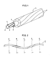
- Fig. 1 is a fragmentary perspective view showing an optical composite aerial ground wire 1 obtained by an embodiment of this invention.
- the optical composite aerial ground wire 1 shown therein has an optical fiber unit 2 serving as a central wire material.
- the optical fiber unit 2 has a circular pipe 3 of aluminum or its alloy, in which a plurality of optical fiber cores 4 are inserted.
- the optical fiber cores 4 are received in spirally extending grooves 6 formed on the peripheral surface of a spacer 5 of, e.g., aluminum.
- a spacer 5 of, e.g., aluminum.
- six profile strands 7 of substantially sectorial cross-section are stranded together.
- the profile strands 7 are formed of steel wires or aluminum-covered steel wires, and when their tensile strength is not less than 60 kg/mm 2 , the significance of this invention becomes remarkable.
- the profile strands 7 form a substantially cylindrical stranded wire layer on the outer peripheral surface of the optical fiber unit 2.
- Fig. 2 is a front view showing one of the profile strands 7 shown in Fig. 1.
- the profile strand 7 has been given spiral twist.
- the cross-sectional shape of this profile strand 7 taken at different positions is shown collectively in Fig. 3.
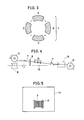
- Fig. 3 the sectorial cross-sections shown at A - D correspond to the cross-sections taken along the lines A - D of Fig. 2. As shown by arrows in Fig. 3, the cross-section changes as indicated at A, B, C, D, A and so on.
- profile strands 7 having the shape shown in Fig. 2 are prepared. This will be described below by successively referring to Figs. 4 and 5.
- Fig. 4 is a view for explaining the step of imparting twist to the profile strand 7.
- a conventional rigid type stranding machine which performs the so-called "non-untwisted" type stranding or twisting is shown.
- the profile strand 7 has been wound in the usual manner on a bobbin 8 on the supply side.
- the profile strand 7 drawn out of the bobbin 8 is first passed through an eyeplate 9, and via preform rollers 10, it is passed through a collector die 11 and wound on a bobbin 12 on the take-up side.
- the bobbin 8, eyeplate 9 and preform rollers 10 are synchronously rotated around the centerline 13.
- the twist pitch for the profile strand 7 to be wound on the bobbin 12 can be optionally selected by adjusting the length of the profile strand 7 to be wound per unit time on the bobbin 12 on the take-up side, and the number of revolutions per unit time around the centerline 13.
- another bobbin 8 on the supply side is shown in phantom lines in Fig. 4; this is for the purpose of making a clear distinction between this type of stranding and the "untwisted" type of stranding to be later described.
- the bobbin 8 makes one revolution around its own axis (own-axis revolution) while making one revolution around the centerline 13 (orbital revolution) as in the case of the relative motion between the earth and the moon.
- a "take-up rotary type stranding machine having no untwisting function" may be used in the place of the "rigid type stranding machine".
- the bobbin 8 on the supply side will not rotate around the centerline 13 and, reversely, the bobbin 12 on the take-up side will rotate around the centerline 13.
- the bobbin 12 having the twisted profile strand 7 wound thereon is then heat-treated in, e.g., a batch furnace 14.
- This heat treatment is performed to remove the residual stresses in the twisted profile strand 7 and has only to be effective in at least removing the strains in the material of the profile strand 7. If, however, this heat treatment condition is too severe, an excessive annealing effect would be produced on the material of the profile strand 7,-decreasing the strength to a great extent.
- a temperature condition of 200 - 500 °C is selected and about 30 minutes of heat treatment is effected. If the temperature is less than 200 °C, the strains in the profile strand 7 could not be removed, while, reversely, if it exceeds 500 °C, the strength of the profile strand 7 would be decreased.
- a heat-treating device 15 may be placed at a position shown in phantom lines in Fig. 4 so as to effect the heat treatment in the so-called in-line manner.
- the heat-treating furnace 15 used herein may be a high frequency induction heating device or a tunnel furnace.
- a high frequency induction heating device may be used in the batch type shown in Fig. 5.
- the Joule heat may be used as heating means by passing a current directly through the profile strand 7.
- a plurality of twisted and strain-removed profile strands 7 are used to form a stranded wire layer on the optical fiber unit 2 which serves as the central wire material.
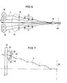
- This step is performed by e.g., a planetary type stranding machine which performs the "untwisted" type of stranding, and Fig. 6 shows an example in which the stranding is performed by a planetary type stranding machine.
- 6 bobbins 12 each having a twisted and strain-removed profile strand 7 wound thereon are prepared, said bobbins 12 being mounted on a bobbin orbital-rotation device (not shown).
- a bobbin orbital-rotation device not shown.
- the two bobbins 12 on the front side are omitted from the illustration, but all the bobbins have their axial directions maintained substantially fixed by the bobbin orbital-rotation device while executing planetary motion around the optical fiber unit 2. That is, the bobbins 12 only make orbital rotation without making own-axis rotation, just as the seats of a Ferris wheel are rotated with the rotation of the wheel. This is a feature of the "untwisted" type.
- the profile strands 7 withdrawn from the bobbins 12 are passed through the eyeplate 16 and while they are being guided by the preform rollers 17, they are collected in the collector die 18.
- the preform rollers 17 grouped in, e.g., 3 rollers, and the distance between the first and the third is selected so that it is equal to the twist or strand pitch of the stranded wire to be obtained.
- the eyeplate 16 and preform rollers 17 are rotated or caused to make orbital rotation (in the direction of arrow 19) while the optical fiber unit 2 which serves as the central wire material is fed in the direction of arrow 20.
- the device for feeding the optical fiber unit 2 though not shown, includes a capstan directed as indicated by arrow 20 and a take-up drum.
- the movements of the components included in the aforesaid motion system are relative, and the planetary type stranding machine may be replaced by a "take-up rotary type stranding machine having an untwisting function".
- the collector die 18, capstan and take-up drum (winder) are rotated in the direction of arrow 19 while the bobbins 12, eyeplate 16 and preform rollers 17 are not rotated in the direction of arrow 19 but are stationary, and the optical fiber unit 2 which serves as the central wire material is rotating in the direction of arrow 19.
- rotation is imparted to each bobbin 12 so that it rotates the profile strand 7 in a direction at right angles to the direction of withdrawal of the profile strand 7, i.e., around its axis.
- Fig. 7 shows a first example of means for restraining the inclined attitudes of the profile strands.
- a pair of rollers 21 and 22 are rotatably attached to the eyeplate 16 through a bracket 23.
- the peripheral surfaces of the rollers 21 and 22 are formed with a pair of grooves 24 and 25 having cross-sections which, when combined, correspond to the cross-section of the profile strand 7.
- the stranding site 26 must be positioned at a crest of the sine curve.
- the rollers 21 and 22 are also located at a crest of the sine curve. Therefore, the position where the rollers 21 and 22 are installed is such that the distance from the rollers 21 and 22 to the stranding site 26 is an integral multiple of the period of the sine curve.
- Fig. 7 shows one profile strand 7, but the same arrangement also applied to the other profile strands.
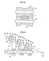
- Fig. 9 shows a second example of the means for restraining the inclined attitudes of profile strands.
- the illustrated arrangement is positioned at the place where the preform rollers 17 of Fig. 6 were located.
- three pairs of rollers 28 - 33 are installed and rotatably held by brackets 34 - 36.
- the brackets 34 - 36 are respectively fixed to turntables 37 - 39.
- the turntables 37 - 39 are respectively held by holder blocks 40 - 42 so that they are rotatable around an axis 43.
- the holder blocks 40 - 42 are fixed to a pipe 47 respectively through arms 44 - 46.
- the pipe 47 rotates integrally with the eyeplate 16 and allows the optical fiber unit 2 to pass through the interior thereof.
- the turntables 37 - 39 are attached so that they are rotatable around the axis 43. Therefore, the pairs of rollers 28 - 33 can be rotated in the direction of arrow 48 to change their directions. By tightening up screws 49 - 51, the inclinations of the rollers 28 - 33 are fixed.
- the shape of the rollers 28 - 33 is not specifically illustrated but they have grooves similar to those of the aforesaid rollers 21 and 22.
- Fig. 9 when the configuration of the profile strand 7 is regarded as a sine curve, the pairs of rollers 28 - 33 are shown located at positions corresponding to crests of the sine curve. In this example, however, even if the rollers are not positioned at crests, the inclined attitude of the profile strand 7 on its cross-section can be restrained.
- Fig. 10 shows a case where a profile strand 7a whose twist pitch differs is used.
- the positions where the rollers 28 - 33 are located may deviate from crests of the sine curve, as described above.
- the positions of the rollers 28 - 33 shown in Fig. 10 are all deviated from crests of the profile strand 7a.
- the aforesaid screws 49 - 51 are loosened and the rollers 28 - 33 are rotated round the axis 43 until desired inclinations are obtained, whereupon the screws 49 - 51 are tightened again to fix the inclinations.
- Such arrangement is advantageous in cases where it is necessary to produce stranded wires of different pitches by a single stranding machine.
- rollers 28 - 33 may be installed with their inclinations fixed. Further, the arrangement for adjusting the inclinations of the rollers is also applicable to the rollers 21 and 22 of Fig. 7 described above.
- Fig. 11 shows a third example of the means for restraining the inclination of the profile strand 7 on its cross-section.
- the same consideration as in the second example has been given.
- three pairs of rollers 52 - 57 are rotatably held by brackets 58 - 60.
- Attaching blocks 61 - 63 extend integrally from the brackets 58 - 63, respectively.
- an attaching plate 65 radially extends from the pipe 64 adapted to be rotated integrally with the eyeplate 16.
- the attaching plate 65 is formed with an elongated opening 66 extending parallel to the axis of the profile strand 7.
- a plurality of bolts 67 are prepared, said bolts extending through the attached blocks 61 - 63 and elongated opening 66 and threadedly engaged with nuts (not shown) on the back side of the attaching plate 65.
- the inclinations of the rollers 52 - 57 are fixed, but their positions along the length of the profile strand 7 are adjustable. That is, when the bolts 67 are loosened, the attaching blocks 61 - 63 are allowed to move along the elongated opening 66, and by tightening the bolts 67 again, the attaching blocks can be fixed in position. Therefore, the rollers 52 - 57 can be adjusted so that they are positioned at, e.g., crests of the profile strand 7.
- Figs. 9 and 11 the illustration has been shown in connection with only one profile strand, but the same arrangement is added for the other profile strands, as in the case of Fig. 7. That is, in the example shown in Fig. 9, six sets of arms 44 - 46 extend radially of the pipe 47, while in the example shown in Fig. 11, six attaching plates 65 radially extend around the pipe 64.
- the means for restraining the inclinations of the profile strands 7 on their cross-sections respectively described with reference to Figs. 7 - 11 may be provided in combination for a single stranding machine.
- Fig. 12 shows a modification of the rollers 21 and 22 shown in Fig. 7.
- the cross-sectional shape of the grooves 24 and 25 formed in the rollers 21 and 22 can be suitably changed.
- a profile strand 7 of sectorial cross-sectional shape is restrained in its vertical attitude.
- the grooves formed in the rollers 21 and 22 should be such that when combined, they define a cross-sectional corresponding to that of the profile strand 7.
- the means for restraining the inclined attitudes of the profile strands on their cross-sections need not be rollers in pairs.
- a die 68 shown in Figs. 13 and 14 may be used.
- Fig. 13 shows a front view of the die 68
- Fig. 14 shows a sectional view taken along the line IV - IV of Fig. 13.
- the die 68 is formed with a hole 69 corresponding in cross-section to the profile strand 7.
- Such die 68 may be used in the place of the rollers 21 - 22 in Fig. 7, the rollers 28 - 33 in Fig. 9 and the rollers 52 - 57 in Fig. 11
- Fig. 15 shows an arrangement desirable for use in embodying the method of this invention.
- the bobbins 12 have been shown as having their axes maintained in the same direction during planetary motion, but preferably the bobbin 12, as shown in Fig. 15, is constructed so that its inclination can be changed during planetary motion, as indicated by arrow 70.
- the rollers 21 and 22 of Fig. 7 are shown. If the inclined attitude of the profile strand 7 on its cross-section is to be restrained by such rollers 21 and 22, an excessive force can be produced in the twist direction on the profile strand 7 present between the bobbin 12 and the rollers 21, 22.
- the arrangement shown in Fig. 15 is so designed as to minimize such excessive force.
- a pair of rollers 71 and 72 are disposed between the bobbin 12 and the rollers 21, 22 and are adapted to be tilted in the directions indicated by arrow 73.
- the rollers 71 and 72 are formed with grooves 24 and 25 shown in Fig. 8 as in the case of the rollers 21 and 22.
- the angle of rotation of the rollers 71 and 72 in the directions of arrow 73 is also restrained through the profile strand 7 whose inclined attitude is restrained by the rollers 21 and 22. This angle of rotation is detected by a rotation angle detecting device 74, whose output is given to a rotation control device 75.
- the rotation control device 75 controls the bobbin 12 so that it assumes a desired inclination according to the angle of rotation of the rollers 71 and 72.
- profile strands to be used in this invention are not limited to those obtained through said process, and they may be obtained by the following process.
- the profile strand 7 may be subjected to the action of a plurality of rollers 76a - 76f.
- Such plurality of rollers 76a - 76f correspond to the aforesaid post-form rollers, but the post-form step in this case is applied only to the profile strand 7 and it is possible to impose a considerably severe condition, enabling sufficient removal of strains to be effected.
- a so-called “dummy" strand core 77 may be used to strand a plurality of profile strands 7 together around said core'by the "non-untwisted" type.
- the profile strands 7 are separated one by one as shown in Fig. 18 and they may be supplied from the bobbins 12 shown in Fig. 6.
- the cross-sectional shape of profile strands has been shown as a sector, but the invention is not limited thereto and can be advantageously applied provided that the strands are other than circular in cross-section.
Landscapes
- Physics & Mathematics (AREA)
- General Physics & Mathematics (AREA)
- Optics & Photonics (AREA)
- Engineering & Computer Science (AREA)
- Manufacturing & Machinery (AREA)
- Ropes Or Cables (AREA)
- Wire Processing (AREA)
- Processes Specially Adapted For Manufacturing Cables (AREA)
- Communication Cables (AREA)
Abstract
Description
- This invention relates to a method and apparatus for stranding profile strands. The products obtained by the method and apparatus of this invention typically include composite aerial wires such as aerial ground wires and aerial transmission wires, but they also include stranded wires such as ropes. In addition, this invention is advantageous particularly when applied to an optical composite aerial ground wire having an optical transmission function.
- For example, an aerial ground wire which has been used from of old is formed of an aluminum covered steel wire and/or aluminum alloy wire of circular cross section, and comprises a single wire and some, e.g., 6 strands twisted therearound. Recently, however, with the spread of optical transmission, an attempt has been made to make efficient use of an aerial ground wire by imparting an optical transmission function thereto.
- Such aerial ground wire having an optical transmission function uses an optical fiber unit as the central wire material. There are various types of optical fiber units, but most of them comprise a pipe of aluminum or its alloy which receives an optical fiber core. However, the tensile strength of an optical fiber unit is not so high as that of an ordinary wire. Thus, the use of an optical fiber unit results in a decrease in the strength of the aerial ground wire as a whole. To obtain the strength necessary for an aerial ground wire, it may be thought to increase the diameter of strands to be used. If, however, such procedure is simply put to practice, the apparent diameter of the aerial ground wire in its entirety increases and hence the wire is liable to receive an increased wind pressure; thus, from the standpoint of use of an aerial ground wire, the result is not so desirable.
- As a method of increasing the cross-sectional area and the strength of each strand while decreasing the outer diameter of the entire aerial ground wire, the following suggestion has been made: the cross-section of strands to be stranded or twisted together around an optical fiber unit should be made substantially a sector so that the outer surface of the aerial ground wire obtained is substantially a cylindrical peripheral surface. In addition, the sector referred to herein is a shape which is obtained when an area defined between two concentric circles is cut by radially extending lines. If a stranded wire is formed of strands each having such cross-sectional shape, not only is the tensile strength increased without increasing the outer diameter of the stranded wire so much, but also there is obtained a concomitant effect that the ambient pressure on the optical fiber unit passing through the center is relieved by the bridge effect of the strands forming the stranded wire layer.
- However, profile strands having a profile cross-section encounters some problems during stranding. The conventional stranding methods are roughly classified into two types; one is the so-called "untwisted" type, the stranding machines for this type of stranding including the "planetary type stranding machine", "tubular type stranding machine" and "take-up rotary type stranding machine having an untwisting function". The other type is the so-called "non-untwisting" type, the stranding machines for this type of stranding including the "rigid type stranding machine" and "take-up rotary type stranding machine having no untwisting function".
- In the "untwisted" type, e.g., in a planetary type stranding machine where the cage is rotated, bobbins for supplying strands are caused to perform planetary motion around the central wire material while maintaining their axes directed in a fixed direction. Therefore, the strands will be spirally wound around the central wire material while their inclined attitudes on the cross-sections of the strands to be stranded together around the central wire material are maintained constant. If the cross-section of the strands is circular, even the use of this type of stranding makes it possible to arrange the strands regularly around the outer peripheral surface of the central wire material, but in the case of profile strands having a profile cross-section such as a sector, this "untwisted" type cannot be simply used.
- In contrast thereto, with the "non-untwisted" type of stranding, said profile strands can be stranded together in a state in which they are in close surface contact with the outer peripheral surface of the central wire material. However, the strands stranded together by this type will have large stresses remaining therein, and unless these stresses are removed, it is impossible to obtain a stranded wire having satisfactory performance. That is, what are required of a stranded wire are freedom from the "loosening" of the strands, freedom from the rotation (untwisting) of the entire stranded wire, and freedom from the "undulation" of the stranded wire (which means that the stranded wire should be straight as a whole). However, where stranding is performed by the "non-untwisted" type, the aforesaid requirements for stranded wires cannot be met due to residual stresses in the strands. For this reason, where stranding is performed by the "non-untwisted" type, it has been usual practice to pass the stranded wire through a post-form step subsequent to the stranding or twisting step so as to remove the residual stresses in the strands. This post-form step is performed by post-form rollers externally pressing the stranded wire.
- Even if this post-form step is performed, this does not necessarily mean that all the problems caused by the "non-untwisted" type can be solved. First, in the case of a stranded wire of high tensile strength, such as is formed of steel strands, the residual stresses cannot be completely removed by a mere post-form step. Particularly in the case of a stranded wire with the aforesaid optical fiber unit used as the central wire material, the optical fiber unit can be damaged by this post-form step. That is, the pressure applied by the post-form step can deform the pipe which forms the outer periphery of the optical fiber unit, thus crushing the optical fiber unit in the interior, or the rollers used in the post-form step produce a tensile force which can break the optical fiber unit in the interior.
- According to the aforesaid "untwisted" type of stranding, the problem due to the residual stresses attendant on the "non-untwisted" type is at least eliminated. Thus, for stranding profile strands, it is preferable to use this "untwisted" type of stranding.
- Accordingly, an object of this invention is to provide a method of stranding profile strands together which is capable of performing the "untwisted" type of stranding.
- Another object of the invention is to provide an apparatus for stranding profile strands together which is capable of advantageously performing the aforesaid stranding method.
- The stranding method of this invention is a method of stranding a plurality of profile strands together around a central wire material. This method comprises the steps of imparting spiral twist to each profile strand, removing the strains of said twisted profile strands, and stranding said twisted strands together around a central wire material on the basis of the "untwisted" type. The spiral twist applied in advance to profile strands is connected with the configuration which each strand assumes after the strands have been stranded together.
- The "untwisted" type of stranding is performed by causing the profile strands to execute planetary motion relative to the central wire material around the latter. Such stranding can be performed by two methods, one in which the profile strands are caused to execute planetary motion around the central wire material without rotating the latter and the other in which the central wire material is rotated around its axis while the profile strands are rotated around their axes with the positions of the axes of the profile strands being substantially fixed. In performing the former method, the "planetary type stranding machine" is advantageously used, while the "take-up rotary type stranding machine having an untwisting function" is advantageously used in performing the latter method.
- The stranding apparatus of this invention comprises at least the following components: a device for producing profile strands which have been given spiral twist, a plurality of bobbins each holding thereon the twisted profile strand as wound thereon, central wire material feeding means for feeding a central wire material in the direction of its axis, an eyeplate through which the profile strands drawn out of the bobbins are passed, a collector die for collecting and stranding together the strands drawn out of the bobbins around the central wire material, means which, while causing the bobbins to execute planetary motion relative to the central wire material, provides relative rotation around the axis of the central wire material between a first group consisting of the bobbins and eyeplate and a second group consisting of the central wire material and collector die, and means for restraining the inclined attitudes of the profile strands on their cross-sections at least one place between the bobbins and the collector die. Particularly the last-mentioned component is noteworthy, ensuring that each profile strand is controlled at the stranding site so that it always assumes the proper inclined attitude.
- According to the method of this invention, even if the strands are profile ones, it is possible to perform stranding of the so-called "untwisted" type such as the planetary type and therefore there is no possibility of stresses remaining in the strands. Thus, all the required qualities for stranded wires, i.e., freedom from the "loosening" of the strands, freedom from rotation of the entire stranded wire and freedom from "undulation" of the stranded wire, can be attained. Preferably, the residual stresses in the twisted strands are removed before they are stranded together. Thus, since the step of removing the residual stresses in the strands after stranding together, is unnecessary, what is mechanically weak, such as an optical fiber unit, can be used as a central wire material without any problem. Therefore, the stranding method of this invention has wide uses.
- According to the stranding apparatus of this invention, profile strands can be efficiently stranded together. Particularly, the means for restraining the inclined attitudes of the profile strands on their cross-sections enables the inclined attitudes of the profile strands at the stranding site to be properly maintained all the time, and even if the pitch of the pre-twist becomes incorrect, the stranding together of the strands can be continued under good conditions.
- These objects and other objects, features, aspects and advantages of the present invention will become more apparent from the following detailed description of the present invention when taken in conjunction with the accompanying drawings.
-
- Fig. 1 is a fragmentary perspective view showing an optical composite
aerial ground wire 1 as an example of a stranded wire obtained by this invention; - Fig. 2 is a front view singly showing only one of the
profile strands 7 shown in Fig. 1; - Fig. 3 shows the cross-section of the
profile strand 7 taken at different positions shown in Fig. 2; - Fig. 4 diagrammatically shows the step of imparting spiral twist to the
profile strand 7; - Fig. 5 diagranunatically shows the step of heat-treating the
twisted profile strand 7; - Fig. 6 diagrammatically shows the step of stranding together the twisted and strain-removed profile strands;
- Fig. 7 shows a first example of means for restraining the inclined attitude of the
profile strand 7; - Fig. 8 is an enlarged sectional view taken along the line VII - VII of Fig. 7;
- Fig. 9 shows a second example of means for restraining the inclined attitude of the
profile strand 7; - Fig. 10 shows a manner in which rollers 28 - 33 in Fig. 9 are adjusted;
- Fig. 11 shows a third example of means for restraining the inclined attitude of the
profile strand 7; - Fig. 12 shows modifications of
rollers - Fig. 13 is a front view of a die 68 shown as another example of the inclined attitude restraining means;
- Fig. 14 is a sectional view taken along the line IV - IV of Fig. 13;
- Fig. 15 diagrammatically shows a mechanism for controlling the inclination of a
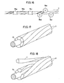
bobbin 12; - Fig. 16 diagrammatically shows another example of the step of removing strains in the
profile strand 7; and - Figs. 17 and 18 are views for explaining still another step of obtaining a spirally twisted and strain-removed
profile strand 7. - Embodiments of this invention will now be described in detail with reference to the accompanying drawings.
- Fig. 1 is a fragmentary perspective view showing an optical composite
aerial ground wire 1 obtained by an embodiment of this invention. The optical compositeaerial ground wire 1 shown therein has anoptical fiber unit 2 serving as a central wire material. Theoptical fiber unit 2 has acircular pipe 3 of aluminum or its alloy, in which a plurality ofoptical fiber cores 4 are inserted. Theoptical fiber cores 4 are received in spirally extendinggrooves 6 formed on the peripheral surface of aspacer 5 of, e.g., aluminum. On the outer surface of suchoptical fiber core 2, sixprofile strands 7 of substantially sectorial cross-section are stranded together. Theprofile strands 7 are formed of steel wires or aluminum-covered steel wires, and when their tensile strength is not less than 60 kg/mm2, the significance of this invention becomes remarkable. Theprofile strands 7 form a substantially cylindrical stranded wire layer on the outer peripheral surface of theoptical fiber unit 2. - Fig. 2 is a front view showing one of the
profile strands 7 shown in Fig. 1. Theprofile strand 7 has been given spiral twist. The cross-sectional shape of thisprofile strand 7 taken at different positions is shown collectively in Fig. 3. - In Fig. 3, the sectorial cross-sections shown at A - D correspond to the cross-sections taken along the lines A - D of Fig. 2. As shown by arrows in Fig. 3, the cross-section changes as indicated at A, B, C, D, A and so on. In performing the method of this invention, first,
profile strands 7 having the shape shown in Fig. 2 are prepared. This will be described below by successively referring to Figs. 4 and 5. - Fig. 4 is a view for explaining the step of imparting twist to the
profile strand 7. In Fig. 4, a conventional rigid type stranding machine which performs the so-called "non-untwisted" type stranding or twisting is shown. Theprofile strand 7 has been wound in the usual manner on abobbin 8 on the supply side. Theprofile strand 7 drawn out of thebobbin 8 is first passed through aneyeplate 9, and viapreform rollers 10, it is passed through a collector die 11 and wound on abobbin 12 on the take-up side. Thebobbin 8,eyeplate 9 and preformrollers 10 are synchronously rotated around thecenterline 13. Therefore, the twist pitch for theprofile strand 7 to be wound on thebobbin 12 can be optionally selected by adjusting the length of theprofile strand 7 to be wound per unit time on thebobbin 12 on the take-up side, and the number of revolutions per unit time around thecenterline 13. In addition, anotherbobbin 8 on the supply side is shown in phantom lines in Fig. 4; this is for the purpose of making a clear distinction between this type of stranding and the "untwisted" type of stranding to be later described. During withdrawal of theprofile strand 7, thebobbin 8 makes one revolution around its own axis (own-axis revolution) while making one revolution around the centerline 13 (orbital revolution) as in the case of the relative motion between the earth and the moon. - In addition, the movements of the components in the aforesaid motion system are relative, and a "take-up rotary type stranding machine having no untwisting function" may be used in the place of the "rigid type stranding machine". In this case, in Fig. 4, the
bobbin 8 on the supply side will not rotate around thecenterline 13 and, reversely, thebobbin 12 on the take-up side will rotate around thecenterline 13. - As shown in Fig. 5, the
bobbin 12 having thetwisted profile strand 7 wound thereon is then heat-treated in, e.g., abatch furnace 14. This heat treatment is performed to remove the residual stresses in thetwisted profile strand 7 and has only to be effective in at least removing the strains in the material of theprofile strand 7. If, however, this heat treatment condition is too severe, an excessive annealing effect would be produced on the material of theprofile strand 7,-decreasing the strength to a great extent. As for preferable conditions, in the case of theprofile strand 7 of aforesaid material, a temperature condition of 200 - 500 °C is selected and about 30 minutes of heat treatment is effected. If the temperature is less than 200 °C, the strains in theprofile strand 7 could not be removed, while, reversely, if it exceeds 500 °C, the strength of theprofile strand 7 would be decreased. - As for the heat-treating method, besides using the
batch furnace 14 shown in Fig. 5, a heat-treatingdevice 15 may be placed at a position shown in phantom lines in Fig. 4 so as to effect the heat treatment in the so-called in-line manner. The heat-treatingfurnace 15 used herein may be a high frequency induction heating device or a tunnel furnace. In addition, in the batch type shown in Fig. 5, a high frequency induction heating device may be used. Further, the Joule heat may be used as heating means by passing a current directly through theprofile strand 7. - Subsequently, as shown in Fig. 6, a plurality of twisted and strain-removed
profile strands 7 are used to form a stranded wire layer on theoptical fiber unit 2 which serves as the central wire material. This step is performed by e.g., a planetary type stranding machine which performs the "untwisted" type of stranding, and Fig. 6 shows an example in which the stranding is performed by a planetary type stranding machine. Thus, 6bobbins 12 each having a twisted and strain-removedprofile strand 7 wound thereon are prepared, saidbobbins 12 being mounted on a bobbin orbital-rotation device (not shown). In Fig. 6, the twobobbins 12 on the front side are omitted from the illustration, but all the bobbins have their axial directions maintained substantially fixed by the bobbin orbital-rotation device while executing planetary motion around theoptical fiber unit 2. That is, thebobbins 12 only make orbital rotation without making own-axis rotation, just as the seats of a Ferris wheel are rotated with the rotation of the wheel. This is a feature of the "untwisted" type. Theprofile strands 7 withdrawn from thebobbins 12 are passed through theeyeplate 16 and while they are being guided by thepreform rollers 17, they are collected in the collector die 18. Thepreform rollers 17 grouped in, e.g., 3 rollers, and the distance between the first and the third is selected so that it is equal to the twist or strand pitch of the stranded wire to be obtained. - In synchronism with the planetary motion of the
bobbins 12, theeyeplate 16 andpreform rollers 17 are rotated or caused to make orbital rotation (in the direction of arrow 19) while theoptical fiber unit 2 which serves as the central wire material is fed in the direction ofarrow 20. In addition, the device for feeding theoptical fiber unit 2, though not shown, includes a capstan directed as indicated byarrow 20 and a take-up drum. - In addition, the movements of the components included in the aforesaid motion system are relative, and the planetary type stranding machine may be replaced by a "take-up rotary type stranding machine having an untwisting function". In this case, the collector die 18, capstan and take-up drum (winder) are rotated in the direction of
arrow 19 while thebobbins 12,eyeplate 16 andpreform rollers 17 are not rotated in the direction ofarrow 19 but are stationary, and theoptical fiber unit 2 which serves as the central wire material is rotating in the direction ofarrow 19. Further, to provide the untwisting function, rotation is imparted to eachbobbin 12 so that it rotates theprofile strand 7 in a direction at right angles to the direction of withdrawal of theprofile strand 7, i.e., around its axis. - When rotation in the direction of
arrow 19 is imparted to eachprofile strand 7 while theoptical fiber unit 2 is being fed in the direction ofarrow 20, as described above, at the position of the collector die 18 theprofile strands 7 are stranded together; thus, the desired wire stranding is performed. - When the aforesaid wire stranding step is being performed for a long time (i.e., over a long distance), the error between the twist pitch of the
profile strands 7 and the twist or strand pitch of the stranded wire builds up, so that the inclined attitudes of the profile strands on their cross-sections at the stranding site sometimes go out of the desired condition. Thus, it is preferable to take measures against this phenomenon. This is achieved by providing means for restraining the inclined attitudes of theprofile strands 7 on their cross-sections at at least one place between thebobbin 12 and the collector die 18. Some examples of such means will be described below. - Fig. 7 shows a first example of means for restraining the inclined attitudes of the profile strands. In Fig. 7, a pair of
rollers eyeplate 16 through abracket 23. As is clear from Fig. 8 showing an enlarged cross-section taken along the line VII - VII of Fig. 7, the peripheral surfaces of therollers grooves profile strand 7. Thus, when theprofile strand 7 passes through theserollers twisted profile strand 7 is modeled on a sine curve, thestranding site 26 must be positioned at a crest of the sine curve. In the illustrated example, therollers rollers rollers stranding site 26 is an integral multiple of the period of the sine curve. In addition, Fig. 7 shows oneprofile strand 7, but the same arrangement also applied to the other profile strands. - Fig. 9 shows a second example of the means for restraining the inclined attitudes of profile strands. The illustrated arrangement is positioned at the place where the
preform rollers 17 of Fig. 6 were located. In this example, three pairs of rollers 28 - 33 are installed and rotatably held by brackets 34 - 36. The brackets 34 - 36 are respectively fixed to turntables 37 - 39. The turntables 37 - 39 are respectively held by holder blocks 40 - 42 so that they are rotatable around anaxis 43. The holder blocks 40 - 42 are fixed to apipe 47 respectively through arms 44 - 46. Thepipe 47 rotates integrally with theeyeplate 16 and allows theoptical fiber unit 2 to pass through the interior thereof. - As described above, the turntables 37 - 39 are attached so that they are rotatable around the
axis 43. Therefore, the pairs of rollers 28 - 33 can be rotated in the direction ofarrow 48 to change their directions. By tightening up screws 49 - 51, the inclinations of the rollers 28 - 33 are fixed. In addition, the shape of the rollers 28 - 33 is not specifically illustrated but they have grooves similar to those of theaforesaid rollers - In Fig. 9, when the configuration of the
profile strand 7 is regarded as a sine curve, the pairs of rollers 28 - 33 are shown located at positions corresponding to crests of the sine curve. In this example, however, even if the rollers are not positioned at crests, the inclined attitude of theprofile strand 7 on its cross-section can be restrained. - Fig. 10 shows a case where a
profile strand 7a whose twist pitch differs is used. In this case, the positions where the rollers 28 - 33 are located may deviate from crests of the sine curve, as described above. The positions of the rollers 28 - 33 shown in Fig. 10 are all deviated from crests of theprofile strand 7a. In this case, the aforesaid screws 49 - 51 are loosened and the rollers 28 - 33 are rotated round theaxis 43 until desired inclinations are obtained, whereupon the screws 49 - 51 are tightened again to fix the inclinations. Such arrangement is advantageous in cases where it is necessary to produce stranded wires of different pitches by a single stranding machine. - If such advantage is not desired, the rollers 28 - 33 may be installed with their inclinations fixed. Further, the arrangement for adjusting the inclinations of the rollers is also applicable to the
rollers - Fig. 11 shows a third example of the means for restraining the inclination of the
profile strand 7 on its cross-section. In this example, too, the same consideration as in the second example has been given. First, as in the second example, three pairs of rollers 52 - 57 are rotatably held by brackets 58 - 60. Attaching blocks 61 - 63 extend integrally from the brackets 58 - 63, respectively. On the other hand, an attachingplate 65 radially extends from thepipe 64 adapted to be rotated integrally with theeyeplate 16. The attachingplate 65 is formed with anelongated opening 66 extending parallel to the axis of theprofile strand 7. To attach the rollers 52 - 57 to the attachingplate 65, a plurality ofbolts 67 are prepared, said bolts extending through the attached blocks 61 - 63 andelongated opening 66 and threadedly engaged with nuts (not shown) on the back side of the attachingplate 65. - In the example shown in Fig. 11, the inclinations of the rollers 52 - 57 are fixed, but their positions along the length of the
profile strand 7 are adjustable. That is, when thebolts 67 are loosened, the attaching blocks 61 - 63 are allowed to move along theelongated opening 66, and by tightening thebolts 67 again, the attaching blocks can be fixed in position. Therefore, the rollers 52 - 57 can be adjusted so that they are positioned at, e.g., crests of theprofile strand 7. - In Figs. 9 and 11, the illustration has been shown in connection with only one profile strand, but the same arrangement is added for the other profile strands, as in the case of Fig. 7. That is, in the example shown in Fig. 9, six sets of arms 44 - 46 extend radially of the
pipe 47, while in the example shown in Fig. 11, six attachingplates 65 radially extend around thepipe 64. - The means for restraining the inclinations of the
profile strands 7 on their cross-sections respectively described with reference to Figs. 7 - 11 may be provided in combination for a single stranding machine. - Fig. 12 shows a modification of the
rollers grooves rollers profile strand 7 of sectorial cross-sectional shape is restrained in its vertical attitude. In short, the grooves formed in therollers profile strand 7. - In addition, the modification shown in Fig. 12 is likewise applicable to the rollers 28 - 33 shown in Fig. 9 and to the rollers 52 - 57 shown in Fig. 11.
- The means for restraining the inclined attitudes of the profile strands on their cross-sections need not be rollers in pairs. For example, a die 68 shown in Figs. 13 and 14 may be used. Fig. 13 shows a front view of the
die 68 and Fig. 14 shows a sectional view taken along the line IV - IV of Fig. 13. Thedie 68 is formed with ahole 69 corresponding in cross-section to theprofile strand 7. Such die 68 may be used in the place of the rollers 21 - 22 in Fig. 7, the rollers 28 - 33 in Fig. 9 and the rollers 52 - 57 in Fig. 11 - Fig. 15 shows an arrangement desirable for use in embodying the method of this invention. In Fig. 6, the
bobbins 12 have been shown as having their axes maintained in the same direction during planetary motion, but preferably thebobbin 12, as shown in Fig. 15, is constructed so that its inclination can be changed during planetary motion, as indicated byarrow 70. In Fig. 15, therollers profile strand 7 on its cross-section is to be restrained bysuch rollers profile strand 7 present between thebobbin 12 and therollers rollers bobbin 12 and therollers arrow 73. Therollers grooves rollers rollers arrow 73 is also restrained through theprofile strand 7 whose inclined attitude is restrained by therollers angle detecting device 74, whose output is given to arotation control device 75. Therotation control device 75 controls thebobbin 12 so that it assumes a desired inclination according to the angle of rotation of therollers bobbin 12 is controlled so that therollers rollers profile strand 7 between thebobbin 12 and therollers - The results of experiments conducted to ascertain the effect of this invention will now be described. First, as the most preferable example which is within the scope of this invention, after twist was imparted to profile strands, the latter were heat-treated at 320 °C to remove their strains, whereupon they were stranded together by a planetary type stranding machine while performing the restraint shown in Fig. 9, whereby a very good strand or twist condition was obtained over a long distance.
- In contrast thereto, when said profile strands were stranded together without performing the restraint shown in Fig. 9, a good strand or twist condition was maintained over 500 m.
- However, when profile strands each of which was twisted but was not heat-treated for removal of the strains were used, it was found that even if the restraint shown in Fig. 9 was given to the profile strands, the resulting stranded wire had poor performance, having an increased tendency of rotation of the entire stranded wire. ―-Further, when profile strands were stranded together by the "non-untwisted" type, the resulting stranded wire had an increased tendency of rotation of the entire stranded wire and its performance was worse.
- In addition, profile strands to be used in this invention are not limited to those obtained through said process, and they may be obtained by the following process.
- In the embodiments described above, heat treatment has been performed to remove the strains in the profile strands having spiral twist given thereto, but as shown in Fig. 16 the
profile strand 7 may be subjected to the action of a plurality ofrollers 76a - 76f. Such plurality ofrollers 76a - 76f correspond to the aforesaid post-form rollers, but the post-form step in this case is applied only to theprofile strand 7 and it is possible to impose a considerably severe condition, enabling sufficient removal of strains to be effected. - As shown in Fig. 17, a so-called "dummy"
strand core 77 may be used to strand a plurality ofprofile strands 7 together around said core'by the "non-untwisted" type. After the strains in theprofile strand 7 are removed by heat treatment or by using the rollers shown in Fig. 16, theprofile strands 7 are separated one by one as shown in Fig. 18 and they may be supplied from thebobbins 12 shown in Fig. 6. - So far, the invention has been described in detail on the basis of embodiments thereof illustrated with respect to the case of obtaining optical composite aerial ground wires, but the invention is likewise applicable to transmission lines and to ropes.
- In the illustrated embodiments, the cross-sectional shape of profile strands has been shown as a sector, but the invention is not limited thereto and can be advantageously applied provided that the strands are other than circular in cross-section.
- Although the present invention has been described and illustrated in detail, it is clearly understood that the same is by way of illustration and example only and is not to be taken by way of limitation, the scope of the present invention being limited only by the terms of the appended claims.
Claims (30)
Applications Claiming Priority (2)
| Application Number | Priority Date | Filing Date | Title |
|---|---|---|---|
| JP58248942A JPS60137536A (en) | 1983-12-26 | 1983-12-26 | Method and device for twisting irregularly shaped wires |
| JP248942/83 | 1983-12-26 |
Publications (3)
| Publication Number | Publication Date |
|---|---|
| EP0148447A2 true EP0148447A2 (en) | 1985-07-17 |
| EP0148447A3 EP0148447A3 (en) | 1987-05-13 |
| EP0148447B1 EP0148447B1 (en) | 1990-10-17 |
Family
ID=17185706
Family Applications (1)
| Application Number | Title | Priority Date | Filing Date |
|---|---|---|---|
| EP84115291A Expired EP0148447B1 (en) | 1983-12-26 | 1984-12-12 | Method and apparatus for stranding profile strands |
Country Status (4)
| Country | Link |
|---|---|
| US (1) | US4604861A (en) |
| EP (1) | EP0148447B1 (en) |
| JP (1) | JPS60137536A (en) |
| DE (1) | DE3483423D1 (en) |
Cited By (6)
| Publication number | Priority date | Publication date | Assignee | Title |
|---|---|---|---|---|
| EP0149824A3 (en) * | 1984-01-23 | 1987-05-13 | Sumitomo Electric Industries Limited | Method for stranding profile strand |
| EP0224598A4 (en) * | 1985-06-14 | 1988-10-06 | Ocean Cable Co Ltd | Pressure-tight layer in submarine optical cable and method of manufacturing same. |
| WO2007122597A2 (en) | 2006-04-26 | 2007-11-01 | The Procter & Gamble Company | Amide surfactant thickening systems for hair colouring and bleaching compositions |
| WO2015075536A1 (en) * | 2013-11-22 | 2015-05-28 | Toyota Jidosha Kabushiki Kaisha | Method of manufacturing assembled conductor and electric motor |
| EP3096440A1 (en) * | 2015-05-18 | 2016-11-23 | Toyota Jidosha Kabushiki Kaisha | Manufacturing method of coated conducting wire assembly |
| CN115573183A (en) * | 2022-10-20 | 2023-01-06 | 苏州越阔金属制品有限公司 | Medical unstressed steel wire rope and manufacturing method thereof |
Families Citing this family (14)
| Publication number | Priority date | Publication date | Assignee | Title |
|---|---|---|---|---|
| US5375404A (en) * | 1993-03-10 | 1994-12-27 | The University Of Akron | Wide rope with reduced internal contact stresses |
| DE4314172C1 (en) * | 1993-04-29 | 1994-09-15 | Witels App Masch Albert Gmbh | Preform head for ropes and cable reinforcements |
| US5661966A (en) * | 1996-06-27 | 1997-09-02 | Tokyo Rope Manufacturing Co. Ltd. | Steel cord for reinforcement of off-road tire, method of manufacturing the same, and off-road tire |
| KR100680159B1 (en) * | 1998-12-24 | 2007-02-08 | 피렐리 타이어 소시에떼 퍼 아찌오니 | Method and apparatus for manufacturing metal cord for reinforced elastomer products, especially tires |
| DE10261538A1 (en) * | 2002-12-23 | 2004-07-01 | Thyssenkrupp Presta Ag | steering column |
| CN101473088B (en) * | 2006-05-10 | 2012-12-05 | 倍耐力轮胎股份公司 | Metal cord and method for producing the same |
| FR2934348B1 (en) * | 2008-07-28 | 2010-08-20 | Technip France | METHOD AND INSTALLATION FOR CONSTRUCTING A LAYER OF ARMOR YARN |
| US10190256B2 (en) * | 2012-07-02 | 2019-01-29 | Casar Drahtseilwerk Saar Gmbh | Device and method for producing a strand or a cable |
| US9303355B2 (en) * | 2012-09-07 | 2016-04-05 | Bartell Machinery Systems, L.L.C. | Mode shift apparatus for umbilical stranding machine |
| CN103306150B (en) * | 2013-06-07 | 2016-01-20 | 南京诺尔泰复合材料设备制造有限公司 | The high strength composite twisted wire of trapezoid cross section and one-step preppn process thereof |
| DE102014005242B3 (en) * | 2014-04-08 | 2015-07-09 | SLE quality engineering GmbH & Co. KG | Method and device for determining an angular position of individual lines at a predetermined cross-sectional location in a multi-core sheathed cable |
| CN104384405A (en) * | 2014-09-17 | 2015-03-04 | 明光市锐创电气有限公司 | Forming process of electric wire fixing preformed armor rods |
| EP3303687B1 (en) * | 2015-05-26 | 2022-07-20 | Compagnie Générale des Etablissements Michelin | Unit for producing an assembly |
| JP7846513B2 (en) * | 2021-10-27 | 2026-04-15 | 朝日インテック株式会社 | wire rope |
Family Cites Families (14)
| Publication number | Priority date | Publication date | Assignee | Title |
|---|---|---|---|---|
| US1712264A (en) * | 1923-02-26 | 1929-05-07 | John R Gammeter | Machine and method for forming cables |
| BE346951A (en) * | 1926-12-13 | |||
| BE379534A (en) * | 1930-05-21 | 1931-06-30 | ||
| BE513964A (en) * | 1951-10-29 | |||
| US3231665A (en) * | 1962-09-18 | 1966-01-25 | United States Steel Corp | Stress-relieved stranded wire structure and method of making the same |
| US3142145A (en) * | 1963-01-28 | 1964-07-28 | Schlumberger Well Surv Corp | Method and apparatus for forming cables |
| US3188791A (en) * | 1963-04-22 | 1965-06-15 | United States Steel Corp | Locked coil cable and method of making same |
| DE2211111C3 (en) * | 1972-03-08 | 1978-10-19 | Fried. Krupp Gmbh, 4300 Essen | Method and device for machine stranding of elongated electrical individual conductors with non-circular cross-sections to form a cable |
| GB1424672A (en) * | 1972-04-25 | 1976-02-11 | Gkn Somerset Wire Ltd | Wire strand |
| US4009561A (en) * | 1975-06-02 | 1977-03-01 | Camesa, S.A. | Method of forming cables |
| DE2618586C3 (en) * | 1976-04-28 | 1981-11-12 | W.H. Küster GmbH & Co KG, 6332 Ehringshausen | Preforming device for stranding machines |
| JPS57121684A (en) * | 1980-12-27 | 1982-07-29 | Shinko Wire Co Ltd | Method and apparatus for producing wire rope with filler |
| IT1152225B (en) * | 1982-05-31 | 1986-12-31 | Pirelli Cavi Spa | APPARATUS FOR THE MANUFACTURE OF A CABLE WITH OPTICAL FIBERS |
| CH658480A5 (en) * | 1982-09-14 | 1986-11-14 | Fatzer Ag | METHOD AND DEVICE FOR PRODUCING WIRE STRANDS OR WIRE ROPES. |
-
1983
- 1983-12-26 JP JP58248942A patent/JPS60137536A/en active Granted
-
1984
- 1984-12-12 EP EP84115291A patent/EP0148447B1/en not_active Expired
- 1984-12-12 DE DE8484115291T patent/DE3483423D1/en not_active Expired - Lifetime
- 1984-12-17 US US06/682,652 patent/US4604861A/en not_active Expired - Lifetime
Cited By (10)
| Publication number | Priority date | Publication date | Assignee | Title |
|---|---|---|---|---|
| EP0149824A3 (en) * | 1984-01-23 | 1987-05-13 | Sumitomo Electric Industries Limited | Method for stranding profile strand |
| EP0224598A4 (en) * | 1985-06-14 | 1988-10-06 | Ocean Cable Co Ltd | Pressure-tight layer in submarine optical cable and method of manufacturing same. |
| US4867528A (en) * | 1985-06-14 | 1989-09-19 | Ocean Cable Co., Ltd. | Pressure-resistant sheath of a submarine optical fibre cable and method for the production thereof |
| WO2007122597A2 (en) | 2006-04-26 | 2007-11-01 | The Procter & Gamble Company | Amide surfactant thickening systems for hair colouring and bleaching compositions |
| WO2015075536A1 (en) * | 2013-11-22 | 2015-05-28 | Toyota Jidosha Kabushiki Kaisha | Method of manufacturing assembled conductor and electric motor |
| CN105849825A (en) * | 2013-11-22 | 2016-08-10 | 丰田自动车株式会社 | Method of manufacturing assembled conductor and electric motor |
| CN105849825B (en) * | 2013-11-22 | 2017-07-25 | 丰田自动车株式会社 | Manufacture the method and motor of combined conductor |
| EP3096440A1 (en) * | 2015-05-18 | 2016-11-23 | Toyota Jidosha Kabushiki Kaisha | Manufacturing method of coated conducting wire assembly |
| US10163551B2 (en) | 2015-05-18 | 2018-12-25 | Toyota Jidosha Kabushiki Kaisha | Methods of manufacturing a coated conducting wire assembly |
| CN115573183A (en) * | 2022-10-20 | 2023-01-06 | 苏州越阔金属制品有限公司 | Medical unstressed steel wire rope and manufacturing method thereof |
Also Published As
| Publication number | Publication date |
|---|---|
| EP0148447B1 (en) | 1990-10-17 |
| JPH0353058B2 (en) | 1991-08-13 |
| JPS60137536A (en) | 1985-07-22 |
| DE3483423D1 (en) | 1990-11-22 |
| US4604861A (en) | 1986-08-12 |
| EP0148447A3 (en) | 1987-05-13 |
Similar Documents
| Publication | Publication Date | Title |
|---|---|---|
| EP0148447B1 (en) | Method and apparatus for stranding profile strands | |
| EP0138731B1 (en) | Metallic cable | |
| EP0175633B1 (en) | Metallic cable and a method and apparatus for manufacturing the same | |
| EP0149824A2 (en) | Method for stranding profile strand | |
| CN110373922A (en) | A kind of production equipment and production method of steel cord | |
| EP0143732B1 (en) | Apparatus and process of manufacturing a metal cord | |
| US4195469A (en) | Method and device for producing metallic cords | |
| US2941348A (en) | Manufacture of wire strands, bunches, and cables | |
| JPH0221340B2 (en) | ||
| US4802328A (en) | Method of manufacturing wire ropes and wire rope twisting machine for effecting the same | |
| US4498281A (en) | Apparatus and method of making metallic cord | |
| KR100270170B1 (en) | Process for preparing steel cord and the apparatus for the same | |
| CA1146026A (en) | Stranding stock of large cross sections | |
| JPH0696832B2 (en) | Stranding method for deformed wires | |
| JPS60154830A (en) | Stranding method of deformed wire rod | |
| JPS60154829A (en) | How to twist irregularly shaped wires | |
| EP0094335B1 (en) | Apparatus and method of making metallic cord | |
| JPH07166485A (en) | Production of metal cord and apparatus therefor | |
| KR0182319B1 (en) | Metal cord manufacturing equipment | |
| JPH01156585A (en) | Preformed siding wire stranding machine | |
| JP2631462B2 (en) | Preform device for strands for deformed steel strands | |
| JPS60154828A (en) | Stranding method of deformed wire rod | |
| SU859516A1 (en) | Method of manufacturing shapely spun rope | |
| EP0801167A2 (en) | Machine for the single-twist stranding of cables composed of a plurality of wires, particularly for large-diameter cables | |
| WO1996015311A1 (en) | Manufacture of a reversed lay stranded assembly |
Legal Events
| Date | Code | Title | Description |
|---|---|---|---|
| PUAI | Public reference made under article 153(3) epc to a published international application that has entered the european phase |
Free format text: ORIGINAL CODE: 0009012 |
|
| AK | Designated contracting states |
Designated state(s): DE FR GB IT |
|
| PUAL | Search report despatched |
Free format text: ORIGINAL CODE: 0009013 |
|
| AK | Designated contracting states |
Kind code of ref document: A3 Designated state(s): DE FR GB IT |
|
| 17P | Request for examination filed |
Effective date: 19870923 |
|
| 17Q | First examination report despatched |
Effective date: 19880927 |
|
| RAP1 | Party data changed (applicant data changed or rights of an application transferred) |
Owner name: SUMITOMO ELECTRIC INDUSTRIES, LTD. |
|
| GRAA | (expected) grant |
Free format text: ORIGINAL CODE: 0009210 |
|
| ITF | It: translation for a ep patent filed | ||
| AK | Designated contracting states |
Kind code of ref document: B1 Designated state(s): DE FR GB IT |
|
| REF | Corresponds to: |
Ref document number: 3483423 Country of ref document: DE Date of ref document: 19901122 |
|
| ITTA | It: last paid annual fee | ||
| ET | Fr: translation filed | ||
| PLBE | No opposition filed within time limit |
Free format text: ORIGINAL CODE: 0009261 |
|
| STAA | Information on the status of an ep patent application or granted ep patent |
Free format text: STATUS: NO OPPOSITION FILED WITHIN TIME LIMIT |
|
| 26N | No opposition filed | ||
| PGFP | Annual fee paid to national office [announced via postgrant information from national office to epo] |
Ref country code: GB Payment date: 19991208 Year of fee payment: 16 Ref country code: FR Payment date: 19991208 Year of fee payment: 16 |
|
| PGFP | Annual fee paid to national office [announced via postgrant information from national office to epo] |
Ref country code: DE Payment date: 19991210 Year of fee payment: 16 |
|
| PG25 | Lapsed in a contracting state [announced via postgrant information from national office to epo] |
Ref country code: GB Free format text: LAPSE BECAUSE OF NON-PAYMENT OF DUE FEES Effective date: 20001212 |
|
| GBPC | Gb: european patent ceased through non-payment of renewal fee |
Effective date: 20001212 |
|
| PG25 | Lapsed in a contracting state [announced via postgrant information from national office to epo] |
Ref country code: FR Free format text: LAPSE BECAUSE OF NON-PAYMENT OF DUE FEES Effective date: 20010831 |
|
| REG | Reference to a national code |
Ref country code: FR Ref legal event code: ST |
|
| PG25 | Lapsed in a contracting state [announced via postgrant information from national office to epo] |
Ref country code: DE Free format text: LAPSE BECAUSE OF NON-PAYMENT OF DUE FEES Effective date: 20011002 |