EP0148394B2 - Enclosed switchgears - Google Patents
Enclosed switchgears Download PDFInfo
- Publication number
- EP0148394B2 EP0148394B2 EP84114421A EP84114421A EP0148394B2 EP 0148394 B2 EP0148394 B2 EP 0148394B2 EP 84114421 A EP84114421 A EP 84114421A EP 84114421 A EP84114421 A EP 84114421A EP 0148394 B2 EP0148394 B2 EP 0148394B2
- Authority
- EP
- European Patent Office
- Prior art keywords
- cable
- bushing
- cubicles
- conductor
- connectors
- Prior art date
- Legal status (The legal status is an assumption and is not a legal conclusion. Google has not performed a legal analysis and makes no representation as to the accuracy of the status listed.)
- Expired - Lifetime
Links
- 239000004020 conductor Substances 0.000 claims description 34
- 230000001681 protective effect Effects 0.000 claims description 8
- 239000011810 insulating material Substances 0.000 claims 1
- 229910018503 SF6 Inorganic materials 0.000 description 12
- WRQGPGZATPOHHX-UHFFFAOYSA-N ethyl 2-oxohexanoate Chemical compound CCCCC(=O)C(=O)OCC WRQGPGZATPOHHX-UHFFFAOYSA-N 0.000 description 7
- SFZCNBIFKDRMGX-UHFFFAOYSA-N sulfur hexafluoride Chemical compound FS(F)(F)(F)(F)F SFZCNBIFKDRMGX-UHFFFAOYSA-N 0.000 description 5
- 229960000909 sulfur hexafluoride Drugs 0.000 description 5
- 238000010586 diagram Methods 0.000 description 4
- 238000010276 construction Methods 0.000 description 2
- 238000007599 discharging Methods 0.000 description 2
- 239000004519 grease Substances 0.000 description 2
- 238000009434 installation Methods 0.000 description 2
- 239000004698 Polyethylene Substances 0.000 description 1
- 238000005452 bending Methods 0.000 description 1
- DMFGNRRURHSENX-UHFFFAOYSA-N beryllium copper Chemical compound [Be].[Cu] DMFGNRRURHSENX-UHFFFAOYSA-N 0.000 description 1
- 239000003822 epoxy resin Substances 0.000 description 1
- 238000009413 insulation Methods 0.000 description 1
- 230000013011 mating Effects 0.000 description 1
- 238000000034 method Methods 0.000 description 1
- 229920000647 polyepoxide Polymers 0.000 description 1
- -1 polyethylene Polymers 0.000 description 1
- 229920000573 polyethylene Polymers 0.000 description 1
- 239000012858 resilient material Substances 0.000 description 1
- XLYOFNOQVPJJNP-UHFFFAOYSA-N water Substances O XLYOFNOQVPJJNP-UHFFFAOYSA-N 0.000 description 1
Images

Classifications
-
- H—ELECTRICITY
- H02—GENERATION; CONVERSION OR DISTRIBUTION OF ELECTRIC POWER
- H02B—BOARDS, SUBSTATIONS OR SWITCHING ARRANGEMENTS FOR THE SUPPLY OR DISTRIBUTION OF ELECTRIC POWER
- H02B13/00—Arrangement of switchgear in which switches are enclosed in, or structurally associated with, a casing, e.g. cubicle
- H02B13/005—Electrical connection between switchgear cells
-
- H—ELECTRICITY
- H01—ELECTRIC ELEMENTS
- H01R—ELECTRICALLY-CONDUCTIVE CONNECTIONS; STRUCTURAL ASSOCIATIONS OF A PLURALITY OF MUTUALLY-INSULATED ELECTRICAL CONNECTING ELEMENTS; COUPLING DEVICES; CURRENT COLLECTORS
- H01R13/00—Details of coupling devices of the kinds covered by groups H01R12/70 or H01R24/00 - H01R33/00
- H01R13/46—Bases; Cases
- H01R13/53—Bases or cases for heavy duty; Bases or cases for high voltage with means for preventing corona or arcing
Definitions
- This invention relates to an enclosed type switchgear array comprising a plurality of gas-filled switch- gears or cubicles.
- Fig. 1 illustrates an example of such a cubicle generally designated by 11.
- the cubicle 11 comprises a box-shaped housing 12, the internal space thereof being separated by a vertical wall 13A and two horizontal walls 13B and 13C into three separate chambers 14A, 14B and 14C, all of which are filled with the sulfur hexafluoride (SF 6 ) gas.
- SF 6 sulfur hexafluoride
- Power source side buses 15 are provided to extend horizontally through an upper portion in the chamber 14A.
- Conductors 16 are provided to connect the buses 15 to a disconnect switch 17A provided in the chamber 14A, and then through an insulating plate 18A fitted in the separating wait 13Ato a circuit breaker 19 encased in the chamber 14B.
- a cable head 20 used for an out-going cable 21.
- Conductors 22 connect the terminals of the head conductors to another disconnect switch 17B, and then via an insulating plate 18B to lower poles (not shown) of the circuit breaker 19.
- sulfur hexafluoride (SF 6 ) gas is filled in the component cubicles, with the density, pressure and the water content of the gas being controlled to their standard ranges.
- the switchgear array thus assembled and filled with the insulating gas SF 6 is then disassembled into individual cubicles for the purpose of transportation.
- the buses 15 in the cubicles which are temporarily connected together are disconnected from each other, and reconnected in the site where the switchgear array is assembled together.
- two cubicles 11 and 11A which include buses 15 and 15A, are arranged in a spaced apart relation as shown in Fig. 2, with the ends of the buses 15 and 15A projecting outwardly from insulating plates 22 and 22A provided in the side walls of the cubicles 11 and 15, respectively.
- the outer ends of the buses 15 and 15A opposing each other are then connected together through conductors 23.
- a cylindrical cover 24 is secured, at both ends thereof, to the side walls of the cubicles 11 and 11A for encasing the connected portion of the buses 15 and 15A in a gas-tight manner, and sulfur hexafluoride gas (SF 6 ) is filled in the cylindrical cover 24.
- SF 6 sulfur hexafluoride gas
- the enclosed type switchgear array can be separated into the individual cubicles without opening any of the gas filled chambers 14A, 14B and 14C.
- the gas-filled cylindrical cover 24 must be opened each time when the buses 15 and 15A of the two adjacent cubicles 11 and 11 A are separated from each other, the SF 6 gas must be refilled inside of the cylindrical cover 24 after assembling the switchgear array in the installation site.
- FR-A-2 423 897 discloses an enclosed type switch gear array composed of a plurality of cubicles filled with sulfur hexafluoride (SF s ), each cubicle including electric apparatus and power source buses, the buses of adjoining cubicles being connected together through connectors provided outside of the cubicles and an insulated conductor cable extending between adjoining connectors. With this array it is not possible to connect or disconnect the buses included in the component cubicles without opening and closing any of the gas-filled chambers.
- SF s sulfur hexafluoride
- US-A-3 509 518 discloses a T-shaped cable connector for connecting two long cables end-to-end within a lateral tube of the connector and for connecting the long cables to a branch cable.
- This connector comprises a bushing, a conductor, a shielding element, an electrically conductive plug member, a resilient contacting piece, a stress cone and forcing means. But this cable connector is not usable for the purpose of electrical connection of cubicles according to the present invention.
- An object of this invention is to provide an enclosed type switchgear array wherein buses included in the component cubicles can be connected or disconnected without opening and closing any of the gas-filled chambers.
- Another object of this invention is to provide an enclosed type switchgear array wherein the connection of buses included in two adjacent cubicles can be realized by connectors provided outside of the cubicles and short straight cables extending between the connectors.
- an enclosed type switchgear array composed of a plurality of cubicles of a gas-filled type, each cubicle including electric apparatus and power source buses, the buses of adjoining cubicles being connected together through connectors fixedly mounted on the outside of the cubicles at a predetermined distance from each other and an inflexible insulated conductor cable extending between adjoining connectors
- the switchgear array is characterized in that each of said connectors comprises a T-shaped insulating bushing having a central leg portion inserted through and secured to an outside wall of one of the cubicles, a pair of lateral arm portions integrally extending from said leg portion at a position outside of said one cubicle, said arm portions having a laterally extending through passage, an electrically conductive shielding member in the form of a sleeve fixedly secured in said through passage and having a cylindrical through hole coaxial with the through passage, said through passage and the through hole of the shielding member having a diameter larger than the outer diameter of said conductor cable, and a
- the interior of a casing 32 of a gas-tight cubicle 31A is separated by a separating wall 33 into two chambers which are filled with the insulating gas SF s .
- a circuit breaker 34 On the upper side of the separating wall 33 is provided a circuit breaker 34, the power source side terminals of which are connected through a disconnect switch 35A to power source side buses 30 which are in turn connected to the lower terminals of T-shaped connectors 36A projecting downwardly through the top wall of the cubicle 31A.
- the load side terminals of the circuit breaker 34 are connected through another disconnect switch 35B to a cable head 37 of an out-going cable 38.
- the power source side buses in the cubicles are connected together as shown in Figs. 4 and 5. That is, the T-shaped connectors 36A, 36B and 36C provided on the upper side of the cubicles 31A, 31 B and 31 C, respectively, in a staggered manner as shown in Fig. 4 are connected together by single conductor high voltage polyethylene insulated aerial cables (hereinafter simply termed cables) 39.
- Fig. 5 illustrates one of the T-shaped connectors 36A provided on the upper side of the rightmost cubicle 31A.
- a circular hole 31 a is provided through the top wall of the cubicle 31A.
- the downwardly extending portion of the T-shaped connector 36A is inserted through the hole 31a with an O-ring 41 interposed between the connector 36Aand the upper surface of the cubicle 31A.
- the T-shaped connector 36A is then secured to the top wall of the cubicle 31A by means of bolts and nuts (not shown).
- the T-shaped connector 36 comprises a T-shaped bushing 42 made of, for instance, epoxy resin 42f.
- a mounting base 42e having a shielding portion 42d is also formed integrally with the bushing 42 so that it is secured to the top wall of the cubicle 31Aas described above.
- the electrically conductive shielding member 42b has an axially extending through hole of a diameter larger than the outside diameter of a single conductor insulated cable 39.
- a pair of annular grooves 42a are formed around the internal surface of the through hole.
- Acon- tactor 43 made of an electrically conductive resilient material (such as beryllium copper) formed into a louver-like configuration is inserted in each of the annular grooves 42a.
- the cable 39 is stripped such that a conductor 39a, insulating layer 39b, semi-conductive layer 39c and a shielding layer 39d are exposed in this order in a stepwise manner.
- a plug 44 made of an electrically conductive material and generally formed into a frus- toconical configuration formed with an axially extending hole therein is slipped over an end of the conductor 39a.
- a plurality of wedge members 45 made of an electrically conductive material are inserted between the circumference of the conductor 39a and the internal surface of the axial hole of the plug 44.
- Aciamping member 46 thread-engaging with a part of the axial hole of the plug 44 is driven into the plug hole so that the clamping member 46 forces the wedge members 45 leftwardly as viewed in Fig.
- a stress cone 47 comprising a semi-conductive member 47a and an insulating member 47b, both formed in an integral manner.
- An insulating grease is beforehand applied to a part of the stress cone 47 to be inserted into the bushing 42.
- the insulating grease improves the dielectric strength along the surface of the stress cone 47.
- a protective sheath 49 secured by means of bolts 48 to a leftward end of the bushing 42, with an O-ring 50 interposed between the sheath 49 and the bushing 42.
- the protective sheath 49 Internally of the protective sheath 49, there are provided a plurality of screw-threaded rods 49b and coil springs 49a provided around the screw-threaded rods 49b, respectively. Under the spring forces of the coil springs 49a, the screw-threaded rods 49b urge the stress cone 47 toward the bushing 42.
- the protective sheath 49, coil springs 49a and the screw-threaded rods 49b as well as other members (not numbered) mating therewith constitute a stress cone pressing device.
- Asealing tape 51 seals an end of the protective sheath 49 surrounding the semiconductive layer 39c of the cable 39.
- a blind cover 52 secured to the other end of the insulating bushing 42 is removed in the case of the connectors 36B provided on the cubicle 31 B shown in Fig. 4, and an end of a cable similar to the cable 39 is inserted through the end of the insulating bushing 42 into the corresponding end of the shielding member 42b so that the cable is connected to the shielding member 42b in the same manner as shown in the leftward half part of Fig. 5.
- FIG. 6 illustrates a case where the buses in the cubi- des 31 B and 31 C in Fig. 4 are connected together.
- a cable 39 of the above described construction is cut into a predetermined length, and both ends of the resultant cable section are stripped stepwisely as shown in Fig. 5.
- a plug 44 is secured to an end of the exposed conductor 39a of the cable section by use of the wedge members 45 and the clamping member46 as described hereinbefore.
- the other end of the cable section is inserted through the shielding member 42b of the connector 36B provided on the cubicle 31 B in a direction indicated by an arrow 60, and two sets to be used with the connectors 36B and 36C, and each comprising a stress cone 47 and a protective sheath 49 and else constituting the stress cone pressing device, are slipped over a part of the cable section passed in excess of the connector 36B, so that the two sets are disposed oppositely to each other.
- another plug 44 is secured to an end of the conductor 39a exposed on the left side of the cable section by use of the wedge members 45 and the clamping member46.
- the cable section is further shifted in the arrowed direction 60, so that both ends of the cable section are inserted into the shielding members 42b in the connectors 36B and 36C, respectively.
- the stress cones 47 are then shifted toward the connectors 36B and 36C and the protective sheaths 49b are secured to the insulating bushings 42 of the connectors 36B and 36C, while the stress cones 47 are pressed by the screw-threaded rods 49b toward the bushings 42 of the connectors 36B and 36C, respectively.
- the T-shaped connectors are provided through the top wall of the enclosed type cubicles, it is apparent that the connectors may otherwise be provided through a rear wall in an upper part as shown in Fig. 7 orthrough a rearwall in a lower part as shown in Fig. 8. Furthermore, when one or more of the cubicles are desired to be added to an enclosed type switchgear array as described hereinbefore, the blind covers 52 are removed out of the connectors provided on an end cubicle of the switchgear array, and the insulated cables are connected as described above to the shielding members of the connectors without discharging the insulation gas SF 6 filling the interior of the cubicles.
- the cubicles constituting a switchgear array according to this invention are connected together as described above, there is no necessity of discharging and charging again the insulating gas even in a case where the switchgear array is once disassembled for transportation and the like and assembled again in the installation site. Furthermore, because no bending of the cables is required for the interconnection of the cubicles, the length of the cables can be reduced as desired, and the minimization of the cubicles can be thereby achieved.
Description
- This invention relates to an enclosed type switchgear array comprising a plurality of gas-filled switch- gears or cubicles.
- Recently sulfur hexafluoride (SF6) gas of a pressure approximately equal to 0.5 kg/cm2 is filled in the cubicles for reducing the distance between conductors or buses, and hence reducing the sizes of the cubicles.
- Fig. 1 illustrates an example of such a cubicle generally designated by 11. The cubicle 11 comprises a box-
shaped housing 12, the internal space thereof being separated by avertical wall 13A and twohorizontal walls separate chambers - Power
source side buses 15 are provided to extend horizontally through an upper portion in thechamber 14A.Conductors 16 are provided to connect thebuses 15 to adisconnect switch 17A provided in thechamber 14A, and then through aninsulating plate 18A fitted in the separating wait 13Ato acircuit breaker 19 encased in thechamber 14B. In thelower chamber 14C, there is provided acable head 20 used for an out-goingcable 21.Conductors 22 connect the terminals of the head conductors to anotherdisconnect switch 17B, and then via aninsulating plate 18B to lower poles (not shown) of thecircuit breaker 19. - When the enclosed switchgear array has been assembled in a factory, sulfur hexafluoride (SF6) gas is filled in the component cubicles, with the density, pressure and the water content of the gas being controlled to their standard ranges.
- The switchgear array thus assembled and filled with the insulating gas SF6 is then disassembled into individual cubicles for the purpose of transportation. In this case, the
buses 15 in the cubicles which are temporarily connected together are disconnected from each other, and reconnected in the site where the switchgear array is assembled together. - For allowing the disconnection and reconnection of the
buses 15 without opening the cubicles 11, for instance two cubicles 11 and 11A which includebuses buses insulating plates 22 and 22A provided in the side walls of thecubicles 11 and 15, respectively. The outer ends of thebuses conductors 23. A cylindrical cover 24 is secured, at both ends thereof, to the side walls of the cubicles 11 and 11A for encasing the connected portion of thebuses - With the above described construction, the enclosed type switchgear array can be separated into the individual cubicles without opening any of the gas filled
chambers buses - FR-A-2 423 897 discloses an enclosed type switch gear array composed of a plurality of cubicles filled with sulfur hexafluoride (SFs), each cubicle including electric apparatus and power source buses, the buses of adjoining cubicles being connected together through connectors provided outside of the cubicles and an insulated conductor cable extending between adjoining connectors. With this array it is not possible to connect or disconnect the buses included in the component cubicles without opening and closing any of the gas-filled chambers.
- US-A-3 509 518 discloses a T-shaped cable connector for connecting two long cables end-to-end within a lateral tube of the connector and for connecting the long cables to a branch cable. This connector comprises a bushing, a conductor, a shielding element, an electrically conductive plug member, a resilient contacting piece, a stress cone and forcing means. But this cable connector is not usable for the purpose of electrical connection of cubicles according to the present invention.
- An object of this invention is to provide an enclosed type switchgear array wherein buses included in the component cubicles can be connected or disconnected without opening and closing any of the gas-filled chambers.
- Another object of this invention is to provide an enclosed type switchgear array wherein the connection of buses included in two adjacent cubicles can be realized by connectors provided outside of the cubicles and short straight cables extending between the connectors.
- These and other objects of the invention can be achieved by an enclosed type switchgear array composed of a plurality of cubicles of a gas-filled type, each cubicle including electric apparatus and power source buses, the buses of adjoining cubicles being connected together through connectors fixedly mounted on the outside of the cubicles at a predetermined distance from each other and an inflexible insulated conductor cable extending between adjoining connectors, and the switchgear array is characterized in that each of said connectors comprises a T-shaped insulating bushing having a central leg portion inserted through and secured to an outside wall of one of the cubicles, a pair of lateral arm portions integrally extending from said leg portion at a position outside of said one cubicle, said arm portions having a laterally extending through passage, an electrically conductive shielding member in the form of a sleeve fixedly secured in said through passage and having a cylindrical through hole coaxial with the through passage, said through passage and the through hole of the shielding member having a diameter larger than the outer diameter of said conductor cable, and a conductor passed through the leg portion of the insulating bushing and electrically connected at one end thereof to the associated bus and at the other end thereof to said shielding member, that said conductor cable is of a length corresponding substantially to the distance between the adjoining connectors, and an exposed conductor portion at each end of the insulated cable has fixedly fitted thereon an electrically conductive, cylindrical plug member having an outer diameter substantially equal to the diameter of said through hole of the shielding member, said plug member being in slidable surface-to-surface contact with the internal surface of said through hole with a resilient contacting piece interposed therebetween, and that a stress cone is inserted between the outer surface of the insulated cable and a conical recess formed coaxially with, and in the end portion of, the through passage of the bushing, and means are secured to the end portion of bushing for forcing said stress cone toward a gap formed between the cable and the bushing.
- In the accompanying drawings:
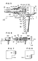
- Fig. 1 is a diagram showing a conventional cubicle;
- Fig. 2 is a diagram showing two adjacent cubicles shown in Fig. 1, with buses provided therein being connected together;
- Fig. 3 is a diagram showing a cubicle, a plurality of which are connected together according to this invention;
- Fig. 4 is a perspective view-showing an enclosed switchgear array according to this invention;
- Fig. 5 is an elevational sectional view showing a connecting device constituting an important part of this invention;
- Fig. 6 is an elevational view partly in section adapted to explain a way of connection utilizing the connecting device shown in Fig. 5; and
- Figs. 7 and 8 are diagrams showing further embodiments of this invention.
- This invention will now be described in detail hereunder with reference to the preferred embodiments illustrated in Figs. 3 through 8.
- In an embodiment shown in Fig. 3, the interior of a
casing 32 of a gas-tight cubicle 31A is separated by a separatingwall 33 into two chambers which are filled with the insulating gas SFs. On the upper side of theseparating wall 33 is provided acircuit breaker 34, the power source side terminals of which are connected through adisconnect switch 35A to powersource side buses 30 which are in turn connected to the lower terminals of T-shaped connectors 36A projecting downwardly through the top wall of thecubicle 31A. On the other hand, the load side terminals of thecircuit breaker 34 are connected through another disconnect switch 35B to acable head 37 of an out-goingcable 38. - In case where a number of the above described
cubicles 31A are arranged to provide an enclosed type switchgear array, the power source side buses in the cubicles are connected together as shown in Figs. 4 and 5. That is, the T-shaped connectors cubicles shaped connectors 36A provided on the upper side of therightmost cubicle 31A. - As shown in Fig. 5, a circular hole 31 a is provided through the top wall of the
cubicle 31A. The downwardly extending portion of the T-shaped connector 36A is inserted through the hole 31a with an O-ring 41 interposed between the connector 36Aand the upper surface of thecubicle 31A. The T-shaped connector 36A is then secured to the top wall of thecubicle 31A by means of bolts and nuts (not shown). - The T-
shaped connector 36 comprises a T-shaped bushing 42 made of, for instance,epoxy resin 42f. An electricallyconductive shielding member 42b and a bar-shaped vertically extendingconductor 42c, whose upper end is driven into theshielding member 42b in thread engagement and whose lower end extends in excess of thebushing 42, are integrally formed with thebushing 42. Amounting base 42e having ashielding portion 42d is also formed integrally with thebushing 42 so that it is secured to the top wall of the cubicle 31Aas described above. The electricallyconductive shielding member 42b has an axially extending through hole of a diameter larger than the outside diameter of a single conductor insulatedcable 39. A pair ofannular grooves 42a are formed around the internal surface of the through hole. Acon-tactor 43 made of an electrically conductive resilient material (such as beryllium copper) formed into a louver-like configuration is inserted in each of theannular grooves 42a. - The
cable 39 is stripped such that aconductor 39a,insulating layer 39b,semi-conductive layer 39c and ashielding layer 39d are exposed in this order in a stepwise manner. Aplug 44 made of an electrically conductive material and generally formed into a frus- toconical configuration formed with an axially extending hole therein is slipped over an end of theconductor 39a. A plurality ofwedge members 45 made of an electrically conductive material are inserted between the circumference of theconductor 39a and the internal surface of the axial hole of theplug 44. Aciampingmember 46 thread-engaging with a part of the axial hole of theplug 44 is driven into the plug hole so that theclamping member 46 forces thewedge members 45 leftwardly as viewed in Fig. 5, so that theplug 44 is firmly secured around the distal end of theconductor 39a. In this manner, a good electrical conductance is assured between theconductor 39a of thecable 39 and the bar-shapedvertical conductor 42c of the T-shaped connector 36 through thewedge members 45,plug 44,contactor 43 and theshielding member 42b. - Between a portion of the
cable 39 inclusive of thesemi-conductive layer 39c and theinsulating layer 39b and theinsulating bushing 42, there is provided astress cone 47 comprising asemi-conductive member 47a and aninsulating member 47b, both formed in an integral manner. An insulating grease is beforehand applied to a part of thestress cone 47 to be inserted into thebushing 42. The insulating grease improves the dielectric strength along the surface of thestress cone 47. Outwardly of thestress cone 47, there is provided aprotective sheath 49 secured by means ofbolts 48 to a leftward end of thebushing 42, with an O-ring 50 interposed between thesheath 49 and thebushing 42. Internally of theprotective sheath 49, there are provided a plurality of screw-threadedrods 49b andcoil springs 49a provided around the screw-threadedrods 49b, respectively. Under the spring forces of thecoil springs 49a, the screw-threadedrods 49b urge thestress cone 47 toward the bushing 42. Theprotective sheath 49,coil springs 49a and the screw-threadedrods 49b as well as other members (not numbered) mating therewith constitute a stress cone pressing device. Asealingtape 51 seals an end of theprotective sheath 49 surrounding thesemiconductive layer 39c of thecable 39. Ablind cover 52 secured to the other end of the insulatingbushing 42 is removed in the case of theconnectors 36B provided on thecubicle 31 B shown in Fig. 4, and an end of a cable similar to thecable 39 is inserted through the end of the insulatingbushing 42 into the corresponding end of the shieldingmember 42b so that the cable is connected to the shieldingmember 42b in the same manner as shown in the leftward half part of Fig. 5. - A procedure for interconnecting buses in the cubicles by use of the above described connector will now be described in detail with reference to Fig. 6 which illustrates a case where the buses in the cubi- des 31 B and 31 C in Fig. 4 are connected together.
- Firstly a
cable 39 of the above described construction is cut into a predetermined length, and both ends of the resultant cable section are stripped stepwisely as shown in Fig. 5. Aplug 44 is secured to an end of the exposedconductor 39a of the cable section by use of thewedge members 45 and the clamping member46 as described hereinbefore. The other end of the cable section is inserted through the shieldingmember 42b of theconnector 36B provided on thecubicle 31 B in a direction indicated by anarrow 60, and two sets to be used with theconnectors 36B and 36C, and each comprising astress cone 47 and aprotective sheath 49 and else constituting the stress cone pressing device, are slipped over a part of the cable section passed in excess of theconnector 36B, so that the two sets are disposed oppositely to each other. Then anotherplug 44 is secured to an end of theconductor 39a exposed on the left side of the cable section by use of thewedge members 45 and the clamping member46. The cable section is further shifted in thearrowed direction 60, so that both ends of the cable section are inserted into the shieldingmembers 42b in theconnectors 36B and 36C, respectively. Thestress cones 47 are then shifted toward theconnectors 36B and 36C and theprotective sheaths 49b are secured to the insulatingbushings 42 of theconnectors 36B and 36C, while thestress cones 47 are pressed by the screw-threadedrods 49b toward thebushings 42 of theconnectors 36B and 36C, respectively. - Although in the above description, the T-shaped connectors are provided through the top wall of the enclosed type cubicles, it is apparent that the connectors may otherwise be provided through a rear wall in an upper part as shown in Fig. 7 orthrough a rearwall in a lower part as shown in Fig. 8. Furthermore, when one or more of the cubicles are desired to be added to an enclosed type switchgear array as described hereinbefore, the blind covers 52 are removed out of the connectors provided on an end cubicle of the switchgear array, and the insulated cables are connected as described above to the shielding members of the connectors without discharging the insulation gas SF6 filling the interior of the cubicles.
- Since the cubicles constituting a switchgear array according to this invention are connected together as described above, there is no necessity of discharging and charging again the insulating gas even in a case where the switchgear array is once disassembled for transportation and the like and assembled again in the installation site. Furthermore, because no bending of the cables is required for the interconnection of the cubicles, the length of the cables can be reduced as desired, and the minimization of the cubicles can be thereby achieved.
Claims (5)
Applications Claiming Priority (4)
| Application Number | Priority Date | Filing Date | Title |
|---|---|---|---|
| JP22650483A JPS60121911A (en) | 1983-11-30 | 1983-11-30 | Connector of electric device to cable |
| JP226504/83 | 1983-11-30 | ||
| JP15718/84 | 1984-01-31 | ||
| JP59015718A JPH0614762B2 (en) | 1984-01-31 | 1984-01-31 | Closed switchboard |
Publications (4)
| Publication Number | Publication Date |
|---|---|
| EP0148394A2 EP0148394A2 (en) | 1985-07-17 |
| EP0148394A3 EP0148394A3 (en) | 1986-10-15 |
| EP0148394B1 EP0148394B1 (en) | 1990-04-04 |
| EP0148394B2 true EP0148394B2 (en) | 1994-08-03 |
Family
ID=26351915
Family Applications (1)
| Application Number | Title | Priority Date | Filing Date |
|---|---|---|---|
| EP84114421A Expired - Lifetime EP0148394B2 (en) | 1983-11-30 | 1984-11-28 | Enclosed switchgears |
Country Status (3)
| Country | Link |
|---|---|
| EP (1) | EP0148394B2 (en) |
| KR (1) | KR900000463B1 (en) |
| DE (1) | DE3481882D1 (en) |
Families Citing this family (13)
| Publication number | Priority date | Publication date | Assignee | Title |
|---|---|---|---|---|
| JP2866473B2 (en) * | 1990-11-20 | 1999-03-08 | 昭和電線電纜株式会社 | Cable plug |
| DE69431270T2 (en) * | 1993-05-12 | 2003-05-08 | Toshiba Kawasaki Kk | Conductive connector for switchgear |
| DE4445082C1 (en) * | 1994-12-08 | 1996-05-09 | Ritz Messwandler Kg | High voltage plug contact |
| JP3588401B2 (en) * | 1995-06-23 | 2004-11-10 | 三菱電機株式会社 | Manufacturing method of insulating spacer and shield electrode |
| FR2767421B1 (en) * | 1997-08-13 | 1999-09-17 | Telecommunications Sa | ELECTRICAL LINK DEVICE WITH FLUID INSULATION |
| FR2788369B1 (en) * | 1999-01-11 | 2001-02-23 | Alstom | CURRENT CROSS-SECTION FOR MEDIUM-VOLTAGE ELECTRIC CELL WITH HERMETIC METAL ENCLOSURE |
| JP4376400B2 (en) * | 2000-01-20 | 2009-12-02 | 三菱電機株式会社 | Busbar connection device between insulated switchboards enclosed with insulating gas |
| DE102006045878A1 (en) * | 2006-09-25 | 2008-04-17 | Siemens Ag | Connecting arrangement for high voltage cables |
| KR200448391Y1 (en) * | 2008-01-31 | 2010-04-08 | 주식회사 평일 | Cable connector for gas insulated switchgear having detecting a voltage |
| DE102014206913A1 (en) * | 2014-04-10 | 2015-10-15 | Siemens Aktiengesellschaft | Switchgear arrangement for a medium-voltage or high-voltage switchgear |
| DE102018211741A1 (en) * | 2018-07-13 | 2020-01-16 | Siemens Aktiengesellschaft | Electrical connector and arrangement with an electrical connector |
| CN109149401B (en) * | 2018-08-20 | 2020-06-30 | 国网江苏省电力公司盐城供电公司 | Cable sealing structure for transformer power distribution cabinet |
| CN111181017B (en) * | 2020-01-10 | 2021-08-24 | 安徽明远电力设备制造有限公司 | Extensible looped netowrk cabinet |
Family Cites Families (3)
| Publication number | Priority date | Publication date | Assignee | Title |
|---|---|---|---|---|
| US3517113A (en) * | 1967-10-05 | 1970-06-23 | Hitachi Cable | Cable insertion unit for use in electric cable joint and terminal |
| US3509518A (en) * | 1968-03-11 | 1970-04-28 | Mc Graw Edison Co | High voltage cable connectors |
| DE2817417A1 (en) * | 1978-04-18 | 1979-10-25 | Krone Gmbh | GAS- OR LIQUID-INSULATED MEDIUM-VOLTAGE SWITCHGEAR, IN PARTICULAR FOR VOLTAGES FROM 1 TO 36 KV |
-
1984
- 1984-11-28 EP EP84114421A patent/EP0148394B2/en not_active Expired - Lifetime
- 1984-11-28 DE DE8484114421T patent/DE3481882D1/en not_active Expired - Lifetime
- 1984-11-30 KR KR1019840007554A patent/KR900000463B1/en not_active IP Right Cessation
Also Published As
| Publication number | Publication date |
|---|---|
| DE3481882D1 (en) | 1990-05-10 |
| EP0148394A2 (en) | 1985-07-17 |
| EP0148394A3 (en) | 1986-10-15 |
| EP0148394B1 (en) | 1990-04-04 |
| KR900000463B1 (en) | 1990-01-30 |
| KR850004365A (en) | 1985-07-11 |
Similar Documents
| Publication | Publication Date | Title |
|---|---|---|
| EP0148394B2 (en) | Enclosed switchgears | |
| MXPA03007475A (en) | Universal power connector for joining flexible cable to rigid devices in any of many configurations. | |
| KR880002575B1 (en) | Circuit breaker system | |
| JPS62233007A (en) | Compact type gas insulated switchgear | |
| CN115280617A (en) | Gas-insulated switchgear | |
| KR20060046058A (en) | An electrical energy disconnection device | |
| DE3564062D1 (en) | Gas-insulated three-phase encapsulated switching installation | |
| US4624520A (en) | Coaxial cable clamp | |
| WO1991011040A1 (en) | Cable connector | |
| JP4313881B2 (en) | Insulated busbar connection structure | |
| US3692921A (en) | Cable coupler | |
| JPH0158725B2 (en) | ||
| CN107567676B (en) | Connection method for cost-effective control of an electric motor | |
| US4320311A (en) | Combination isolating switch and current transformer | |
| US4764123A (en) | Electrical connectors | |
| GB1571720A (en) | Electrical connector | |
| US20220209485A1 (en) | Compact Auxiliary Connector | |
| US3927246A (en) | Three-phase cable termination for metal enclosed compressed gas-insulated substation | |
| US3318992A (en) | Stress relief apparatus | |
| WO2022201493A1 (en) | Solid insulated bus and gas-insulated switchgear provided therewith | |
| JPH0156612B2 (en) | ||
| JP2683787B2 (en) | Cable termination connection | |
| JP3036652B2 (en) | Cable termination connection box | |
| JPH0614762B2 (en) | Closed switchboard | |
| US3244794A (en) | Terminal boxes for electrical apparatus |
Legal Events
| Date | Code | Title | Description |
|---|---|---|---|
| PUAI | Public reference made under article 153(3) epc to a published international application that has entered the european phase |
Free format text: ORIGINAL CODE: 0009012 |
|
| 17P | Request for examination filed |
Effective date: 19841227 |
|
| AK | Designated contracting states |
Designated state(s): DE FR NL |
|
| PUAL | Search report despatched |
Free format text: ORIGINAL CODE: 0009013 |
|
| AK | Designated contracting states |
Kind code of ref document: A3 Designated state(s): DE FR NL |
|
| 17Q | First examination report despatched |
Effective date: 19880426 |
|
| GRAA | (expected) grant |
Free format text: ORIGINAL CODE: 0009210 |
|
| AK | Designated contracting states |
Kind code of ref document: B1 Designated state(s): DE FR NL |
|
| REF | Corresponds to: |
Ref document number: 3481882 Country of ref document: DE Date of ref document: 19900510 |
|
| ET | Fr: translation filed | ||
| PLBI | Opposition filed |
Free format text: ORIGINAL CODE: 0009260 |
|
| 26 | Opposition filed |
Opponent name: KARL PFISTERER ELEKTROTECHNISCHE SPEZIALARTIKEL GM Effective date: 19901222 |
|
| NLR1 | Nl: opposition has been filed with the epo |
Opponent name: KARL PFISTERER ELEKTROTECHNISCHE SPEZIALARTIKEL GM |
|
| PUAH | Patent maintained in amended form |
Free format text: ORIGINAL CODE: 0009272 |
|
| STAA | Information on the status of an ep patent application or granted ep patent |
Free format text: STATUS: PATENT MAINTAINED AS AMENDED |
|
| 27A | Patent maintained in amended form |
Effective date: 19940803 |
|
| AK | Designated contracting states |
Kind code of ref document: B2 Designated state(s): DE FR NL |
|
| ET3 | Fr: translation filed ** decision concerning opposition | ||
| NLR2 | Nl: decision of opposition | ||
| NLR3 | Nl: receipt of modified translations in the netherlands language after an opposition procedure | ||
| APAC | Appeal dossier modified |
Free format text: ORIGINAL CODE: EPIDOS NOAPO |
|
| APAC | Appeal dossier modified |
Free format text: ORIGINAL CODE: EPIDOS NOAPO |
|
| PGFP | Annual fee paid to national office [announced via postgrant information from national office to epo] |
Ref country code: FR Payment date: 20031114 Year of fee payment: 20 |
|
| PGFP | Annual fee paid to national office [announced via postgrant information from national office to epo] |
Ref country code: DE Payment date: 20031126 Year of fee payment: 20 |
|
| PGFP | Annual fee paid to national office [announced via postgrant information from national office to epo] |
Ref country code: NL Payment date: 20031128 Year of fee payment: 20 |
|
| PG25 | Lapsed in a contracting state [announced via postgrant information from national office to epo] |
Ref country code: NL Free format text: LAPSE BECAUSE OF EXPIRATION OF PROTECTION Effective date: 20041128 |
|
| NLV7 | Nl: ceased due to reaching the maximum lifetime of a patent |
Effective date: 20041128 |
|
| APAH | Appeal reference modified |
Free format text: ORIGINAL CODE: EPIDOSCREFNO |