EP0148287A1 - Lock for gripping cords or the like - Google Patents
Lock for gripping cords or the like Download PDFInfo
- Publication number
- EP0148287A1 EP0148287A1 EP83630198A EP83630198A EP0148287A1 EP 0148287 A1 EP0148287 A1 EP 0148287A1 EP 83630198 A EP83630198 A EP 83630198A EP 83630198 A EP83630198 A EP 83630198A EP 0148287 A1 EP0148287 A1 EP 0148287A1
- Authority
- EP
- European Patent Office
- Prior art keywords
- axis
- teeth
- locking
- essentially
- locking member
- Prior art date
- Legal status (The legal status is an assumption and is not a legal conclusion. Google has not performed a legal analysis and makes no representation as to the accuracy of the status listed.)
- Granted
Links
Images


Classifications
-
- F—MECHANICAL ENGINEERING; LIGHTING; HEATING; WEAPONS; BLASTING
- F16—ENGINEERING ELEMENTS AND UNITS; GENERAL MEASURES FOR PRODUCING AND MAINTAINING EFFECTIVE FUNCTIONING OF MACHINES OR INSTALLATIONS; THERMAL INSULATION IN GENERAL
- F16G—BELTS, CABLES, OR ROPES, PREDOMINANTLY USED FOR DRIVING PURPOSES; CHAINS; FITTINGS PREDOMINANTLY USED THEREFOR
- F16G11/00—Means for fastening cables or ropes to one another or to other objects; Caps or sleeves for fixing on cables or ropes
- F16G11/04—Means for fastening cables or ropes to one another or to other objects; Caps or sleeves for fixing on cables or ropes with wedging action, e.g. friction clamps
- F16G11/044—Means for fastening cables or ropes to one another or to other objects; Caps or sleeves for fixing on cables or ropes with wedging action, e.g. friction clamps friction clamps deforming the cable, wire, rope or cord
- F16G11/048—Means for fastening cables or ropes to one another or to other objects; Caps or sleeves for fixing on cables or ropes with wedging action, e.g. friction clamps friction clamps deforming the cable, wire, rope or cord by moving a surface into the cable
Definitions
- This invention relates to locking devices for releasably retaining one or more elongated flexible elements against longitudinal movement in a predetermined direction.
- the invention will be described primarily as applied to a device in which the retained element is a cord or pair of cords or cord ends, though it is to be understood that the invention in its broadest aspects is applicable to other types of flexible elements.
- a first of the parts of the swinging assembly may be considered as an actuating member which is manually operable pivotally between released and active positions, while the second of the two parts may be receivable about a portion of the actuating member in a manner causing the second part to move pivotally with the actuating member but giving it also the desired freedom for relative pivotal movement. Swinging movement of the actuating member then brings two clamping surfaces relatively toward one another to initally clamp the elongated flexible element against relative longitudinal movement, and further pivotal movement of the second part of the assembly relative to the actuating member tightens the gripping action.
- a prior art locking device which has been in use for a number of years for retaining two cords or cord ends against longitudinal movement includes two metal parts which swing relative to one another between active cord gripping and released positions, with one of the parts having a loop projecting through a slit in the other part in the active locking condition for reception of the padlock, and with the two parts being cammed relative to one another to grip cords therebetween.
- the present invention provides an improved.locking device for gripping an elongated element or elements, and which in its preferred form is especially adapted for gripping two cords or cord ends, typically the opposite ends of a drawstring of a bag or the like.
- the device desirably utilizes a two-part swinging locking assembly of the general type shown in my above mentioned United States Patent application 6/136,406, but with improvements directed toward maximizing the facility of operation and gripping effectiveness when used as a cord lock, while at the same time attaining a very substantial load carrying capacity and a structural strength assuring satisfactory and reliable operation of the device over a long period of time.
- the mentioned surface or face against which the locking member of the two part swinging locking assembly presses the cords in their locking condition preferably forms an essentially curving wall of a recess into which the locking member urges the cords.
- the mentioned surface or face desirably has a series of teeth which engage the cords in a relation increasing the resistance to longitudinal movement thereof in the locked condition of the parts, but with those teeth preferably being smaller than opposed teeth formed on the locking member itself.
- the two cords may be directed into properly spaced essentially parallel relation by reception within two spaced locating grooves or recesses formed in the locking member, and/or by a projection formed on a member of the device and projecting toward the locking member at a location between the two cords.
- the actuating arm may be retained in its locking position by a detenting arrangement including a detent part projecting from one of the coacting members and engageable with a structure formed on the other member, with these detenting parts preferably being located between two guideways formed on one of the members and through which the two cords extend.
- a loop for receiving a padlock and holding the parts in locked condition may project from one of the members and through a slit in the actuating member or arm, at a location between the axis of swinging movement of the parts and the detenting elements.
- a locking device embodying the present invention is designated generally by the number 10 in the drawings, and is adapted to be utilized for preventing longitudinal movement of a pair of flexible cords 11, which may be either separate cords or opposite ends of a single drawstring of a mail bag, garment or the like.
- the device when in its locked conditions prevents movement of the cords in a rightward direction as viewed in Figs. 1 and 2.
- the cord lock 10 includes a first part or member 12 having a label or card holding frame 13 at its underside as viewed in Fig. 2, and an assembly 14 connected to member 12 by a hinge structure 15 for relative pivotal movement about an axis 16 between the full line locking position of Fig. 2 and the broken line released position of that figure.
- Assembly 14 includes an actuating member 17 and a locking member 18 which is free for limited pivotal movement relative to member 17 and about axis 16.
- Member 12 has, near its right end as viewed in Figs. 1 and 2, two opposite side walls 19 and 20 extending parallel to one another and to a central longitudinal plane 21.
- the device will be described in the present specification as positioned to have plane 21 and side walls 19 and 20 in vertically extending condition.
- Walls 19 and 20 project upwardly from opposite sides of a horizontal bottom wall 22 of member 12, and may be formed integrally therewith.
- the two side walls 19 and 20 may be defined by directly vertical forward edges 23, horizontal top edges 24, and inclined rear edges 25, with the bottom wall 22 projecting leftwardly beyond these side walls to a transverse end 26 of the bottom wall.
- Cords 11 extend essentially parallel to one another in laterally spaced relation above bottom wall 22, and in the Fig.
- the label or card holder 13 is rectangular and extends along the periphery of member 12 at its underside, and has two parallel opposite side portions 31 received and secured within grooves 32 formed in the side edges of member 12, and two transverse end portions 33 received and secured within end grooves 34 in member 12.
- the card holding frame 13 may be secured to member 12 in any appropriate manner as by fusion bonding the upper surfaces of portions 32 and 33 of member 13 along their entire length to member 12 by ultrasonic welding.
- the side portions 31 of card holder 13 project downwardly beneath the level of horizontal undersurface 35 of member 12 to form two flanges 36 defining guideways 37 within which the opposite edges of a card 38 are receivable, with a rounded projection or projections 39 of part 12 projecting downwardly in a relation engaging and slightly deforming the central portion of the card to frictionally retain it in the guideway formed between flanges 36.
- a name, address, or other identification can be printed on card 38 to identify the item to which cords 11 and the lock device 10 are attached.
- the swinging actuating member 17 forms an arm which extends generally horizontally in the Fig. 2 locked position of the parts, and which is manually engageable at its leftward extremity 40 to swing member 17 in either direction between its full line and broken line positions.
- Member 17 may be considered as having a wall 41 which is generally horizontal in the Fig. 2 full line position of the parts, and more particularly which may extend first approximately directly horiztonally from its left handle end to a location 42; then curve gradually downwardly to a location 43, and then advance back upwardly at an inclination from the location 43 to a point 44.
- Strengthening or stiffening ribs 45 may extend along and project upwardly a short distance from the opposite side edges of wall 41 of actuating member 17.
- wall 41 of member 17 contains a slot 46 which is elongated essentially parallel to the main longitudinal axis 21 of member 12, and which in the F ig. 2 full line position of member 17 receives a padlock loop 47 formed integrally with and projecting upwardly from bottom wall 22 of member 12.
- Loop 47 contains an opening 147 adapted to receive the locking portion 48 of a padlock 49 at a location above actuating member 17 to lock member 17 in its Fig. 2 full line position and against upward cord releasing movement.
- the lowest portion 43 of wall 41 of actuating member 17 is located to engage portion 48 of the padlock in the locking condition of the parts.
- the left end 40 of member 17 is spaced above bottom wall 22 of member 12 and above cords 11 to allow easy manual actuation of member 17 upwardly from the locking condition to released condition, as by manually grasping handle end 40 of member 17 and moving it upwardly or by inserting a user's thumb beneath end 40 and flipping it upwardly while holding the cords in the rest of the user's hand.
- member 17 has an externally cylindrical pivot pin portion 50 whose outer cylindrical surface 51 is centered about pivotal axis 16, and whose opposite ends 52 and 53 function as cylindrical pivot lugs projecting into corresponding cylindrical openings 54 and 55 in side walls 19 and 20 centered about axis 16 to effectively mount part 17 for its discussed swinging movement.
- Parts 12, 17, 18 and 13 are preferably all formed of an appropriate essentially stiff or rigid resinous plastic material adapted to effectively maintain the illustrated shape configuration but resiliently deformable during assembly to enable the parts to be snapped together.
- the part 17 during assembly is adapted to be forced downwardly'between side walls 19 and 20 and to cam those side walls relatively apart far enough to allow pivot lugs 52 and 53 to snap into openings 54 and 55 in the side walls to complete the desired hinge connection.
- pivot lugs 52 and 53 are so configured that, when member 17 is in the upwardly projecting position represented in broken lines in Fig. 2, which position is represented in full lines in Fig.
- two downwardly and inwardly inclined semicircular cam surfaces 56 formed on the outer ends of pivot lugs 52 and 53 are engageable with correspondingly downwardly and inwardly inclined cam surfaces 57 formed at the inner sides of side walls 19 1 land 20 above openings 54 and 55 to deflect or cam walls 19 and 20 relatively apart as the cylindrical portion 50 of the member 17 is pushed downwardly (see broken line condition of Fig. 5), with those side walls then springing back by their own resilience to their initial vertical parallel condition when the pivot lug ends 52 and 53 of portion 50 reach a position of alignment with openings 54 and 55.
- the cylindrical external surface 51 of pivot pin or shaft portion 50 of part 17 may be continuous along the entire length of portion 50, or may be interrupted at locations typically represented at 58 for lightening purposes (Fig. 10).
- member 17 may have a portion 59 which is somewhat thicker than the discussed wall 41 of member 17 leftwardly of point 44, and which may be of a width to be closely received and confined between the inner parallel vertical surfaces 61 of side walls 19 and 20 to locate part 17 against move- :nent along axis 16 relative to part 12.
- member 12 Near its left end, member 12 has an upwardly projecting wall 62 (Figs. 8 and 9) which is molded to contain and form two guideway passages 63 and 64 dimensioned to receive and closely confine and locate cords 11 to position them in a desired laterally spaced relation at the left end of the device. Between these guideways 63 and 64, wall 62 has a detenting portion 65 with a horizontal undersurface 66 engageable with a detent lug or finger 67 projecting downwardly from and formed integrally with member 17. Lug 67 and portion 65 of wall 62 may have the cross section illustrated in Fig.
- lug 67 may have a camming rib or projection 68 extending along the lower edge portion of projection 67 and having an upper latching surface 69 inclined at a slight angle to the horizontal (preferably 10 degrees) and a lower inclined camming surface 70, with a vertical surface 71 extending therebetween.
- cam surface 70 Upon downward swinging movement of member 17 toward the Fig. 2 full line position, cam surface 70 first engages an inclined camming edge 72 formed on portion 65 of member 12 to deflect lug 67 slightly leftwardly as it moves past edge 72 and ultimately reaches the full line position of Fig.
- a slit 73 may be formed in member 17 at the location of detenting lug or projection 67 to facilitate formation of that detenting projection in an injection molding process.
- Locking element 18 like the other parts is preferably formed of essentially stiff but slightly resiliently deformable resinous plastic material, and is configured to slide axially onto and be carried by the cylindrical pivot pin portion 50 of member 17.
- Part 18 may extend the entire distance between the inner parallel surfaces 61 of side walls 19 and 20 of member 12, and may have parallel vertical end surfaces 74 engageable with surfaces 61 to effectively locate locking element 18 against movement along axis 16.
- Element 18 may have the configuration illustrated in Fig. 7 through the entire axial extent of element 18 between side walls 19 and 20, except at the location of two spaced grooves 75 which extend arcuately about axis 16 and may have the sectional configuration illustrated in Fig. 5.
- grooves 75 are located symmetrically with respect to central vertical plane 21 of the device, at opposite sides thereof, and are so positioned as to receive upper portions of the two cords 11 when member 17 is in the upwardly projecting position represented in broken lines in Fig. 2 and in full lines in Fig. 5 (see also broken line position represented at 75 in Fig. 4).
- a projection 76 formed integrally with and projecting upwardly from bottom wall 22 of member 12 is located generally opposite the arcuate portion 77 of element 18 formed between the two grooves 75, to coact with those grooves in defining passageways at opposite sides of lug 76 and portion 77 within which the two cords are received.
- Lug 76 may have an upper semicircularly curved edge 176 engageable with the cords to hold them in spaced relation. Such retention of the cords by lug 76 and portion 77 of element 18 in positions near the two side walls 19 and 20 of part 12 minimizes the internal stresses which are developed in portion 28 of member 12 when the cords are under tension.
- Element 18 has an internal cylindrically curving surface 78 which corresponds to and is a close fit about external cylindrical surface 51 of pivot pin portion 50 of member 17, to mount part 18 for pivotal movement relative to part 17 about axis 16 through a very limited angle (preferably 45°) determined by the width arcuately about axis 16 of a gap formed between two edges 79 and 80 of part 18
- element 18 can swing relative to part 17 between a position in which the undersurface of portion 59 of member 17 engages edge 80 of element 18 (full lines in Figs. 2 and 7) and a position in which the upper surface of portion 59 engages upper edge 79 of the gap in element 18.
- element 18 has a series of gripping teeth 81, which are movable between the broken line released position of Fig. 2 and the full line cord gripping position of that figure. These teeth extend parallel to the pivotal axis 16 of parts 17 and 18 and in the locking position are received opposite the gripping face 30 formed in the upper side of member 12.
- That member has an upwardly projecting wall 82 which may extend directly vertically in the full line position of Fig. 2 and which may have the vertical cross section illustrated in Fig. 6 to define portions 83 extending laterally above the upper edges of side walls 19 and 20 and portions 84 projecting downwardly at the outer sides of those side walls to block unwanted forced spreading of walls 19 and 20 relatively apart to attain the anti-tampering effect disclosed'in my copending United States Application Serial Number 122,604 filed February 19, 1980 entitled "Cord Locks or the Like Resistant to Tampering".
- the outer downwardly projecting flanges or lugs 84 on member 17 are located entirely above the upper edges of side walls 19 and 20 and do not interfere with spreading movement of those side walls as member 17 is snapped downwardly to its assembled condition between those walls.
- lugs 84 move to positions at the outside of the two side walls 19 and 20 to confine those walls against spreading movement. If the walls 19 and 20 are forced apart in the Fig. 2 condition, this action will necessarily result in breakage of projections 84 and indicate to a subsequent user that the device has been violated.
- the teeth 81 formed on the underside of locking member 18 and the opposed toothed gripping face 30 of member 12 are preferably of uniform cross section transversely of axis 16 through the entire axial extent between side walls 19 and 20. Further, the vertical cross section of the remainder of the gripping portion 28 of member 12, forwardly and rearwardly of the toothed gripping face 30, is uniform along the entire axial distance between walls 19 and 20 except at the location or the previously discussed cord separating lug 76 on member 12. More particularly, except at the location of that lug, the upper surfaces 85 of portion 28 of member 12 may be horizontal, with the curved gripping face 30 being recessed downwardly beneath the level of those horizontal surfaces 85.
- the different teeth 81 of locking member 18 are preferably not centered about the pivotal axis 16 and are not a uniform radial distance from that axis. Instead, these teeth are preferably centered about a second axis 86, which is parallel to but spaced laterally from axis 16 and which in the Fig. 2 full line position of the parts is offset directly leftwardly from axis 16 and in the same horizontal plane 87 as that axis.
- the peaks 88 of the different teeth 81 thus follow or define the curving pattern 89 represented in Fig. 7 extending about axis 86 and eccentrically with respect to main pivotal axis 16.
- the circularly leading one of the teeth 81, designated as tooth 81a in Fig. 7, is thus substantially closer to pivotal axis 16 than is the next successive tooth 81b, with the succeeding teeth advancing progressively farther away from axis 16.
- teeth 90 of gripping face 30 of part 12, and the face defined by those teeth are also arranged in a pattern which is preferably curved essentially arcuately but not centered with respect to pivotal axis 16.
- These teeth 90 are preferably smaller than teeth 81 of locking member 18, so that the radial dimension of teeth 90 is less than the radial dimension of teeth 81, and the circular spacing between successive teeth 90 is less than the circular spacing between successive teeth 81.
- Teeth 90 have a radius greater than teeth 81, and are preferably centered about an axis or axes spaced farther from pivotal axis 16 than is the axis 86 of teeth 81.
- the teeth 90 may be considered as having no effective curvature about either of the axes 93 and 96, so that in effect a line 190 joining the peaks of teeth 90 between those locations 92 and 94 may extend directly horizontally and parallel to plane 87.
- the curved pattern defined by the peaks of teeth 90 between the locations 91 and 92 (centered about axis 93) is indicated at 97 in Fig. 7, and the curved pattern defined by the teeth 90 between the locations 94 and 95 and about axis 96 is represented at 98.
- member 17 may be swung upwardly about axis 16 relative to member 12 to the broken line position of Fig. 2, with corresponding swinging movement of the connected element 18 to its broken line position of the figure, enabling insertion of cords 11 leftwardly through the gap formed vertically between element 18 and the upwardly facing toothed gripping portion 28 of member 12.
- the cords are advanced leftwardly along the upper surface of member 12 and through the guideways 63 and 64 formed in structure 62 to maintain them in located parallel relation as they project leftwardly beyond the locking device.
- actuating member 17 can be swung downwardly from its broken line position or Fig. 2 to its full line position of that figure, with portion 59 of member 17 engaging edge 80 of member 18 and causing it to swing from its broken line position of Fig. 2 to its full line position of Figs. 2 and 7 bringing teeth 81 into engagement with the cords and thereby clamping the cords into the recess formed by gripping face 30 and against the curved series of teeth 90 in that recess.
- detenting lug 67 on part 17 is deflected by portion 65 of wall 62 and then returns to a position releasably retaining member 17 in its locking position of Fig. 2.
- the parts 17 and 12 are retained in their locking condition by insertion of the hasp 48 of padlock 49 through loop 47 at a location above actuating arm 17.
- the unique recessed and curved configuration of the toothed gripping face 30 of member 12, in conjunection with teeth 81 of element 18, has the effect of maximizing the resistance offered to rightward movement of the cords in the locked condition of the device, and at the same time causing the internal stresses in member 12 to be taken primarily by its lower heavy portion 28 with minimum internal stresses in walls 19 and 20.
Abstract
Description
- This invention relates to locking devices for releasably retaining one or more elongated flexible elements against longitudinal movement in a predetermined direction. The invention will be described primarily as applied to a device in which the retained element is a cord or pair of cords or cord ends, though it is to be understood that the invention in its broadest aspects is applicable to other types of flexible elements.
- United States Patent Application Serial Number 6/136,406 filed April 1, 1980 on "Device for Gripping an Elongated Flexible Element" discloses a locking device in which a gripping action on a belt or other elongated flexible element is attained by provision of a swinging locking assembly consisting of two parts which swing together relative to another member and which also are free for limited pivotal movement relative to one another in a final take-up or clamping action. A first of the parts of the swinging assembly may be considered as an actuating member which is manually operable pivotally between released and active positions, while the second of the two parts may be receivable about a portion of the actuating member in a manner causing the second part to move pivotally with the actuating member but giving it also the desired freedom for relative pivotal movement. Swinging movement of the actuating member then brings two clamping surfaces relatively toward one another to initally clamp the elongated flexible element against relative longitudinal movement, and further pivotal movement of the second part of the assembly relative to the actuating member tightens the gripping action.
- A prior art locking device which has been in use for a number of years for retaining two cords or cord ends against longitudinal movement includes two metal parts which swing relative to one another between active cord gripping and released positions, with one of the parts having a loop projecting through a slit in the other part in the active locking condition for reception of the padlock, and with the two parts being cammed relative to one another to grip cords therebetween.
- The present invention provides an improved.locking device for gripping an elongated element or elements, and which in its preferred form is especially adapted for gripping two cords or cord ends, typically the opposite ends of a drawstring of a bag or the like. The device desirably utilizes a two-part swinging locking assembly of the general type shown in my above mentioned United States Patent application 6/136,406, but with improvements directed toward maximizing the facility of operation and gripping effectiveness when used as a cord lock, while at the same time attaining a very substantial load carrying capacity and a structural strength assuring satisfactory and reliable operation of the device over a long period of time.
- Some of the advantages of the device are attained by improvements in the configuration of the surface or face against which the locking member of the two part swinging locking assembly presses the cords in their locking condition. That surface preferably forms an essentially curving wall of a recess into which the locking member urges the cords. Also, the mentioned surface or face desirably has a series of teeth which engage the cords in a relation increasing the resistance to longitudinal movement thereof in the locked condition of the parts, but with those teeth preferably being smaller than opposed teeth formed on the locking member itself. During initial threading of the cords through the locking device, the two cords may be directed into properly spaced essentially parallel relation by reception within two spaced locating grooves or recesses formed in the locking member, and/or by a projection formed on a member of the device and projecting toward the locking member at a location between the two cords.
- The actuating arm may be retained in its locking position by a detenting arrangement including a detent part projecting from one of the coacting members and engageable with a structure formed on the other member, with these detenting parts preferably being located between two guideways formed on one of the members and through which the two cords extend. A loop for receiving a padlock and holding the parts in locked condition may project from one of the members and through a slit in the actuating member or arm, at a location between the axis of swinging movement of the parts and the detenting elements.
- The above and other features and objects of the invention will be better understood from the following detailed description of the typical embodiment illustrated in the accompanying drawings in which:
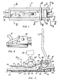
- Fig. 1 is a plan view of a cord lock constructed in accordance with the invention;
- Fig. 2 is a vertical section taken on line 2-2 of Fig. 1;
- Fig. 3 is a fragmentary side elevational view taken on line 3-3 of Fig. 1;
- Fig. 4 is an end elevational view taken on line 4-4 of Fig. 1:
- Figs. 5 and 6 are vertical sections taken on line 5-5 and 6-6 respectively of Fig. 1;
- Fig. 7 is an enlarged fragmentary view representing a portion of Fig. 2;
- Figs. 8 and 9 are vertical sections taken on lines 8-8 and 9-9 of Fig. 1; and
- Fig. 10 is a reduced fragmentary vertical section taken on line 10-10 of Fig. 7.
- A locking device embodying the present invention is designated generally by the
number 10 in the drawings, and is adapted to be utilized for preventing longitudinal movement of a pair of flexible cords 11, which may be either separate cords or opposite ends of a single drawstring of a mail bag, garment or the like. The device when in its locked conditions prevents movement of the cords in a rightward direction as viewed in Figs. 1 and 2. - The
cord lock 10 includes a first part ormember 12 having a label orcard holding frame 13 at its underside as viewed in Fig. 2, and anassembly 14 connected tomember 12 by a hinge structure 15 for relative pivotal movement about anaxis 16 between the full line locking position of Fig. 2 and the broken line released position of that figure.Assembly 14 includes an actuating member 17 and alocking member 18 which is free for limited pivotal movement relative to member 17 and aboutaxis 16. -
Member 12 has, near its right end as viewed in Figs. 1 and 2, twoopposite side walls longitudinal plane 21. The device will be described in the present specification as positioned to haveplane 21 andside walls Walls horizontal bottom wall 22 ofmember 12, and may be formed integrally therewith. As seen in Fig. 3, the twoside walls forward edges 23, horizontaltop edges 24, and inclinedrear edges 25, with thebottom wall 22 projecting leftwardly beyond these side walls to atransverse end 26 of the bottom wall. Cords 11 extend essentially parallel to one another in laterally spaced relation abovebottom wall 22, and in the Fig. 2 position of the parts may rest on and be supported by a horizontal planar orupper surface 27 of bottom wall Z2 except at the location of an upwardly projecting grippingportion 28 formed onbody 12 at its right end. Thisportion 28 defines arecess 29 into which gripped portions of cords 11 are pressed downwardly by lockingmember 18 and against an essentially curving gripping surface orface 30 forming a wall of the recess. The precise configuration which is desirably given to grippingface 30 will be described in greater detail at a later point. - The label or
card holder 13 is rectangular and extends along the periphery ofmember 12 at its underside, and has two parallelopposite side portions 31 received and secured withingrooves 32 formed in the side edges ofmember 12, and twotransverse end portions 33 received and secured withinend grooves 34 inmember 12. Thecard holding frame 13 may be secured to member 12 in any appropriate manner as by fusion bonding the upper surfaces ofportions member 13 along their entire length tomember 12 by ultrasonic welding. - The
side portions 31 of card holder 13 project downwardly beneath the level ofhorizontal undersurface 35 ofmember 12 to form twoflanges 36 definingguideways 37 within which the opposite edges of acard 38 are receivable, with a rounded projection orprojections 39 ofpart 12 projecting downwardly in a relation engaging and slightly deforming the central portion of the card to frictionally retain it in the guideway formed betweenflanges 36. A name, address, or other identification can be printed oncard 38 to identify the item to which cords 11 and thelock device 10 are attached. - The swinging actuating member 17 forms an arm which extends generally horizontally in the Fig. 2 locked position of the parts, and which is manually engageable at its
leftward extremity 40 to swing member 17 in either direction between its full line and broken line positions. Member 17 may be considered as having awall 41 which is generally horizontal in the Fig. 2 full line position of the parts, and more particularly which may extend first approximately directly horiztonally from its left handle end to alocation 42; then curve gradually downwardly to a location 43, and then advance back upwardly at an inclination from the location 43 to apoint 44. Strengthening or stiffening ribs 45 may extend along and project upwardly a short distance from the opposite side edges ofwall 41 of actuating member 17. At a central location,wall 41 of member 17 contains aslot 46 which is elongated essentially parallel to the mainlongitudinal axis 21 ofmember 12, and which in the Fig. 2 full line position of member 17 receives apadlock loop 47 formed integrally with and projecting upwardly frombottom wall 22 ofmember 12.Loop 47 contains anopening 147 adapted to receive the locking portion 48 of apadlock 49 at a location above actuating member 17 to lock member 17 in its Fig. 2 full line position and against upward cord releasing movement. The lowest portion 43 ofwall 41 of actuating member 17 is located to engage portion 48 of the padlock in the locking condition of the parts. In that condition, theleft end 40 of member 17 is spaced abovebottom wall 22 ofmember 12 and above cords 11 to allow easy manual actuation of member 17 upwardly from the locking condition to released condition, as by manually graspinghandle end 40 of member 17 and moving it upwardly or by inserting a user's thumb beneathend 40 and flipping it upwardly while holding the cords in the rest of the user's hand. - At its right end, member 17 has an externally cylindrical
pivot pin portion 50 whose outercylindrical surface 51 is centered aboutpivotal axis 16, and whoseopposite ends cylindrical openings side walls axis 16 to effectively mount part 17 for its discussed swinging movement.Parts parts 12 and 17 in particular, the part 17 during assembly is adapted to be forced downwardly'betweenside walls pivot lugs openings pivot lugs semicircular cam surfaces 56 formed on the outer ends ofpivot lugs side walls 19 1land 20 aboveopenings cam walls cylindrical portion 50 of the member 17 is pushed downwardly (see broken line condition of Fig. 5), with those side walls then springing back by their own resilience to their initial vertical parallel condition when the pivot lug ends 52 and 53 ofportion 50 reach a position of alignment withopenings external surface 51 of pivot pin orshaft portion 50 of part 17 may be continuous along the entire length ofportion 50, or may be interrupted at locations typically represented at 58 for lightening purposes (Fig. 10). Extending between thecylindrical portion 50 of member 17 and thepoint 44, member 17 may have aportion 59 which is somewhat thicker than the discussedwall 41 of member 17 leftwardly ofpoint 44, and which may be of a width to be closely received and confined between the inner parallelvertical surfaces 61 ofside walls axis 16 relative topart 12. - Near its left end,
member 12 has an upwardly projecting wall 62 (Figs. 8 and 9) which is molded to contain and form twoguideway passages 63 and 64 dimensioned to receive and closely confine and locate cords 11 to position them in a desired laterally spaced relation at the left end of the device. Between theseguideways 63 and 64,wall 62 has adetenting portion 65 with ahorizontal undersurface 66 engageable with a detent lug orfinger 67 projecting downwardly from and formed integrally with member 17.Lug 67 andportion 65 ofwall 62 may have the cross section illustrated in Fig. 8 along the entire lateral extent oflug 67, and inparticular lug 67 may have a camming rib orprojection 68 extending along the lower edge portion ofprojection 67 and having anupper latching surface 69 inclined at a slight angle to the horizontal (preferably 10 degrees) and a lower inclined camming surface 70, with a vertical surface 71 extending therebetween. Upon downward swinging movement of member 17 toward the Fig. 2 full line position, cam surface 70 first engages aninclined camming edge 72 formed onportion 65 ofmember 12 to deflectlug 67 slightly leftwardly as it moves pastedge 72 and ultimately reaches the full line position of Fig. 8 in which the resilience ofprojection 67 causes it to return rightwardly to that full line position for engagement of camming rib orhook 68 with theundersurface 66 ofportion 65 ofwall 62 to effectively detent or latch the member 17 in its full line position of Fig. 2 and against upward swinging movement from that position. The resilience ofprojection 67 is however such that if member 17 is manually forced upwardly relative tomember 12, the engagement of the inclinedupper surface 69 ofrib 68 with the undersurface ofdetenting wall 62 will camprojection 67 leftwardly in a manner enabling the projection to move upwardlypast wall 62 for swinging movement of member 17 to its broken line position of Fig. 2. A slit 73 may be formed in member 17 at the location of detenting lug orprojection 67 to facilitate formation of that detenting projection in an injection molding process. - Locking
element 18 like the other parts is preferably formed of essentially stiff but slightly resiliently deformable resinous plastic material, and is configured to slide axially onto and be carried by the cylindricalpivot pin portion 50 of member 17.Part 18 may extend the entire distance between the innerparallel surfaces 61 ofside walls member 12, and may have parallelvertical end surfaces 74 engageable withsurfaces 61 to effectively locatelocking element 18 against movement alongaxis 16.Element 18 may have the configuration illustrated in Fig. 7 through the entire axial extent ofelement 18 betweenside walls grooves 75 which extend arcuately aboutaxis 16 and may have the sectional configuration illustrated in Fig. 5. Thesegrooves 75 are located symmetrically with respect to centralvertical plane 21 of the device, at opposite sides thereof, and are so positioned as to receive upper portions of the two cords 11 when member 17 is in the upwardly projecting position represented in broken lines in Fig. 2 and in full lines in Fig. 5 (see also broken line position represented at 75 in Fig. 4). Aprojection 76 formed integrally with and projecting upwardly frombottom wall 22 ofmember 12 is located generally opposite thearcuate portion 77 ofelement 18 formed between the twogrooves 75, to coact with those grooves in defining passageways at opposite sides oflug 76 andportion 77 within which the two cords are received.Lug 76 may have an upper semicircularlycurved edge 176 engageable with the cords to hold them in spaced relation. Such retention of the cords bylug 76 andportion 77 ofelement 18 in positions near the twoside walls part 12 minimizes the internal stresses which are developed inportion 28 ofmember 12 when the cords are under tension. -
Element 18 has an internal cylindrically curvingsurface 78 which corresponds to and is a close fit about externalcylindrical surface 51 ofpivot pin portion 50 of member 17, to mountpart 18 for pivotal movement relative to part 17 aboutaxis 16 through a very limited angle (preferably 45°) determined by the width arcuately aboutaxis 16 of a gap formed between two edges 79 and 80 ofpart 18 As will be understood,element 18 can swing relative to part 17 between a position in which the undersurface ofportion 59 of member 17 engages edge 80 of element 18 (full lines in Figs. 2 and 7) and a position in which the upper surface ofportion 59 engages upper edge 79 of the gap inelement 18. At its underside,element 18 has a series of gripping teeth 81, which are movable between the broken line released position of Fig. 2 and the full line cord gripping position of that figure. These teeth extend parallel to thepivotal axis 16 ofparts 17 and 18 and in the locking position are received opposite the grippingface 30 formed in the upper side ofmember 12. - At the left end of
portion 59 of member 17, that member has an upwardly projectingwall 82 which may extend directly vertically in the full line position of Fig. 2 and which may have the vertical cross section illustrated in Fig. 6 to defineportions 83 extending laterally above the upper edges ofside walls portions 84 projecting downwardly at the outer sides of those side walls to block unwanted forced spreading ofwalls side walls side walls walls projections 84 and indicate to a subsequent user that the device has been violated. - Referring now to Fig. 7, the teeth 81 formed on the underside of locking
member 18 and the opposed toothed grippingface 30 ofmember 12 are preferably of uniform cross section transversely ofaxis 16 through the entire axial extent betweenside walls portion 28 ofmember 12, forwardly and rearwardly of the toothed grippingface 30, is uniform along the entire axial distance betweenwalls cord separating lug 76 onmember 12. More particularly, except at the location of that lug, theupper surfaces 85 ofportion 28 ofmember 12 may be horizontal, with the curvedgripping face 30 being recessed downwardly beneath the level of thosehorizontal surfaces 85. - The different teeth 81 of locking
member 18 are preferably not centered about thepivotal axis 16 and are not a uniform radial distance from that axis. Instead, these teeth are preferably centered about asecond axis 86, which is parallel to but spaced laterally fromaxis 16 and which in the Fig. 2 full line position of the parts is offset directly leftwardly fromaxis 16 and in the same horizontal plane 87 as that axis. Thepeaks 88 of the different teeth 81 thus follow or define the curving pattern 89 represented in Fig. 7 extending aboutaxis 86 and eccentrically with respect to mainpivotal axis 16. The circularly leading one of the teeth 81, designated as tooth 81a in Fig. 7, is thus substantially closer topivotal axis 16 than is the nextsuccessive tooth 81b, with the succeeding teeth advancing progressively farther away fromaxis 16. - The teeth 90 of gripping
face 30 ofpart 12, and the face defined by those teeth, are also arranged in a pattern which is preferably curved essentially arcuately but not centered with respect topivotal axis 16. These teeth 90 are preferably smaller than teeth 81 of lockingmember 18, so that the radial dimension of teeth 90 is less than the radial dimension of teeth 81, and the circular spacing between successive teeth 90 is less than the circular spacing between successive teeth 81. Teeth 90 have a radius greater than teeth 81, and are preferably centered about an axis or axes spaced farther frompivotal axis 16 than is theaxis 86 of teeth 81. In the preferred arrangement, a first series of the teeth 90, between the locations 91 and 92 of Fig. 7, are centered about anaxis 93 which is parallel to and offset leftwardly frompivotal axis 16, while a second series of the teeth 90 betweenlocations 94 and 95 may be centered about adifferent axis 96 which is slightly closer toaxis 16 than isaxis 93, but is slightly farther fromaxis 16 than isaxis 86. In the Fig. 2 full line position of the parts, all of theseaxes axes line 190 joining the peaks of teeth 90 between those locations 92 and 94 may extend directly horizontally and parallel to plane 87. The curved pattern defined by the peaks of teeth 90 between the locations 91 and 92 (centered about axis 93) is indicated at 97 in Fig. 7, and the curved pattern defined by the teeth 90 between thelocations 94 and 95 and aboutaxis 96 is represented at 98. - In initially placing the assembled device in use, member 17 may be swung upwardly about
axis 16 relative tomember 12 to the broken line position of Fig. 2, with corresponding swinging movement of the connectedelement 18 to its broken line position of the figure, enabling insertion of cords 11 leftwardly through the gap formed vertically betweenelement 18 and the upwardly facing toothed grippingportion 28 ofmember 12.Grooves 75 in lockingmember 18 and the intermediate increaseddiameter portion 77 of that part, coacting with the upwardly projectinglug 76 ofmember 12, form guideways into which the two cords may be easily inserted for threading between the parts. The cords are advanced leftwardly along the upper surface ofmember 12 and through theguideways 63 and 64 formed instructure 62 to maintain them in located parallel relation as they project leftwardly beyond the locking device. After the cords have been inserted in this manner, actuating member 17 can be swung downwardly from its broken line position or Fig. 2 to its full line position of that figure, withportion 59 of member 17 engaging edge 80 ofmember 18 and causing it to swing from its broken line position of Fig. 2 to its full line position of Figs. 2 and 7 bringing teeth 81 into engagement with the cords and thereby clamping the cords into the recess formed by grippingface 30 and against the curved series of teeth 90 in that recess. Subsequent exertion of rightward longitudinal force on the cords tends to cause counterclockwise pivotal movement ofmember 18 relative to member 17 and aboutaxis 16, which pivotal movement acts by virtue of the eccentric configuration of both the teeth 81 of member 17 and the teeth 90 ofmember 12 to move the teeth 81 progressively closer to teeth 90 and thereby grip the cords progressively more tightly. An automatic tightening action is thus attained, effectively and very positively preventing rightward withdrawal of the cords from between the two gripping surfaces. The above discussed specifically defined configuration of those toothed surfaces optimizes the gripping action. During the final portion of the downward swinging movement of the actuating member 17,detenting lug 67 on part 17 is deflected byportion 65 ofwall 62 and then returns to a position releasably retaining member 17 in its locking position of Fig. 2. Theparts 17 and 12 are retained in their locking condition by insertion of the hasp 48 ofpadlock 49 throughloop 47 at a location above actuating arm 17. The unique recessed and curved configuration of the toothed grippingface 30 ofmember 12, in conjunection with teeth 81 ofelement 18, has the effect of maximizing the resistance offered to rightward movement of the cords in the locked condition of the device, and at the same time causing the internal stresses inmember 12 to be taken primarily by its lowerheavy portion 28 with minimum internal stresses inwalls - While a certain specific embodiment of the present invention has been disclosed as typical, the invention is of course not limited to this particular form, but rather is applicable broadly to all such variations as fall within the scope of the appended claims.
Claims (11)
Priority Applications (3)
| Application Number | Priority Date | Filing Date | Title |
|---|---|---|---|
| DE198383630198T DE148287T1 (en) | 1983-12-05 | 1983-12-05 | CLASP FOR ROPES OR THE LIKE. |
| DE8383630198T DE3376448D1 (en) | 1983-12-05 | 1983-12-05 | Lock for gripping cords or the like |
| EP83630198A EP0148287B1 (en) | 1983-12-05 | 1983-12-05 | Lock for gripping cords or the like |
Applications Claiming Priority (1)
| Application Number | Priority Date | Filing Date | Title |
|---|---|---|---|
| EP83630198A EP0148287B1 (en) | 1983-12-05 | 1983-12-05 | Lock for gripping cords or the like |
Publications (2)
| Publication Number | Publication Date |
|---|---|
| EP0148287A1 true EP0148287A1 (en) | 1985-07-17 |
| EP0148287B1 EP0148287B1 (en) | 1988-04-27 |
Family
ID=8191522
Family Applications (1)
| Application Number | Title | Priority Date | Filing Date |
|---|---|---|---|
| EP83630198A Expired EP0148287B1 (en) | 1983-12-05 | 1983-12-05 | Lock for gripping cords or the like |
Country Status (2)
| Country | Link |
|---|---|
| EP (1) | EP0148287B1 (en) |
| DE (2) | DE3376448D1 (en) |
Cited By (3)
| Publication number | Priority date | Publication date | Assignee | Title |
|---|---|---|---|---|
| WO1989001455A1 (en) * | 1987-08-21 | 1989-02-23 | Phillip Edward Davies | An apparatus for connecting lengths of urethane cord together |
| GB2290852A (en) * | 1994-06-28 | 1996-01-10 | Gemini Plastics Machinery Ltd | Manually operable braking device for a line |
| EP1990548A2 (en) | 2007-05-09 | 2008-11-12 | YKK Europe Limited | Holding device for an awning |
Citations (9)
| Publication number | Priority date | Publication date | Assignee | Title |
|---|---|---|---|---|
| US697710A (en) * | 1901-06-01 | 1902-04-15 | Lawrence G Gebhard | Bag-fastener. |
| US1456712A (en) * | 1922-07-15 | 1923-05-29 | Harry H Podjus | Clothesline grip |
| US1498699A (en) * | 1923-12-01 | 1924-06-24 | Bertrand L Smith | Mail-bag fastener |
| US1517449A (en) * | 1924-05-16 | 1924-12-02 | William L Murphy | Mail-bag fastener |
| US1526606A (en) * | 1923-05-28 | 1925-02-17 | William M Moloney | Lock for mail sacks |
| DE919938C (en) * | 1953-07-21 | 1954-11-08 | Wilhelm Schumacher | Selklemme |
| US3413691A (en) * | 1965-10-21 | 1968-12-03 | Aeroquip Corp | Buckle |
| US4300269A (en) * | 1980-02-19 | 1981-11-17 | Boden Ogden W | Cord locks or the like resistant to tampering |
| US4424609A (en) * | 1982-01-18 | 1984-01-10 | Boden Ogden W | Lock for gripping cords or the like |
-
1983
- 1983-12-05 DE DE8383630198T patent/DE3376448D1/en not_active Expired
- 1983-12-05 EP EP83630198A patent/EP0148287B1/en not_active Expired
- 1983-12-05 DE DE198383630198T patent/DE148287T1/en active Pending
Patent Citations (9)
| Publication number | Priority date | Publication date | Assignee | Title |
|---|---|---|---|---|
| US697710A (en) * | 1901-06-01 | 1902-04-15 | Lawrence G Gebhard | Bag-fastener. |
| US1456712A (en) * | 1922-07-15 | 1923-05-29 | Harry H Podjus | Clothesline grip |
| US1526606A (en) * | 1923-05-28 | 1925-02-17 | William M Moloney | Lock for mail sacks |
| US1498699A (en) * | 1923-12-01 | 1924-06-24 | Bertrand L Smith | Mail-bag fastener |
| US1517449A (en) * | 1924-05-16 | 1924-12-02 | William L Murphy | Mail-bag fastener |
| DE919938C (en) * | 1953-07-21 | 1954-11-08 | Wilhelm Schumacher | Selklemme |
| US3413691A (en) * | 1965-10-21 | 1968-12-03 | Aeroquip Corp | Buckle |
| US4300269A (en) * | 1980-02-19 | 1981-11-17 | Boden Ogden W | Cord locks or the like resistant to tampering |
| US4424609A (en) * | 1982-01-18 | 1984-01-10 | Boden Ogden W | Lock for gripping cords or the like |
Cited By (4)
| Publication number | Priority date | Publication date | Assignee | Title |
|---|---|---|---|---|
| WO1989001455A1 (en) * | 1987-08-21 | 1989-02-23 | Phillip Edward Davies | An apparatus for connecting lengths of urethane cord together |
| GB2290852A (en) * | 1994-06-28 | 1996-01-10 | Gemini Plastics Machinery Ltd | Manually operable braking device for a line |
| EP1990548A2 (en) | 2007-05-09 | 2008-11-12 | YKK Europe Limited | Holding device for an awning |
| DE102007021754A1 (en) | 2007-05-09 | 2008-11-13 | Ykk Europe Ltd. | Holding device for a tarpaulin |
Also Published As
| Publication number | Publication date |
|---|---|
| EP0148287B1 (en) | 1988-04-27 |
| DE148287T1 (en) | 1985-12-19 |
| DE3376448D1 (en) | 1988-06-01 |
Similar Documents
| Publication | Publication Date | Title |
|---|---|---|
| US4639978A (en) | Cord lock device | |
| US4424609A (en) | Lock for gripping cords or the like | |
| CA1190447A (en) | Surgical clip applier with in-line cartridge and interruptable biased feeder | |
| US3965544A (en) | Locking device with combined wedging and spring action | |
| CA2304040C (en) | Hex key gripping aid | |
| US7472813B2 (en) | Tool for dispensing plastic fasteners | |
| JPS6335251B2 (en) | ||
| US4612694A (en) | Method of connecting ends of filamentary fastener | |
| EP0904708B1 (en) | Pull-tab connector for slide fastener slider | |
| US6014850A (en) | Carry handle attachment system for packages | |
| US5440788A (en) | Cord lock of elastomeric material | |
| WO2000023348A1 (en) | Band clamp including band and separately attached buckle | |
| EP0148287B1 (en) | Lock for gripping cords or the like | |
| CA1167309A (en) | Tag attacher | |
| US6101683A (en) | Loop fastener, fastener clip including same and loop fastener dispensing tool | |
| EP0303893B1 (en) | Buckle of synthetic resin | |
| US6026544A (en) | Loop fastener, fastener clip including same and loop fastener dispensing tool | |
| US4592499A (en) | Apparatus for dispensing fasteners | |
| US5235748A (en) | Seal cutter | |
| KR880002602Y1 (en) | Tying device | |
| US3942255A (en) | Chain saw filing guide | |
| US4300269A (en) | Cord locks or the like resistant to tampering | |
| US4474043A (en) | Adjustable split-ring key tag | |
| US4765034A (en) | Cord tightening device | |
| US4648531A (en) | Dispenser for bag closures |
Legal Events
| Date | Code | Title | Description |
|---|---|---|---|
| PUAI | Public reference made under article 153(3) epc to a published international application that has entered the european phase |
Free format text: ORIGINAL CODE: 0009012 |
|
| AK | Designated contracting states |
Designated state(s): DE FR GB IT SE |
|
| 17P | Request for examination filed |
Effective date: 19850709 |
|
| ITCL | It: translation for ep claims filed |
Representative=s name: RICCARDI SERGIO & CO. |
|
| EL | Fr: translation of claims filed | ||
| DET | De: translation of patent claims | ||
| 17Q | First examination report despatched |
Effective date: 19860502 |
|
| GRAA | (expected) grant |
Free format text: ORIGINAL CODE: 0009210 |
|
| AK | Designated contracting states |
Kind code of ref document: B1 Designated state(s): DE FR GB IT SE |
|
| REF | Corresponds to: |
Ref document number: 3376448 Country of ref document: DE Date of ref document: 19880601 |
|
| ET | Fr: translation filed | ||
| ITF | It: translation for a ep patent filed |
Owner name: UFFICIO BREVETTI RICCARDI & C. |
|
| ITTA | It: last paid annual fee | ||
| PLBE | No opposition filed within time limit |
Free format text: ORIGINAL CODE: 0009261 |
|
| STAA | Information on the status of an ep patent application or granted ep patent |
Free format text: STATUS: NO OPPOSITION FILED WITHIN TIME LIMIT |
|
| 26N | No opposition filed | ||
| PG25 | Lapsed in a contracting state [announced via postgrant information from national office to epo] |
Ref country code: GB Effective date: 19891205 |
|
| PG25 | Lapsed in a contracting state [announced via postgrant information from national office to epo] |
Ref country code: SE Effective date: 19891206 |
|
| GBPC | Gb: european patent ceased through non-payment of renewal fee | ||
| PG25 | Lapsed in a contracting state [announced via postgrant information from national office to epo] |
Ref country code: FR Effective date: 19900831 |
|
| PG25 | Lapsed in a contracting state [announced via postgrant information from national office to epo] |
Ref country code: DE Effective date: 19900901 |
|
| REG | Reference to a national code |
Ref country code: FR Ref legal event code: ST |
|
| EUG | Se: european patent has lapsed |
Ref document number: 83630198.6 Effective date: 19900830 |