EP0147321A1 - Schnellkupplung für Standrohre von Ölbohrungen - Google Patents
Schnellkupplung für Standrohre von Ölbohrungen Download PDFInfo
- Publication number
- EP0147321A1 EP0147321A1 EP84402690A EP84402690A EP0147321A1 EP 0147321 A1 EP0147321 A1 EP 0147321A1 EP 84402690 A EP84402690 A EP 84402690A EP 84402690 A EP84402690 A EP 84402690A EP 0147321 A1 EP0147321 A1 EP 0147321A1
- Authority
- EP
- European Patent Office
- Prior art keywords
- ring
- tubular element
- quick coupling
- elements
- female
- Prior art date
- Legal status (The legal status is an assumption and is not a legal conclusion. Google has not performed a legal analysis and makes no representation as to the accuracy of the status listed.)
- Granted
Links
- 230000008878 coupling Effects 0.000 title claims abstract description 10
- 238000010168 coupling process Methods 0.000 title claims abstract description 10
- 238000005859 coupling reaction Methods 0.000 title claims abstract description 10
- 239000003129 oil well Substances 0.000 title 1
- 238000005553 drilling Methods 0.000 claims abstract description 8
- 230000036316 preload Effects 0.000 claims 1
- 230000000903 blocking effect Effects 0.000 description 2
- 230000000694 effects Effects 0.000 description 1
- 238000003754 machining Methods 0.000 description 1
- 238000012986 modification Methods 0.000 description 1
- 230000004048 modification Effects 0.000 description 1
- 230000002093 peripheral effect Effects 0.000 description 1
- 239000007787 solid Substances 0.000 description 1
- 238000003466 welding Methods 0.000 description 1
Images

Classifications
-
- E—FIXED CONSTRUCTIONS
- E21—EARTH OR ROCK DRILLING; MINING
- E21B—EARTH OR ROCK DRILLING; OBTAINING OIL, GAS, WATER, SOLUBLE OR MELTABLE MATERIALS OR A SLURRY OF MINERALS FROM WELLS
- E21B17/00—Drilling rods or pipes; Flexible drill strings; Kellies; Drill collars; Sucker rods; Cables; Casings; Tubings
- E21B17/02—Couplings; joints
- E21B17/04—Couplings; joints between rod or the like and bit or between rod and rod or the like
- E21B17/046—Couplings; joints between rod or the like and bit or between rod and rod or the like with ribs, pins, or jaws, and complementary grooves or the like, e.g. bayonet catches
- E21B17/0465—Couplings; joints between rod or the like and bit or between rod and rod or the like with ribs, pins, or jaws, and complementary grooves or the like, e.g. bayonet catches characterised by radially inserted locking elements
-
- E—FIXED CONSTRUCTIONS
- E21—EARTH OR ROCK DRILLING; MINING
- E21B—EARTH OR ROCK DRILLING; OBTAINING OIL, GAS, WATER, SOLUBLE OR MELTABLE MATERIALS OR A SLURRY OF MINERALS FROM WELLS
- E21B17/00—Drilling rods or pipes; Flexible drill strings; Kellies; Drill collars; Sucker rods; Cables; Casings; Tubings
- E21B17/02—Couplings; joints
- E21B17/08—Casing joints
- E21B17/085—Riser connections
-
- Y—GENERAL TAGGING OF NEW TECHNOLOGICAL DEVELOPMENTS; GENERAL TAGGING OF CROSS-SECTIONAL TECHNOLOGIES SPANNING OVER SEVERAL SECTIONS OF THE IPC; TECHNICAL SUBJECTS COVERED BY FORMER USPC CROSS-REFERENCE ART COLLECTIONS [XRACs] AND DIGESTS
- Y10—TECHNICAL SUBJECTS COVERED BY FORMER USPC
- Y10S—TECHNICAL SUBJECTS COVERED BY FORMER USPC CROSS-REFERENCE ART COLLECTIONS [XRACs] AND DIGESTS
- Y10S285/00—Pipe joints or couplings
- Y10S285/912—Gear
Definitions
- the present invention relates to a quick connector in particular for the elements of an extension tube for oil drilling at sea.
- fittings of the bayonet type comprising a locking ring disposed outside the elements to be connected to the extension tube.
- the invention therefore provides a quick coupling comprising a female tubular element and a male tubular element fitting one inside the other, a locking ring provided with a crown of tenons which cooperates with a crown of tenons provided on the '' one of the tubular elements and members for exerting in the axial direction a pre-tensioning tightening between the two tubular elements and the locking ring,
- this connector being characterized in that the female tubular element and the male tubular element form between them an annular groove open at its upper part and limited to its lower part by an axial bearing formed on the periphery of one of the tubular elements, said groove having a dimension sufficient to allow the introduction of the locking ring.
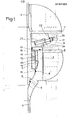
- the tubular elements (3, 4) comprise flanges (7, 8) for fixing to the lower part and to the upper part of the extension tube, peripheral lines 9 which are fitted in a completely conventional manner to said tubes.
- the female tubular element 3 internally comprises a ring of tenons 12.
- a locking ring 13 provided at its lower part and externally with a ring of tenons 14.
- the upper face of the locking ring 13 has teeth 15 cooperating with teeth provided below a ring 16 which surrounds the male tubular element 4 and which bears on the edge of the female element 3.
- the connector also includes members 2, designated by the reference 20, uniformly distributed around the male tubular element 4 and ensuring the locking of said connector in the locked position.
- Each blocking member 20 is constituted by a screw 21 mounted freely in rotation on a sole 22 fixed below the flange 7.
- the sole 22 has an inclined face 23 and the screw 21 drives in translation a wedge wedge 24 which slides between the inclined face and the ring 16.
- the ring 16 is turned a fraction of a turn to drive in rotation, by means of the teeth 15, the ring 13 so that the studs 14 are positioned below the studs 12.
- the blocking members 20, still being in place, the screws 21 are successively turned causing the biased shims 24 to move in translation in the direction indicated by the arrow 30 in FIG. 2.
- This translation applies, by the wedge effect of the bias wedges 24, on the one hand an axial thrust directed downward on the female tubular element 3 via the ring 16 and on the other hand an axial thrust directed upwards on the male tubular element 4 via the flanges 22 and the flange 7.
- the ring 13 is wedged in the groove 10 between the two tubular elements (3, 4) and immobilized in this locking position by the crowns of tenons (12, 14). The coupling is therefore locked.
- the release will be carried out by loosening the bias wedges 24 and uncoupling by rotation of a fraction d p turn of the ring 13.
- This arrangement allows a minimum of machining operations of the various elements and forms a compact assembly in which the rotating locking ring is well protected between two solid parts, which makes it possible to reduce the dimensions of the ring and consequently the dimensions of the fitting, while allowing easy access to the seals. Furthermore, it also allows a good distribution of the load around the circumference of the tubular elements, and very easily control the areas with high stress.
Landscapes
- Engineering & Computer Science (AREA)
- Geology (AREA)
- Life Sciences & Earth Sciences (AREA)
- Mining & Mineral Resources (AREA)
- Physics & Mathematics (AREA)
- Environmental & Geological Engineering (AREA)
- Fluid Mechanics (AREA)
- Mechanical Engineering (AREA)
- General Life Sciences & Earth Sciences (AREA)
- Geochemistry & Mineralogy (AREA)
- Earth Drilling (AREA)
- Quick-Acting Or Multi-Walled Pipe Joints (AREA)
- Lubricants (AREA)
- Fats And Perfumes (AREA)
Priority Applications (1)
| Application Number | Priority Date | Filing Date | Title |
|---|---|---|---|
| AT84402690T ATE27333T1 (de) | 1983-12-23 | 1984-12-21 | Schnellkupplung fuer standrohre von oelbohrungen. |
Applications Claiming Priority (2)
| Application Number | Priority Date | Filing Date | Title |
|---|---|---|---|
| FR8320675A FR2557194B1 (fr) | 1983-12-23 | 1983-12-23 | Raccord rapide pour tube prolongateur de forage petrolier |
| FR8320675 | 1983-12-23 |
Publications (2)
| Publication Number | Publication Date |
|---|---|
| EP0147321A1 true EP0147321A1 (de) | 1985-07-03 |
| EP0147321B1 EP0147321B1 (de) | 1987-05-20 |
Family
ID=9295495
Family Applications (1)
| Application Number | Title | Priority Date | Filing Date |
|---|---|---|---|
| EP84402690A Expired EP0147321B1 (de) | 1983-12-23 | 1984-12-21 | Schnellkupplung für Standrohre von Ölbohrungen |
Country Status (6)
| Country | Link |
|---|---|
| US (1) | US4652021A (de) |
| EP (1) | EP0147321B1 (de) |
| AT (1) | ATE27333T1 (de) |
| DE (1) | DE3463809D1 (de) |
| FR (1) | FR2557194B1 (de) |
| NO (1) | NO164190C (de) |
Cited By (2)
| Publication number | Priority date | Publication date | Assignee | Title |
|---|---|---|---|---|
| FR2784417A1 (fr) | 1998-10-13 | 2000-04-14 | Inst Francais Du Petrole | Methode et dispositif de reglage de la flottabilite d'une colonne montante de forage sous-marin |
| FR2799789A1 (fr) | 1999-09-24 | 2001-04-20 | Inst Francais Du Petrole | Element de riser avec conduites auxiliaires integres |
Families Citing this family (12)
| Publication number | Priority date | Publication date | Assignee | Title |
|---|---|---|---|---|
| DE19647073C1 (de) * | 1996-11-14 | 1998-04-02 | Festo Ag & Co | Wartungsgerät zur Druckluftaufbereitung |
| DE19728779C2 (de) * | 1997-07-05 | 1999-09-09 | Ghh Borsig Turbomaschinen Gmbh | Verbindung für horizontal geteilte Gehäuse von Turbomaschinen |
| DE10159667A1 (de) * | 2001-12-05 | 2003-06-18 | Rolls Royce Deutschland | Verbindungsvorrichtung |
| FR2925105B1 (fr) | 2007-12-18 | 2010-01-15 | Inst Francais Du Petrole | Troncon de colonne montante avec des conduites auxiliaires bridees et des connexions a baionnette. |
| FR2928958B1 (fr) * | 2008-03-19 | 2010-03-05 | Inst Francais Du Petrole | Systeme de forage et d'exploitation comportant une colonne montante avec un connecteur pre-tendu en tete |
| US9046204B2 (en) * | 2009-04-28 | 2015-06-02 | Baker Hughes Incorporated | Quick connect tool with locking collar |
| FR2950650B1 (fr) | 2009-09-28 | 2013-11-22 | Inst Francais Du Petrole | Colonne montante avec conduites auxiliaires rigides assemblees par des broches |
| FR2950924B1 (fr) | 2009-10-07 | 2011-10-28 | Inst Francais Du Petrole | Colonne montante avec conduites auxiliaires rigides et connecteurs decales |
| US10738541B2 (en) * | 2018-02-02 | 2020-08-11 | Hydril USA Distribution LLC | System and method for threaded riser auxiliary lines |
| US11555564B2 (en) | 2019-03-29 | 2023-01-17 | Baker Hughes Oilfield Operations Llc | System and method for auxiliary line connections |
| ES2989660T3 (es) * | 2020-08-31 | 2024-11-27 | Sulzer Management Ag | Bomba para bombear un fluido |
| US12196045B2 (en) * | 2022-02-22 | 2025-01-14 | Seahorse Technologies, Inc. | Connection assembly |
Citations (6)
| Publication number | Priority date | Publication date | Assignee | Title |
|---|---|---|---|---|
| FR961165A (de) * | 1950-05-06 | |||
| FR1205294A (fr) * | 1957-04-03 | 1960-02-02 | Stamicarbon | Perfectionnements aux accouplements pour tubes de sonde |
| US3848421A (en) * | 1971-03-08 | 1974-11-19 | Brien B O | Riser section apparatus |
| US4043575A (en) * | 1975-11-03 | 1977-08-23 | The Rucker Company | Riser connector |
| FR2376990A1 (fr) * | 1977-01-10 | 1978-08-04 | Fmc Corp | Mecanisme de raccordement pour conduites a force elevee |
| FR2512877A1 (fr) * | 1981-09-03 | 1983-03-18 | Orszagos Koolaj Gazipari | Equipement de liaison pour forage et exploitation de puits de petrole et de gaz naturel |
Family Cites Families (6)
| Publication number | Priority date | Publication date | Assignee | Title |
|---|---|---|---|---|
| US3472538A (en) * | 1968-02-28 | 1969-10-14 | Pan American Petroleum Corp | Joint for coupling two tubular members together |
| US4068865A (en) * | 1975-12-29 | 1978-01-17 | Vetco Offshore, Inc. | Pipe connectors |
| US4330140A (en) * | 1977-04-01 | 1982-05-18 | Smith International, Inc. | Marine riser connector |
| FR2526517B2 (fr) * | 1978-08-03 | 1986-05-02 | Inst Francais Du Petrole | Connecteur a anneau tournant, en particulier pour colonne montante utilisee dans l'exploration ou la production petroliere en mer |
| FR2432672A1 (fr) * | 1978-08-03 | 1980-02-29 | Inst Francais Du Petrole | Connecteur a anneau tournant, en particulier pour colonne montante utilisee dans l'exploration ou la production petroliere en mer |
| US4278278A (en) * | 1979-08-30 | 1981-07-14 | W-K-M Wellhead Systems, Inc. | Means for tensioning tubing in a wellhead assembly |
-
1983
- 1983-12-23 FR FR8320675A patent/FR2557194B1/fr not_active Expired
-
1984
- 1984-11-26 NO NO844694A patent/NO164190C/no not_active IP Right Cessation
- 1984-12-21 EP EP84402690A patent/EP0147321B1/de not_active Expired
- 1984-12-21 DE DE8484402690T patent/DE3463809D1/de not_active Expired
- 1984-12-21 US US06/685,178 patent/US4652021A/en not_active Expired - Lifetime
- 1984-12-21 AT AT84402690T patent/ATE27333T1/de not_active IP Right Cessation
Patent Citations (6)
| Publication number | Priority date | Publication date | Assignee | Title |
|---|---|---|---|---|
| FR961165A (de) * | 1950-05-06 | |||
| FR1205294A (fr) * | 1957-04-03 | 1960-02-02 | Stamicarbon | Perfectionnements aux accouplements pour tubes de sonde |
| US3848421A (en) * | 1971-03-08 | 1974-11-19 | Brien B O | Riser section apparatus |
| US4043575A (en) * | 1975-11-03 | 1977-08-23 | The Rucker Company | Riser connector |
| FR2376990A1 (fr) * | 1977-01-10 | 1978-08-04 | Fmc Corp | Mecanisme de raccordement pour conduites a force elevee |
| FR2512877A1 (fr) * | 1981-09-03 | 1983-03-18 | Orszagos Koolaj Gazipari | Equipement de liaison pour forage et exploitation de puits de petrole et de gaz naturel |
Cited By (3)
| Publication number | Priority date | Publication date | Assignee | Title |
|---|---|---|---|---|
| FR2784417A1 (fr) | 1998-10-13 | 2000-04-14 | Inst Francais Du Petrole | Methode et dispositif de reglage de la flottabilite d'une colonne montante de forage sous-marin |
| FR2799789A1 (fr) | 1999-09-24 | 2001-04-20 | Inst Francais Du Petrole | Element de riser avec conduites auxiliaires integres |
| US6623044B1 (en) | 1999-09-24 | 2003-09-23 | Institut Francais Du Petrole | Riser element with integrated auxiliary pipes |
Also Published As
| Publication number | Publication date |
|---|---|
| EP0147321B1 (de) | 1987-05-20 |
| FR2557194B1 (fr) | 1986-05-16 |
| FR2557194A1 (fr) | 1985-06-28 |
| ATE27333T1 (de) | 1987-06-15 |
| NO164190B (no) | 1990-05-28 |
| US4652021A (en) | 1987-03-24 |
| NO164190C (no) | 1990-09-05 |
| NO844694L (no) | 1985-06-24 |
| DE3463809D1 (en) | 1987-06-25 |
Similar Documents
| Publication | Publication Date | Title |
|---|---|---|
| EP0147321B1 (de) | Schnellkupplung für Standrohre von Ölbohrungen | |
| CA1217733A (fr) | Ensemble et methode permettant de realiser au moins une liaison electrique entre deux points a travers une conduite | |
| FR2508970A1 (fr) | Ensemble a raccord, appareil de raccordement, joint de tubes et procede de realisation d'un raccord visse entre deux elements longitudinaux | |
| FR2490717A1 (fr) | Appareil pour realiser entre deux conduites un joint annulaire pouvant etre utilise comme packer dans un trou de forage | |
| FR2507281A1 (fr) | Appareil et procede pour raccorder des elements tubulaires | |
| FR2507241A1 (fr) | Appareil destine a etre place dans une conduite de puits pour realiser une obturation entre cette conduite et un element dispose a l'interieur de ladite conduite | |
| FR2545148A1 (fr) | Ensemble d'accouplements pour tube prolongateur | |
| FR2666114A1 (fr) | Outil de fond de puits et procede de transmission selective de fluides entre l'interieur et l'exterieur d'un tel outil. | |
| FR2567616A1 (fr) | Ensemble a raccord, appareil de raccordement, joint de tubes et procede de realisation d'un raccord visse entre deux elements longitudinaux | |
| FR2566059A1 (fr) | Pompe a cavite progressant a travers des tubes | |
| FR2528144A1 (fr) | Dispositif d'etancheite pour robinet a tournant spherique | |
| FR2514097A1 (fr) | Joint tournant pour relier entre eux deux conduits | |
| EP2225432A2 (de) | Steigrohrelement mit angeflanschten hilfskanälen und bajonettverbindungen | |
| EP0044231B1 (de) | Elastische Rohrverbindung | |
| FR2767153A1 (fr) | Dispositif et procede de centrage d'un outil dans un conduit notamment dans une tige de forage | |
| FR2514439A1 (fr) | Rotule pour pied de colonne montante | |
| FR2552843A3 (fr) | Valve a boule munie d'une bague de blocage | |
| FR2542366A1 (fr) | Appareil pour le forage dirige de puits souterrains | |
| FR2497917A1 (fr) | Dispositif de verrouillage pouvant etre deverrouille | |
| FR2521095A1 (fr) | Caisson de travail pour installations en mer | |
| FR2560656A1 (fr) | Joint a assemblage a distance | |
| EP0294252B1 (de) | Ausrüstung für einen Bohrstrang mit einem Zwischenstück mit einer seitlichen Öffnung und Verfahren für deren Anwendung | |
| CA1261311A (fr) | Dispositif d'obturation pour conduite vehiculant un fluide | |
| EP0456538B1 (de) | Dichtungssystem einer Antriebswelle mit inneren Rinnen | |
| FR2521634A1 (fr) | Siege et appareil pour supporter plusieurs dispositifs de suspension de colonne dans une tete de puits, ensemble a joint, appareil pour actionner un joint en elastomere et a contact metal sur metal, outil pour actionner un ensemble d'obturation et de retenue, outil pour descendre un dispositif de suspension dans une tete de puits sous-marin, ensemble d'obturation et de retenue, dispositif de suspension d'une colonne, appareil pour l'obturation et le verrouillage d'un dispositif de suspension dans u |
Legal Events
| Date | Code | Title | Description |
|---|---|---|---|
| PUAI | Public reference made under article 153(3) epc to a published international application that has entered the european phase |
Free format text: ORIGINAL CODE: 0009012 |
|
| AK | Designated contracting states |
Designated state(s): AT BE CH DE FR GB IT LI LU NL SE |
|
| RTI1 | Title (correction) | ||
| 17P | Request for examination filed |
Effective date: 19850531 |
|
| 17Q | First examination report despatched |
Effective date: 19860806 |
|
| GRAA | (expected) grant |
Free format text: ORIGINAL CODE: 0009210 |
|
| AK | Designated contracting states |
Kind code of ref document: B1 Designated state(s): AT BE CH DE FR GB IT LI LU NL SE |
|
| PG25 | Lapsed in a contracting state [announced via postgrant information from national office to epo] |
Ref country code: AT Effective date: 19870520 |
|
| REF | Corresponds to: |
Ref document number: 27333 Country of ref document: AT Date of ref document: 19870615 Kind code of ref document: T |
|
| ITF | It: translation for a ep patent filed | ||
| REF | Corresponds to: |
Ref document number: 3463809 Country of ref document: DE Date of ref document: 19870625 |
|
| PG25 | Lapsed in a contracting state [announced via postgrant information from national office to epo] |
Ref country code: LU Free format text: LAPSE BECAUSE OF NON-PAYMENT OF DUE FEES Effective date: 19871231 Ref country code: LI Effective date: 19871231 Ref country code: CH Effective date: 19871231 |
|
| PLBE | No opposition filed within time limit |
Free format text: ORIGINAL CODE: 0009261 |
|
| STAA | Information on the status of an ep patent application or granted ep patent |
Free format text: STATUS: NO OPPOSITION FILED WITHIN TIME LIMIT |
|
| 26N | No opposition filed | ||
| REG | Reference to a national code |
Ref country code: CH Ref legal event code: PL |
|
| REG | Reference to a national code |
Ref country code: CH Ref legal event code: AUV Free format text: TOMBE EN DECHEANCE 26.07.88 FAUTE DE PAIEMENT, DE LA 4E ANNUITE. |
|
| ITTA | It: last paid annual fee | ||
| EAL | Se: european patent in force in sweden |
Ref document number: 84402690.6 |
|
| REG | Reference to a national code |
Ref country code: FR Ref legal event code: TP |
|
| REG | Reference to a national code |
Ref country code: GB Ref legal event code: 732E |
|
| NLS | Nl: assignments of ep-patents |
Owner name: INSTITUT FRANCAIS DU PETROLE;FRAMATOME, SOCIETE AN |
|
| BECA | Be: change of holder's address |
Free format text: 20010319 INSTITUT FRANCAIS DU *PETROLE(ORGANISME PROFESSIONEL):1 & 4 AVENUE DE BOIS PREAU, 92852 RUEIL MALMAISON CEDEX |
|
| BECH | Be: change of holder |
Free format text: 20010319 INSTITUT FRANCAIS DU *PETROLE(ORGANISME PROFESSIONEL):1 & 4 AVENUE DE BOIS PREAU, 92852 RUEIL MALMAISON CEDEX |
|
| REG | Reference to a national code |
Ref country code: GB Ref legal event code: IF02 |
|
| PGFP | Annual fee paid to national office [announced via postgrant information from national office to epo] |
Ref country code: FR Payment date: 20031015 Year of fee payment: 20 |
|
| PGFP | Annual fee paid to national office [announced via postgrant information from national office to epo] |
Ref country code: GB Payment date: 20031124 Year of fee payment: 20 |
|
| PGFP | Annual fee paid to national office [announced via postgrant information from national office to epo] |
Ref country code: SE Payment date: 20031222 Year of fee payment: 20 Ref country code: BE Payment date: 20031222 Year of fee payment: 20 |
|
| PGFP | Annual fee paid to national office [announced via postgrant information from national office to epo] |
Ref country code: NL Payment date: 20031223 Year of fee payment: 20 |
|
| PGFP | Annual fee paid to national office [announced via postgrant information from national office to epo] |
Ref country code: DE Payment date: 20040112 Year of fee payment: 20 |
|
| PG25 | Lapsed in a contracting state [announced via postgrant information from national office to epo] |
Ref country code: GB Free format text: LAPSE BECAUSE OF EXPIRATION OF PROTECTION Effective date: 20041220 |
|
| PG25 | Lapsed in a contracting state [announced via postgrant information from national office to epo] |
Ref country code: NL Free format text: LAPSE BECAUSE OF EXPIRATION OF PROTECTION Effective date: 20041221 |
|
| BE20 | Be: patent expired |
Owner name: INSTITUT FRANCAIS DU *PETROLE(ORGANISME PROFESSION Effective date: 20041221 |
|
| REG | Reference to a national code |
Ref country code: GB Ref legal event code: PE20 |
|
| EUG | Se: european patent has lapsed | ||
| NLV7 | Nl: ceased due to reaching the maximum lifetime of a patent |
Effective date: 20041221 |
|
| EUG | Se: european patent has lapsed |