EP0146963A2 - Iir digital filter - Google Patents
Iir digital filter Download PDFInfo
- Publication number
- EP0146963A2 EP0146963A2 EP84116288A EP84116288A EP0146963A2 EP 0146963 A2 EP0146963 A2 EP 0146963A2 EP 84116288 A EP84116288 A EP 84116288A EP 84116288 A EP84116288 A EP 84116288A EP 0146963 A2 EP0146963 A2 EP 0146963A2
- Authority
- EP
- European Patent Office
- Prior art keywords
- adder
- circuit
- output
- delay circuit
- denominator
- Prior art date
- Legal status (The legal status is an assumption and is not a legal conclusion. Google has not performed a legal analysis and makes no representation as to the accuracy of the status listed.)
- Granted
Links
Images
Classifications
-
- H—ELECTRICITY
- H03—ELECTRONIC CIRCUITRY
- H03H—IMPEDANCE NETWORKS, e.g. RESONANT CIRCUITS; RESONATORS
- H03H17/00—Networks using digital techniques
- H03H17/02—Frequency selective networks
- H03H17/04—Recursive filters
Definitions
- the present invention relates to an IIR digital filter applied to color video signals.
- An IIR digital filter is a filter having sharp characteristics at lower order.
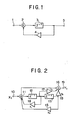
- the IIR digital filter has a feedback constitution as shown in Fig. 1.
- present input signal is supplied from an input terminal designated by numeral 1 to one input terminal of an adder 2, and past output signal stored in a unit delay circuit 3 is multiplied by coefficient in a multiplying circuit 4 and then supplied to other input terminal of the adder 2, thereby output of the adder 2 is taken through the unit delay circuit 3 to an output terminal 5.
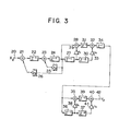
- system function H(Z) is expressed by an IIR digital filter of second order corresponding to the H(Z) is constituted as shown in Fig. 2.
- Fig. 2 input signal x 1 from an input terminal 10 is supplied to an adder 11. Adding output of the adder 11 is supplied to a unit delay circuit 12, and output of the unit delay circuit 12 is supplied to another unit delay circuit 13. The output of the unit delay circuit 12 is multiplied by a multiplying circuit 14 of coefficient b l and supplied to the adder 11. Output of the unit delay circuit 13 is multiplied by a multiplying circuit 15 of coefficient b 2 and supplied to the adder 11.
- Output of the adder 11 is supplied to another adder 16, and the output of the unit delay circuit 12 and the output of the unit delay circuit 13 are multiplied by a multiplying circuit 17 of coefficient a 1 and a multiplying circuit 18 of coefficient a 2 respectively, and then both multiplying outputs are supplied to the adder 16.
- Output of the adder 16 is supplied to an output terminal 19, and output signal Y 1 is taken from the output terminal 19.
- the IIR digital filter has feedback constitution including the multiplying circuits 14 and 15. This constitution corresponds to polynomial in denominator of expression (1).
- an object of the invention is to provide an IIR digital filter which can be applied to processing of color video signal or the like and use an operation element of low speed and small power, such as CMOS.
- the invention is in an IIR digital filter wherein the same polynomial is multiplied to both denominator and numerator of system function of the IIR digital filter, thereby at least Z -1 term is eliminated among terns in the denominator of the system function and pipeline processing is applied to product/sum operation composed of coefficient multiplication and addition in the system function after transformation.
- the system function of secod- order section of the IIR digital filter as shown in above expression (1) is where the denominator includes Z -1 term.
- Terms in the denominator become feedback constitution as above described. Particularly, term including Z -1 in the denominator must be processed by multiplication and addition in one clock and therefore pipeline processing cannot be executed.
- the same polynomial is multiplied to both the denominator and the numerator.
- the system function H(Z) shown in expression (2) the term including Z -1 is eliminated from the denominator. Consequently, product/sum operation to be executed in one clock may be done during two clocks. This enables application of the pipeline processing to the product/sum operation as shown in Fig. 3.
- Fig. 3 shows an IIR digital filter on the basis of expression (2), and numeral 20 in Fig. 3 designates an input terminal.
- Color video signal Z 2x digitized by sampling pulse of 4f sc for example, is supplied from the input terminal 20 to an adder 21.
- Adding output of the adder 21 is supplied to a unit delay circuit 22, and output of the unit delay circuit 22 is supplied to an adder 23, and further adding output of the adder 23 is supplied to a unit delay circuit 24.
- Output of the unit delay circuit 24 is supplied to a multiplying circuit 25 in pipeline processing and also to a multiplying circuit 26 in pipeline processing.
- the adders 21, 23, the unit delay circuit 22, 24 and the multiplying circuits 25, 26 together execute processing corresponding to the polynomial shown in the denominator of expression (2).
- Output of the unit delay circuit 24 is supplied to a unit-delay circuit 27 and an adder 28.
- Output of the unit delay circuit 27 is supplied to a multiplying circuit 29 and also to a delay circuit 30 having delay amount twice as large as the unit delay amount.
- the multiplying circuit 29 is one having coefficient a Output of the multiplying circuit 29 is supplied to the adder 28, and adding output of the adder 28 is supplied to a unit delay circuit 31, and further output of the unit delay circuit 31 is supplied to an adder 32.
- Output of the delay circuit 30 is supplied to a multiplier circuit 33.
- the multiplying circuit 33 is one having coefficient a 2 , and multiplying output of the multiplying circuit 33 is supplied to the adder 32. Adding output of the adder 32 is supplied to a unit delay circuit 34.
- the adders 28, 32, the delay circuits 27, 30, 31, 34 and the multiplying circuits 29, 33 together execute processing corresponding to the polynomial of second order representing the factor in the numerator of expression (2).
- Output of the unit delay circuit 34 is supplied to an adder 35 and a unit delay circuit 36.
- Output of the unit delay circuit 36 is supplied to a delay circuit 37 having delay amount twice as large as the unit delay amount and also to a multiplying circuit 38.
- the multiplying circuit 38 is one having coefficient b l .
- Multiplying output of the multiplying circuit 38 is supplied to the adder 35, and adding output of the adder 35 is supplied to a unit delay circuit 39, and further output of the unit delay circuit 39 is supplied to an adder 40.
- Output of the delay circuit 37 is supplied to a multiplying circuit 41.
- the multiplying circuit 41 is one having coefficient -bl, and output of the multiplying circuit 41 is supplied to the adder 40.
- the adders 35, 40, the delay circuits 36, 37, 39 and the multiplying circuits 38, 41 together execute processing corresponding to the polynomial of second order representing the factor in the numerator of expression (2).
- Output of the adder 40 is taken as output signal Y 2 from an output terminal 42.
- System function in any order of an IIR digital filter can be subjected to factorization into product of system function of second order and system function of first order. Consequently, an IIR digital filter of any order can be implemented by cascade connection of a number of IIR digital filters as shown in Fig. 3.
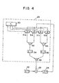
- Fig. 4 shows an example of multiplying circuit 25 in pipeline processing to be used in the embodiment of Fig. 3.
- coefficient i.e. digital signal K 1 of multiplier is input of four bits and the signal K 1 is multiplied to a delay circuit 24.
- output of the unit delay circuit 24 is supplied to selectors 51a - 51d and selected by each bit signal of multiplier K 1 supplied to each selector. for example,when the multiplier K 1 is 1001, the selectors 51a, 51d are turned on and partial product signal is taken at output side thereof, and output of the selector 51a is shifted by one bit to the left and supplied to an adder 52. Output of the selector 51d is supplied to an adder 53.
- the multiplier K 1 is four bits and the number of adding steps may be relatively small. However, it is clear that if the multiplier K 1 is eight bits or more the number of adding steps increases and effect of pipeline processing further increases.
- an encoder using Booth algorithm may be used to form the partial product.
- the delay circuit of one step among the unit delay circuits 54, 55 will do, but the pipeline processing of two steps is necessary in the multiplying circuit 26.
- a unit delay circuit of further step may be inserted between the adder 56 and the adder 23 in Fig. 4. In this constitution, the operation cycle time can be made 1/3.
- processing corresponding to the denominator of the system function is previously executed and then processing corresponding to the numerator is executed.
- processing corresponding to the numerator may be previously done and then processing corresponding to the denominator be done.
- the numerator is constituted as product of polynomial of second order in the embodiment, polynomial of the numerator may be expanded into polynomial of fourth order.
- an adder of two- input type is only used.
- output of the delay circuit 22 may be connected to input of the delay circuit 24 and be fed back from the joint of these delay circuits 22, 24 through the multiplying circuit 25 in pipeline processing to other input terminal of the adder 21 at input side of the delay circuit 22.
- a separate FIR filter need not be constituted in series to the circuit constituting the IIR filter, but the delay circuits 22, 24 to constitute the IIR filter may be also used as an FIR filter.
- pipeline processing of one step and two steps may be applied to the multiplying circuits 25 and 26 in the feedback loop. If the pipeline processing of one step is executed, the operation stage is divided into two steps and the operation cycle time can be made 1/2. -Likewise, if the pipeline processing of n steps is executed, the operation stage is divided- into (n+l) steps and the cycle time can be made l/(n+l). since the system function H(Z) is transformed, the multiplying circuits 25 and 26 in the feedback loop have double word length in comparison to the multiplying circuits 14 and 15 in the feedback loop before the transformation of the system function H(Z).
Abstract
Description
- The present invention relates to an IIR digital filter applied to color video signals.
- An IIR digital filter is a filter having sharp characteristics at lower order. The IIR digital filter has a feedback constitution as shown in Fig. 1. As clearly seen from Fig. 1, present input signal is supplied from an input terminal designated by
numeral 1 to one input terminal of anadder 2, and past output signal stored in aunit delay circuit 3 is multiplied by coefficient in amultiplying circuit 4 and then supplied to other input terminal of theadder 2, thereby output of theadder 2 is taken through theunit delay circuit 3 to anoutput terminal 5. - For example, if system function H(Z) is expressed by

- In Fig. 2, input signal x1 from an
input terminal 10 is supplied to anadder 11. Adding output of theadder 11 is supplied to aunit delay circuit 12, and output of theunit delay circuit 12 is supplied to anotherunit delay circuit 13. The output of theunit delay circuit 12 is multiplied by amultiplying circuit 14 of coefficient bl and supplied to theadder 11. Output of theunit delay circuit 13 is multiplied by a multiplyingcircuit 15 of coefficient b2 and supplied to theadder 11. Output of theadder 11 is supplied to anotheradder 16, and the output of theunit delay circuit 12 and the output of theunit delay circuit 13 are multiplied by amultiplying circuit 17 of coefficient a1 and amultiplying circuit 18 of coefficient a2 respectively, and then both multiplying outputs are supplied to theadder 16. Output of theadder 16 is supplied to anoutput terminal 19, and output signal Y1 is taken from theoutput terminal 19. - As shown in Fig. 2, the IIR digital filter has feedback constitution including the
multiplying circuits - For example, when color video signal is digitized by sampling pulse of 4f sc (f sc color subscriber frequency), one sampling clock is 70 n sec. If the color video signal is processed using the IIR digital filter shown in Fig. 2, term b1Z-1 including Z-1 in the denominator must be processed by product/sum operation composed of multiplication and addition in a. short time of 70 n sec. Since this processing..requires time particularly for the multiplication, operation element of low speed and small consumption power, such as CMOS, cannot be used, but that of high speed and large consumption power, such as bipolar element or ECL element, can only be used.
- Accordingly, an object of the invention is to provide an IIR digital filter which can be applied to processing of color video signal or the like and use an operation element of low speed and small power, such as CMOS.
- The invention is in an IIR digital filter wherein the same polynomial is multiplied to both denominator and numerator of system function of the IIR digital filter, thereby at least Z-1 term is eliminated among terns in the denominator of the system function and pipeline processing is applied to product/sum operation composed of coefficient multiplication and addition in the system function after transformation.
-
- Fig. 1 is a block diagram illustrating feedback constitution required for an IIR digital filter;
- Fig. 2 is a block diagram of an IIR digital filter as an example in the prior art;
- Fig. 3 is a block diagram of an embodiment of the invention; and
- Fig. 4 is a block diagram of an example of a
multiplying circuit 25 in pipeline processing. - An embodiment of the invention will now be described referring to the accompanying drawings.
- For example, the system function of secod- order section of the IIR digital filter as shown in above expression (1) is


- Fig. 3 shows an IIR digital filter on the basis of expression (2), and
numeral 20 in Fig. 3 designates an input terminal. Color video signal Z2x digitized by sampling pulse of 4fsc, for example, is supplied from theinput terminal 20 to anadder 21. Adding output of theadder 21 is supplied to aunit delay circuit 22, and output of theunit delay circuit 22 is supplied to anadder 23, and further adding output of theadder 23 is supplied to aunit delay circuit 24. Output of theunit delay circuit 24 is supplied to a multiplyingcircuit 25 in pipeline processing and also to a multiplyingcircuit 26 in pipeline processing. The multiplyingcircuit 25 is one having coefficient (K1 = 2b2 + b1 2), and pipeline processing in one step is executed using a register for example. The multiplyingcircuit 26 is one having coefficient (K2 = -b2 2), and pipeline processing in two steps is-executed using a register for example. Multiplying output of themultiplying circuit 25 is supplied to theadder 23, and multiplying output of themultiplying circuit 26 is supplied to theadder 21. - The
adders unit delay circuit multiplying circuits 
- Output of the
unit delay circuit 24 is supplied to a unit-delay circuit 27 and anadder 28. Output of theunit delay circuit 27 is supplied to a multiplyingcircuit 29 and also to adelay circuit 30 having delay amount twice as large as the unit delay amount. Themultiplying circuit 29 is one having coefficient a Output of the multiplyingcircuit 29 is supplied to theadder 28, and adding output of theadder 28 is supplied to a unit delay circuit 31, and further output of the unit delay circuit 31 is supplied to an adder 32. Output of thedelay circuit 30 is supplied to amultiplier circuit 33. Themultiplying circuit 33 is one having coefficient a2, and multiplying output of themultiplying circuit 33 is supplied to the adder 32. Adding output of the adder 32 is supplied to a unit delay circuit 34. - The
adders 28, 32, thedelay circuits multiplying circuits 
- Output of the unit delay circuit 34 is supplied to an
adder 35 and aunit delay circuit 36. Output of theunit delay circuit 36 is supplied to adelay circuit 37 having delay amount twice as large as the unit delay amount and also to a multiplyingcircuit 38. The multiplyingcircuit 38 is one having coefficient bl. Multiplying output of themultiplying circuit 38 is supplied to theadder 35, and adding output of theadder 35 is supplied to aunit delay circuit 39, and further output of theunit delay circuit 39 is supplied to anadder 40. Output of thedelay circuit 37 is supplied to a multiplyingcircuit 41. Themultiplying circuit 41 is one having coefficient -bl, and output of themultiplying circuit 41 is supplied to theadder 40. - The
adders delay circuits multiplying circuits 
- Output of the
adder 40 is taken as output signal Y2 from anoutput terminal 42. - System function in any order of an IIR digital filter can be subjected to factorization into product of system function of second order and system function of first order. Consequently, an IIR digital filter of any order can be implemented by cascade connection of a number of IIR digital filters as shown in Fig. 3.
- Fig. 4 shows an example of multiplying
circuit 25 in pipeline processing to be used in the embodiment of Fig. 3. In the example, coefficient, i.e. digital signal K1 of multiplier is input of four bits and the signal K1 is multiplied to adelay circuit 24. In the example of Fig. 4, output of theunit delay circuit 24 is supplied toselectors 51a - 51d and selected by each bit signal of multiplier K1 supplied to each selector. for example,when the multiplier K1 is 1001, theselectors selector 51a is shifted by one bit to the left and supplied to anadder 52. Output of theselector 51d is supplied to anadder 53. In usual multiplying circuit, output of theadder 52 is shifted by two bits to the left and added to anadder 56 thereby multiplying output is obtained from outputs of theadders unit delay circuits adders unit delay circuits selectors 51a - 51d and adding operation by theadders adder 56 and theadder 23 to add output of theadder 56 and output of thedelay circuit 22 may be performed during other one sample period, thereby the operation cycle time can be made.1/2. Although an adder of tree form is used for adding the partial product in the example, other adding system may be used. Also in the example, the multiplier K1 is four bits and the number of adding steps may be relatively small. However, it is clear that if the multiplier K1 is eight bits or more the number of adding steps increases and effect of pipeline processing further increases. Although an example of usual parallel multiplying circuit is disclosed in Fig. 4, an encoder using Booth algorithm may be used to form the partial product. - In the multiplying
circuit 25, since pipeline processing of one step is executed the delay circuit of one step among theunit delay circuits circuit 26. In this case, a unit delay circuit of further step may be inserted between theadder 56 and theadder 23 in Fig. 4. In this constitution, the operation cycle time can be made 1/3. - Comparing the embodiment of the invention with the IIR digital filter shown in Fig. 2, the fixed delay is increased by five steps in the embodiment thereby strictly saying the system function becomes multiplication of z-5 term to expression (2). However, both are equivalent in the essential characteristics and increase of the fixed delay produces no particular problem in processing of color video signal.
- In the embodiment of the invention, processing corresponding to the denominator of the system function is previously executed and then processing corresponding to the numerator is executed. However, processing corresponding to the numerator may be previously done and then processing corresponding to the denominator be done. Although the numerator is constituted as product of polynomial of second order in the embodiment, polynomial of the numerator may be expanded into polynomial of fourth order.
- In the embodiment of Fig. 3, an adder of two- input type is only used. However, if an adder of three- input type is used as shown in Fig. 2, output of the
delay circuit 22 may be connected to input of thedelay circuit 24 and be fed back from the joint of thesedelay circuits circuit 25 in pipeline processing to other input terminal of theadder 21 at input side of thedelay circuit 22. In this case, a separate FIR filter need not be constituted in series to the circuit constituting the IIR filter, but thedelay circuits - According to the invention, since the system function H(Z) is transformed and Z term is eliminated from the denominator, pipeline processing of one step and two steps may be applied to the multiplying
circuits circuits circuits
Claims (3)


Applications Claiming Priority (2)
| Application Number | Priority Date | Filing Date | Title |
|---|---|---|---|
| JP243488/83 | 1983-12-23 | ||
| JP58243488A JPH0834408B2 (en) | 1983-12-23 | 1983-12-23 | IIR Digital Filter |
Publications (3)
| Publication Number | Publication Date |
|---|---|
| EP0146963A2 true EP0146963A2 (en) | 1985-07-03 |
| EP0146963A3 EP0146963A3 (en) | 1988-03-16 |
| EP0146963B1 EP0146963B1 (en) | 1992-09-23 |
Family
ID=17104631
Family Applications (1)
| Application Number | Title | Priority Date | Filing Date |
|---|---|---|---|
| EP84116288A Expired EP0146963B1 (en) | 1983-12-23 | 1984-12-24 | Iir digital filter |
Country Status (4)
| Country | Link |
|---|---|
| US (1) | US4751663A (en) |
| EP (1) | EP0146963B1 (en) |
| JP (1) | JPH0834408B2 (en) |
| DE (1) | DE3485935T2 (en) |
Families Citing this family (22)
| Publication number | Priority date | Publication date | Assignee | Title |
|---|---|---|---|---|
| JPH0738565B2 (en) * | 1986-01-10 | 1995-04-26 | ソニー株式会社 | High speed digital filter |
| JPS63174721U (en) * | 1987-03-20 | 1988-11-14 | ||
| US4855944A (en) * | 1987-09-04 | 1989-08-08 | Rockwell International Corporation | Noise generator with shaped spectrum |
| JPH01248816A (en) * | 1988-03-30 | 1989-10-04 | Toshiba Corp | Digital filter |
| US5089981A (en) * | 1989-04-24 | 1992-02-18 | Audio Precision, Inc. | Hybrid form digital filter |
| US5181228A (en) * | 1990-10-12 | 1993-01-19 | Level One Communications, Inc. | System and method for phase equalization |
| US5226057A (en) * | 1991-03-20 | 1993-07-06 | Rockwell International Corporation | Receiver and adaptive digital notch filter |
| JPH0537299A (en) * | 1991-04-12 | 1993-02-12 | Sony Corp | Circular digital filter |
| US5402520A (en) * | 1992-03-06 | 1995-03-28 | Schnitta; Bonnie S. | Neural network method and apparatus for retrieving signals embedded in noise and analyzing the retrieved signals |
| US5297557A (en) * | 1992-10-14 | 1994-03-29 | Del Mar Avionics | Stress test system with bidirectional filter |
| US5553013A (en) * | 1994-09-30 | 1996-09-03 | Ford Motor Company | Delay generation filter |
| US5701099A (en) * | 1995-11-27 | 1997-12-23 | Level One Communications, Inc. | Transconductor-C filter element with coarse and fine adjustment |
| FR2742956B1 (en) * | 1995-12-22 | 1998-01-30 | Thomson Multimedia Sa | CIRCUIT FOR PERFORMING DIGITAL NYQUIST FILTERING OF INTERMEDIATE FREQUENCY SIGNALS |
| US5996004A (en) * | 1996-01-02 | 1999-11-30 | Bp Microsystems, Inc. | Concurrent programming apparatus and method for electronic devices |
| US5732003A (en) * | 1996-04-15 | 1998-03-24 | Boeing North American, Inc. | Sawtooth phase filter |
| US5905659A (en) * | 1997-10-07 | 1999-05-18 | Rose; Ralph E. | Training a recursive filter by use of derivative function |
| WO2009090138A1 (en) * | 2008-01-14 | 2009-07-23 | Elmos Semiconductor Ag | Method for distinguishing two signals |
| US10490459B2 (en) | 2017-08-25 | 2019-11-26 | Taiwan Semiconductor Manufacturing Co., Ltd. | Method for source/drain contact formation in semiconductor devices |
| US20120300960A1 (en) | 2011-05-27 | 2012-11-29 | Graeme Gordon Mackay | Digital signal routing circuit |
| US9660624B1 (en) * | 2014-03-21 | 2017-05-23 | Altera Corporation | Methods and apparatus for implementing feedback loops |
| WO2016029066A1 (en) | 2014-08-20 | 2016-02-25 | Wright State University | Fractional scaling digital signal processing |
| TWI635703B (en) * | 2017-01-03 | 2018-09-11 | 晨星半導體股份有限公司 | Notch filter and corresponding filter circuit capable of partially suppressing/attenuating signal frequency component |
Citations (1)
| Publication number | Priority date | Publication date | Assignee | Title |
|---|---|---|---|---|
| JPS5630316A (en) * | 1979-08-18 | 1981-03-26 | Fujitsu Ltd | Cyclic filter |
Family Cites Families (10)
| Publication number | Priority date | Publication date | Assignee | Title |
|---|---|---|---|---|
| GB197901A (en) * | 1922-05-19 | 1923-07-05 | L Avebene Soc | Improvements relating to fuel briquettes |
| US3619586A (en) * | 1968-11-25 | 1971-11-09 | Research Corp | Universal digital filter for linear discrete systems |
| FR2273419B1 (en) * | 1973-01-25 | 1976-09-10 | Trt Telecom Radio Electr | |
| US4021654A (en) * | 1975-06-11 | 1977-05-03 | Paradyne, Inc. | Digital filter |
| US4117541A (en) * | 1977-11-07 | 1978-09-26 | Communications Satellite Corporation | Configurable parallel arithmetic structure for recursive digital filtering |
| US4255794A (en) * | 1978-05-10 | 1981-03-10 | Nippon Electric Co., Ltd. | Digital filter |
| US4317092A (en) * | 1980-06-30 | 1982-02-23 | Hewlett-Packard Company | Recursive low pass digital filter |
| DE3121310A1 (en) * | 1981-05-29 | 1982-12-16 | Robert Bosch Gmbh, 7000 Stuttgart | DIGITAL FILTER |
| NL8201533A (en) * | 1982-04-13 | 1983-11-01 | Philips Nv | A TRANSMITTER DESIGNED FOR SENDING FM MODULATED SIGNALS. |
| EP0097753B1 (en) * | 1982-06-25 | 1986-10-01 | International Business Machines Corporation | Tone receiver for a digital data transmission system |
-
1983
- 1983-12-23 JP JP58243488A patent/JPH0834408B2/en not_active Expired - Lifetime
-
1984
- 1984-12-21 US US06/685,127 patent/US4751663A/en not_active Expired - Lifetime
- 1984-12-24 EP EP84116288A patent/EP0146963B1/en not_active Expired
- 1984-12-24 DE DE8484116288T patent/DE3485935T2/en not_active Expired - Fee Related
Patent Citations (1)
| Publication number | Priority date | Publication date | Assignee | Title |
|---|---|---|---|---|
| JPS5630316A (en) * | 1979-08-18 | 1981-03-26 | Fujitsu Ltd | Cyclic filter |
Non-Patent Citations (2)
| Title |
|---|
| 1978 IEEE INTERNATIONAL SYMPOSIUM ON CIRCUITS AND SYSTEMS PROCEEDINGS, 17th-19th May 1978, pages 752-756, IEEE, New York, US; E. LUEDER et al.: "Equivalent sampled data filter structures and some of their properties" * |
| PATENT ABSTRACTS OF JAPAN, vol. 5, no. 82 (E-59)[754], 29th May 1981; & JP-A-56 30 316 (FUJITSU K.K.) 26-03-1981 * |
Also Published As
| Publication number | Publication date |
|---|---|
| EP0146963A3 (en) | 1988-03-16 |
| US4751663A (en) | 1988-06-14 |
| EP0146963B1 (en) | 1992-09-23 |
| JPH0834408B2 (en) | 1996-03-29 |
| JPS60134619A (en) | 1985-07-17 |
| DE3485935D1 (en) | 1992-10-29 |
| DE3485935T2 (en) | 1993-02-11 |
Similar Documents
| Publication | Publication Date | Title |
|---|---|---|
| EP0146963A2 (en) | Iir digital filter | |
| US4791600A (en) | Digital pipelined heterodyne circuit | |
| US5586070A (en) | Structure and method for embedding two small multipliers in a larger multiplier | |
| GB2137839A (en) | Digital signal processors | |
| EP0101318B1 (en) | Digital filters | |
| KR100302093B1 (en) | How to multiply the binary input signal with the tap coefficient in the crossover digital finite impulse response filter and design the circuit arrangement and crossover digital filter | |
| GB1461477A (en) | Recursive digital filter | |
| US4366549A (en) | Multiplier with index transforms modulo a prime or modulo a fermat prime and the fermat prime less one | |
| He et al. | FPGA implementation of FIR filters using pipelined bit-serial canonical signed digit multipliers | |
| US5177703A (en) | Division circuit using higher radices | |
| US5798954A (en) | Digital filter device having a bit shifter unit | |
| WO1999019812A1 (en) | Reconfigurable infinite impulse response digital filter | |
| US8090013B2 (en) | Method and system of providing a high speed Tomlinson-Harashima Precoder | |
| US5928314A (en) | Digital filter having a substantially equal number of negative and positive weighting factors | |
| US5623434A (en) | Structure and method of using an arithmetic and logic unit for carry propagation stage of a multiplier | |
| US4716537A (en) | Circuit arrangement for simulating a resistive elementary two port device for use in a wave digital filter | |
| AU601489B2 (en) | A sampled data tone control system | |
| US5197020A (en) | Wave digital filter composed of delays and n-port adaptors | |
| Coleman | Cascaded coefficient number systems lead to FIR filters of striking computational efficiency | |
| JP2800820B2 (en) | Filter device | |
| US5561616A (en) | Fir filter based upon squaring | |
| US4984187A (en) | First order recursive digital filter without multiplier | |
| JP2880580B2 (en) | Acyclic digital filter circuit | |
| KR890004649Y1 (en) | Digital filter | |
| KR950010451B1 (en) | A flight speed multiplier using group tree structure algorithm |
Legal Events
| Date | Code | Title | Description |
|---|---|---|---|
| PUAI | Public reference made under article 153(3) epc to a published international application that has entered the european phase |
Free format text: ORIGINAL CODE: 0009012 |
|
| AK | Designated contracting states |
Designated state(s): AT BE CH DE FR GB IT LI LU NL SE |
|
| RBV | Designated contracting states (corrected) |
Designated state(s): DE FR GB NL |
|
| PUAL | Search report despatched |
Free format text: ORIGINAL CODE: 0009013 |
|
| AK | Designated contracting states |
Kind code of ref document: A3 Designated state(s): DE FR GB NL |
|
| 17P | Request for examination filed |
Effective date: 19880916 |
|
| 17Q | First examination report despatched |
Effective date: 19900927 |
|
| GRAA | (expected) grant |
Free format text: ORIGINAL CODE: 0009210 |
|
| AK | Designated contracting states |
Kind code of ref document: B1 Designated state(s): DE FR GB NL |
|
| REF | Corresponds to: |
Ref document number: 3485935 Country of ref document: DE Date of ref document: 19921029 |
|
| ET | Fr: translation filed | ||
| PLBE | No opposition filed within time limit |
Free format text: ORIGINAL CODE: 0009261 |
|
| STAA | Information on the status of an ep patent application or granted ep patent |
Free format text: STATUS: NO OPPOSITION FILED WITHIN TIME LIMIT |
|
| 26N | No opposition filed | ||
| PGFP | Annual fee paid to national office [announced via postgrant information from national office to epo] |
Ref country code: FR Payment date: 20011212 Year of fee payment: 18 |
|
| PGFP | Annual fee paid to national office [announced via postgrant information from national office to epo] |
Ref country code: GB Payment date: 20011227 Year of fee payment: 18 |
|
| PGFP | Annual fee paid to national office [announced via postgrant information from national office to epo] |
Ref country code: NL Payment date: 20011228 Year of fee payment: 18 |
|
| REG | Reference to a national code |
Ref country code: GB Ref legal event code: IF02 |
|
| PGFP | Annual fee paid to national office [announced via postgrant information from national office to epo] |
Ref country code: DE Payment date: 20020109 Year of fee payment: 18 |
|
| PG25 | Lapsed in a contracting state [announced via postgrant information from national office to epo] |
Ref country code: GB Free format text: LAPSE BECAUSE OF NON-PAYMENT OF DUE FEES Effective date: 20021224 |
|
| PG25 | Lapsed in a contracting state [announced via postgrant information from national office to epo] |
Ref country code: NL Free format text: LAPSE BECAUSE OF NON-PAYMENT OF DUE FEES Effective date: 20030701 Ref country code: DE Free format text: LAPSE BECAUSE OF NON-PAYMENT OF DUE FEES Effective date: 20030701 |
|
| GBPC | Gb: european patent ceased through non-payment of renewal fee |
Effective date: 20021224 |
|
| NLV4 | Nl: lapsed or anulled due to non-payment of the annual fee |
Effective date: 20030701 |
|
| PG25 | Lapsed in a contracting state [announced via postgrant information from national office to epo] |
Ref country code: FR Free format text: LAPSE BECAUSE OF NON-PAYMENT OF DUE FEES Effective date: 20030901 |
|
| REG | Reference to a national code |
Ref country code: FR Ref legal event code: ST |