EP0146322A2 - Rückführungsvorrichtung für Behälter - Google Patents
Rückführungsvorrichtung für Behälter Download PDFInfo
- Publication number
- EP0146322A2 EP0146322A2 EP84308549A EP84308549A EP0146322A2 EP 0146322 A2 EP0146322 A2 EP 0146322A2 EP 84308549 A EP84308549 A EP 84308549A EP 84308549 A EP84308549 A EP 84308549A EP 0146322 A2 EP0146322 A2 EP 0146322A2
- Authority
- EP
- European Patent Office
- Prior art keywords
- container
- station
- carrier
- crushing
- rotatable carrier
- Prior art date
- Legal status (The legal status is an assumption and is not a legal conclusion. Google has not performed a legal analysis and makes no representation as to the accuracy of the status listed.)
- Withdrawn
Links
Images


Classifications
-
- B—PERFORMING OPERATIONS; TRANSPORTING
- B07—SEPARATING SOLIDS FROM SOLIDS; SORTING
- B07C—POSTAL SORTING; SORTING INDIVIDUAL ARTICLES, OR BULK MATERIAL FIT TO BE SORTED PIECE-MEAL, e.g. BY PICKING
- B07C5/00—Sorting according to a characteristic or feature of the articles or material being sorted, e.g. by control effected by devices which detect or measure such characteristic or feature; Sorting by manually actuated devices, e.g. switches
- B07C5/34—Sorting according to other particular properties
- B07C5/3404—Sorting according to other particular properties according to properties of containers or receptacles, e.g. rigidity, leaks, fill-level
-
- B—PERFORMING OPERATIONS; TRANSPORTING
- B30—PRESSES
- B30B—PRESSES IN GENERAL
- B30B9/00—Presses specially adapted for particular purposes
- B30B9/32—Presses specially adapted for particular purposes for consolidating scrap metal or for compacting used cars
- B30B9/321—Presses specially adapted for particular purposes for consolidating scrap metal or for compacting used cars for consolidating empty containers, e.g. cans
- B30B9/322—Presses specially adapted for particular purposes for consolidating scrap metal or for compacting used cars for consolidating empty containers, e.g. cans between jaws pivoting with respect to each other
-
- G—PHYSICS
- G07—CHECKING-DEVICES
- G07F—COIN-FREED OR LIKE APPARATUS
- G07F7/00—Mechanisms actuated by objects other than coins to free or to actuate vending, hiring, coin or paper currency dispensing or refunding apparatus
- G07F7/06—Mechanisms actuated by objects other than coins to free or to actuate vending, hiring, coin or paper currency dispensing or refunding apparatus by returnable containers, i.e. reverse vending systems in which a user is rewarded for returning a container that serves as a token of value, e.g. bottles
- G07F7/0609—Mechanisms actuated by objects other than coins to free or to actuate vending, hiring, coin or paper currency dispensing or refunding apparatus by returnable containers, i.e. reverse vending systems in which a user is rewarded for returning a container that serves as a token of value, e.g. bottles by fluid containers, e.g. bottles, cups, gas containers
-
- B—PERFORMING OPERATIONS; TRANSPORTING
- B07—SEPARATING SOLIDS FROM SOLIDS; SORTING
- B07C—POSTAL SORTING; SORTING INDIVIDUAL ARTICLES, OR BULK MATERIAL FIT TO BE SORTED PIECE-MEAL, e.g. BY PICKING
- B07C2501/00—Sorting according to a characteristic or feature of the articles or material to be sorted
- B07C2501/0045—Return vending of articles, e.g. bottles
Definitions
- This invention relates to apparatus for receiving and crushing empty metal containers such as aluminum beverage food cans or containers and dispensing a refund for the cans.
- Machines for receiving empty metal cans and dispensing a refund for the cans are also known as disclosed by several United States patents.
- U.S. Reissue Patent 27,643 to Meyers discloses an apparatus for collecting metallic containers, crushing the containers and dispensing a token for nonmagnetic metallic containers.
- U.S. Patents 3,792,765; 3,857,334; 4,091,725; and 4,141,493 to Arp are all addressed to apparatus for dispensing tokens for empty cans returned to the apparatus.
- Arp's machines include sensing devices for determining whether the cans are of a given size, J - weight and design for payment of a token for the cans.
- the machines also include crushing rams or platens to flatten the cans which reduces their volume for storage in the apparatus.
- U.S. Patent 3,907,087 to Ianaka also discloses a machine for discharging refund coins in response to receiving metallic cans of different sizes, the can being crushed in the machine for storage purposes.
- the machine includes microswitch means for selectively limiting the distance of the forward stroke of a reciprocating pressure plate to permit accommodation of large and small sized cans in their respective crushable positions.
- It is yet a further object of the invention to provide apparatus for the receipt of a recyclable container comprising a container receiving station having means for detecting the presence of a container having a metallic sidewall.
- apparatus for the receipt of recyclable containers characterized by the analysis and initial acceptance or rejection of a container for recycling without mechanical movement apparent to the user.
- the apparatus comprises a manually operated rotatable carrier, a container receiving station associated with the carrier, detecting means couple to the receiving station to determine the presence of a container comprised of material acceptable for recycling, and means for subsequently permitting manual actuation of said rotatable carrier if said container comprises a material acceptable for recycling.
- It is yet another object of the invention to provide apparatus for the receipt of a recyclable container including means for releasing the carrier to permit rotation of the carrier after insertion of a container into the carrier.
- It is a further object of the invention to provide apparatus for the receipt of a recyclable container including detection means to detect the presence of a recyclable container in the pocket of the carrier and to activate the release of the means preventing rotation of the carrier.
- It is yet a further object of the invention to provide apparatus for the receipt of a recyclable container including means for crushing a container after rotation of the carrier to transport a container in the pocket of the carrier to a crushing station.
- a recycling apparatus for receiving and crushing recyclable containers comprising a frame and an enclosure.
- a manually operated rotatable carrier is associated with the enclosure and has at least one open pocket therein to receive a container.
- the apparatus also is provided with detector means to determine the presence of a container in the pocket. Means are provided to lock the rotatable carrier to substantially prevent rotation of the carrier unless an upright container has been inserted into the pocket. Releasing means are also provided to permit rotation in response to actuation by the detector means when a container has been inserted into the pocket. The container is eventually crushed after rotation of the carrier to transport a container inserted into the pocket to a crushing station.
- It is another object of the invention to provide apparatus for the processing of a recyclable container comprising an enclosure containing a manually operated carrier having at least one pocket therein for insertion of a container.
- apparatus for receiving and crushing containers consisting essentially of recyclable material comprising an enclosure having a manually operated rotatable carrier with a first station comprising a pocket in the carrier to receive a container. Means are provided for detecting the presence of a container in the pocket and for detecting the type of material comprising the wall of the container. The apparatus also contains latching means to prevent dotation of the rotatable carrier until a container inserted therein has passed all tests performed in the first station. Means are also provided for measuring the weight of the container and for crushing metallic containers having a predetermined acceptable weight.
- It is yet another object of the invention to provide apparatus for the receipt of recyclable containers including a manually rotatable carrier wherein the rotatable carrier is coupled by shock absorbing means to a rotatable shaft.
- It is a further object of the invention to provide apparatus for the receipt of recyclable containers including a manually rotatable carrier wherein the rotatable carrier is coupled by shock absorbing means to a rotatable shaft interconnected with a latching mechanism.
- apparatus for receiving and crushing containers consisting essentially of recyclable material comprising an enclosure having a manually operated rotatable carrier with one or more stations comprising pockets in the carrier to permit insertion of a container. Means are also provided to detect the presence of a container inserted into the pocket. Shock absorbing means are associated with the rotatable carrier to inhibit damage to the apparatus by rapid or jerking motions during rotation of the carrier to transport an inserted container to one or more subsequent stations for testing and eventual crushing of a container accepted for recycling.
- apparatus for receiving and processing used containers including an enclosure with a rotatable carrier having one or more container receiving stations therein. Means are provided for detecting the presence of a container inserted into the receiving station. Means are also provided for crushing a container accepted for processing by the apparatus comprising a fixed crushing jaw and a movable crushing jaw adapted for dual engagement with a container to provide two stages of crushing.
- a process for recycling containers which comprises sensing the presence of an acceptable container inserted into a receiving station in a rotatable carrier and unlatching a latching mechanism to permit the carrier to be rotated if the presence of an acceptable container is sensed. Rotation of the carrier conveys the container to a station where the container is crushed. A receipt is then issued for the crushed container.
- the process is controlled by a central control unit which may include a computer having a program to monitor and control the process steps.
- an object of the invention to provide apparatus for the handling of recyclable containers wherein a container inserted into a receiving station in a rotatable carrier is scanned to determine the presence of a code marking thereon.
- apparatus for the insertion of recyclable containers into a container receiving station in a manually operated rotatable carrier normally maintained in a non-rotatable condition; and for analysis and initial acceptance or rejection of the container for recycling without mechanical movement apparent to the user.
- the apparatus includes detecting means adjacent the receiving station to determine the presence of a container comprised of material acceptable for recycling and scanning means for reading code markings on the container. The information read from the code markings on the container may be recorded for subsequent use in determining amounts of deposits to be paid as well as sources of containers.
- Releasing means are provided for subsequently permitting movement of said rotatable carrier if said container comprises a material acceptable for recycling.
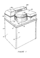
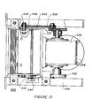
- the recycling appartus generally indicated at 2 comprises an enclosure 4 having a top surface 6 and a front access panel 8 which may conveniently be hinged to permit easy access to crushed containers stored in the apparatus.
- top surface 6 of enclosure 4 is provided with a hinged protective housing or shroud 14 which may be integrally molded to surface 6 as in the drawing or may compirse a removable member.
- Protective housing 14 includes a circular cutaway portion into which a carousel unit 20 fits and which provides a housing around approximately 270° of the carousel unit.
- a hinged top shroud or cover member 16 on housing 14 permits access to carousel 20.
- a front guard member 12 attached to housing 14 is mounted in front of carousel 20 to shield all but a portion of carousel 20 which defines a container receiving station 34.
- Display panels 14a and 14b on the front surfaces of housing 14 contain indicia lights which indicate instructions to the user, as will be described below.
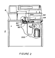
- front access panel or door 8 is shown in an open position which permits accessibility to crushed container bin 280 as well as a hinged security panel or door 54 which houses some of the electrical controls as well as providing security against unauthorized tampering with other electrical controls provided on a control panel 404 behind door 54, as more clearly shown in Figure lb.
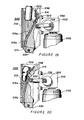
- an AC control panel or module 302 containing a main power breaker switch 304, a main power indicator light 308, a door interlock switch 360a, an interlock indicator light 312 and a crusher motor reversing switch 361.
- a safety interlock switch 314 which shuts off power to machine 2 when door 54 is opened. When the operator wishes to test the apparatus, safety interlock switch 314 may be overridden by door interlock switch 360a.
- Security door 54 is provided with cutout portions 56 and 58 which provide access, respectively, to top shroud release cover handle 66 and keypad 416 both of which are mounted to control panel 404.
- Security door 54 is provided with cutout portions 56 and 58 which provide access, respectively, to top shroud release cover handle 66 and keypad 416, both of which are mounted to control panel 404.
- Security door 54 is secured in a closed and locked position by security door lock 68.
- lock 68 When lock 68 is unlocked, door 54 may be swung open to reveal control panel 404, as shown in Figure lb.
- Keypad 416 which is mounted on control panel 404, communicates with a central control unit 300 which controls the operation of the machine, as will be described.
- Central control unit 300 is also mounted to control panel 404. Central control unit 300 is accessible only when security dock lock 68 is unlocked and security door 54 is open.
- printer cover 18 When cover 16 is raised, as shown in Figure la, printer cover 18 may be raised to permit access to receipt mechanism or printer 290. Cover 18 may be held in a raised position by support arm 18a to facilitate changing of receipt paper or other servicing of printer 18.
- a cartridge receptacle 318 may also be provided on control panel 404 whereby cartridges containing promotional messages may be inserted for display on display panels 14a or 14b, if desired.
- a steel channel 62 located about bracket 90, has bolted thereto a spindle or bearing member 64.
- Spindle 64 receives shaft 80 (Fig. 9a), as will be described below.
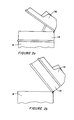
- Figure 3 illustrates a protective skirt 74 which is mounted on a flange 76 on top surface 6.
- 16 Skirt 74 is mounted concentric with spindle 64 and cooperates with surfaces 26a and 26b (Fig. 4) on carousel 20 to form stations 34.
- Carousel member 20 is mounted on top surface 6 of enclosure 4. As more clearly illustrated in Figure 4, carousel member 20 comprises a circular disc or platter 22 having a series of molded members 24 depending therefrom in a circular arrangement. Each member 24 has two opposite concave surfaces 26a and 26b and an outer convex surface 28 having an arc which defines a portion of a circle when a group of members 24 are arranged in circular dependency from disc 22.
- Members 24 are circularly spaced apart on disc 22 in a manner to permit concave surfaces 26a and 26b on adjoining members 24 to define a container receiving station 34 therebetween.
- a handwheel 30 (Fig. 5), which is mounted on top of disc 22 in a manner which will be described below, serves as a handle to permit manual rotation of carousel 20 upon insertion of a container into exposed container receiving station 34 (Fig. 5).
- receiving station is shown in a manner which will accept containers such as beverage containers in an upright manner, it will be understood that station 34 may be arranged in a horizontal manner, and containers may be placed on their sides in the station. That is, the carousel may be arranged so as to rotate about a horizontal axis instead of a vertical axis.
- enclosure 4 contains a bracket 90 which is centrally mounted below top surface 6.
- Bracket 90 in turn, carries a latching mechanism 100 which is operationally attached to carousel 20 to control motion thereof.
- a bearing 102 is attached to bracket 90 and has rotationally mounted thereto a latch disc 104.
- Latch disc 104 contains a central slot 106 (Fig. 10) which is shaped to receive a tongue end 80a of a shaft 80 (Fig. 9a) which has flats thereon to provide a mortise and tenon or socket fit between shaft 80 and latch disc 104.
- a top flange 82 is mounted to the opposite end of shaft 80.
- latching mechanism 100 includes a latch disc 104 which is provided with a series of notches or cammed surfaces 108 terminating respectively in shoulders 110, one of which is latchingly engaged by one end 114 of a detent lever 116 which is pivotally mounted at 118 to bracket 90.
- Lever end 114 is held in locking engagement with shoulder 110 on latch disc 104 by a locking lever or sear 128 which is pivotally mounted on bracket 90 at 130.
- End 132 of sear 128 engages a notch 122 in detent lever 116 to prevent pivoting of detent lever 116.
- Spring bias means 134 urges end 132 of sear 128 into engagement with notch 122 on detent lever 116.
- Sear 128 is moved out of notch 122 into a release position by the action of a solenoid 150 which is activated by the detectors in station 34.
- a solenoid lever 136 which is pivotally mounted to bracket 90 at 138, is attached to solenoid 150 at 140. Solenoid lever 136 is, in turn, pivotally coupled at 142 to a link latch 144. Link latch 144 engages sear 128 via a hooked end 146 to disengage sear end 132 from notch 122 upon activation of solenoid 150.
- latch disc 104 and carousel 20 may be rotated which will permit detent lever 116 to pivot out of engagement with shoulder 110 on latch disc 104.
- optical switches 105 and 105A change state from dark to light sending signals to central control unit 300 which then deenergizes solenoid 150.
- Spring bias means 120 then returns lever 136 and link latch 144 to the shut position. This, in turn, permits spring bias means 134 to return sear 128 into notch 122 on lever 116 to relock latch disc 104.
- 139 identifies a stop which controls the travel of lever 136.
- carousel 20 will only be allowed to rotate 60° to permit the next station 34 to become visible.
- the latching and unlatching sequence as controlled by central control unit 300 is designed to permit the apparatus to function at a speed capable of accepting a container about every 8/10 of a second.
- FIG. 9 The cross-sectional view in Figure 9, as well as the exploded views in Figures 9a through 9c, illustrates parts of the carousel as well as the parts utilized for connecting the carousel to the latching mechanism.
- handwheel 30 which attaches to circular disc 29 with mechanical fasteners 27 through holes 21 and 21A, six of each being provided, respectively.
- a central fastening knob 88 which, in cooperation with circular member 29, provides for a quick disconnect system for the carousel from the latching mechanism.
- a bearing member 64 (Fig. 9a) which is fastened or mounted on channel member 62 as shown in Figure 2.
- shaft or spindle 80 extends through or is inserted into opening 65 of bearing member 64 and extends to latch disc 104 and is operational therewith, as explained earlier.
- a shock absorbing system is inserted between shaft 80 and carousel disc or platter 22 to provide for smoother operation of the carousel when a container, for example, is being manually forwarded from the initial station 34 to the second station and so on.
- the shock absorbing system can provide the added benefit of extending life of the different parts of the machine by minimizing shocks or jolts when the carousel is stopped at the next station.
- the shock absorbing system (shown in Fig. 9b) in accordance with the present invention comprises a top plate member 31 and bottom plate member 33.
- bottom plate member 33 is fastened to flange 82 of spindle 80 using fasteners 81 inserted through holes 33a, 33b and 33c accessed through 33d in top plate 31.
- Top plate member 31 is spaced from bottom plate 33 by rubber shock mounts 84 which are secured to either plate by a friction fit or by fasteners which may comprise threaded inserts 85 and nuts 85A, as shown in Figure 9b.
- the shock mounts are inserted, respectively, in holes 83A and 83B in the plates with which they are aligned, as shown in Fig. 9b.
- bracket 98 having a slot 96.
- This bracket is fastened to the underside of plate 31 so that slot 96 is aligned with opening 35 to receive shaft 92 and pin 94 of knob 88 (see Fig. 9c).
- a circular member 29 is provided as noted earlier and secured to carousel plate 22 by a number of fasteners such as 29a, 29b, etc.
- Circular member 29 is shown in greater detail in Fig. 9c.
- holes 29a, 29b and 29c are shown in Fig. 9c.
- bullet-nosed locating pins 86a, 86b and 86c are shown in the exploded view of Fig. 9b.
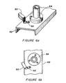
- a light beam 40 from a light source 38 shining onto a photocell 42 is broken which sends a signal to a central control unit 300 (Fig. 24) which, in turn, initiates analysis of the inserted container by activating a sidewall eddy current detector 50, as shown in Figure 6, which may comprise a commercially available unit.
- Light beam 40 is particularly useful when it is desired to know when a container, such as a non-metallic container, is placed in the station. That is, light beam 40 will be broken even when a non-metallic container, e.g. plastic or paper is placed in the station.
- sidewall detector 50 remains on at all times, obviating any need for light source 38 and photocell 42.
- the insertion of an aluminum container is immediately sensed by detector 50; and a signal is sent to central control unit 300 to activate the remainder of the apparatus, as will be discussed below.
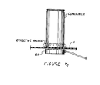
- Detector 50 is mounted inside skirt 74 (Fig. 3) via a bracket 52 to channel 62 (Figs. 6a and 6b) to locate detector 50 midway up the side of receiving station 34. Detector 50 determines the presence or absence of a metallic sidewall. If no metal sidewall is detected, such as might be possible with the insertion of a container used for frozen liquids, an appropriate signal is again caused to be displayed on display panel 14a or 14b indicating the nonacceptability of the container.
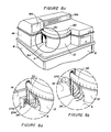
- Detector 50 preferably is adjusted to not only discriminate between metallic and non-metallic sidewalls, but to distinguish steel from aluir'-num as well. Alternatively, this may be accomplished with an optional detector 70 (Fig. 8a) which may be mounted adjacent. detector 50.
- Optional detector 70 may comprise a magnetic detector solely to discriminate between aluminum and steel containers, if desired. This device, however, may be optionally either eliminated (if this function is carried out by detector 50) or selectively disabled for those instances where compacted steel and aluminum containers are to be subsequently put through segregation means at a central processing station.
- central control unit 300 will not activate latching mechanism 100 to permit rotation of carousel 20 nor activate other portions of the apparatus, such as crushing means 200, unless the presence of an aluminum container is detected. It will, of course, be recognized that this aspect of the invention may be modified if it is subsequently deemed desirable to also accept containers constructed of other materials such as steel, e.g. where deposits are required by law for all containers.
- Detector 50 has a range of detection sufficient to permit it to continue to signal the presence of an aluminum container in container receiving station 34 after latching mechanism 100 is unlatched and rotation of carousel 20 has commenced.
- This range of detection which may be termed an "extended presence detection" continues as carousel 20 is rotated until the carousel reaches a point where removal of the container from receiving station 34 would be impossible.
- the purpose of the extended presence detection is to prevent the removal of a container from receiving station 34 by one attempting to defeat the detection mechanism by removal of the container once the recycling process has been initiated.
- the apparatus is further designed to defeat attempts at tampering by an "early presence detector" wherein central control unit 300 is programmed to reject a signal indicating the presence of a metallic container in a station 34 just rotating into view but prior to the possibility of a container being inserted. This, for example, could occur if one were skilled in counterfeiting or tampering. But, for such an early presence detection, detector 50 would continue to send signals to central control unit 300 indicating that aluminum containers were being inserted into the apparatus, even though no containers were actually being inserted.
- an eddy current detector 60 which is mounted below top surface 6 of housing 4 and the exposed receiving station 34 portion of carousel 20, scans the underside of the container for inconsistencies indicative of a pour hole or pull tab signifying that the container has been inserted upside down.
- Eddy current detector 60 may comprise a commercially available unit which electronically scans the lower surface of the container sequentially using a series of detectors, the readings of which are then compared for consistency. Alternatively, a single detector may be mechanically rotated and variations in the readings noted.
- Each of the above described detection means operates electrically and without any mechanical move- ment or sound observable to the user to provide a passive initial screening of the container inserted into receiving station 34. If the container satisfactorily passes all of the tests, an appropriate signal is transmitted to a latching mechanism 100 (Figs. 10 and 11) which normally prevents rotation of the carousel. Upon receipt of this signal, the latching mechanism is disabled by activation of a release solenoid permitting rotation of carousel 20 with the container inserted in station 34, as will be explained below.
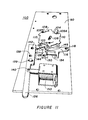
- the container passes to a second analysis station where, as shown in Figures 12, 12a and 12b, the weight of the container may be determined.
- a platform 160 which is independent of the work surface, i.e. top surface 6. Coupled to platform 160 is a load cell 170 which measures the weight of the container. Load cell 170 is mounted via bracket 172 to latch plate mounting bracket 90. If the weight exceeds a predetermined amount, indicative of the fact that the container is not empty, the container will not be crushed, but instead may either be passed to a reject station or allowed to fall into a separate receptacle. If desired, central control unit 300 may also have stored therein information with regard to a minimum acceptable weight. This determination may be found to be useful to defeat attempts to circumvent the proper functioning of the appartus as by insertion of bits or pieces of aluminum rather than a whole container.
- the height of the container may also be determined in the second station by shining a beam of light from a light source 180 onto a parabolic reflector 184 which reflects the light beam back toward the container and onto a calibrated sensing screen 188 which may comprise a series of vertically mounted photoelectric cells. The portion of the light beam blocked by the container and, therefore, not falling on screen 188, will indicate the height of the container.
- the measured height and weight data may be fed into central control unit 300 which may have stored, in appropriate memory cells, information concerning acceptable weight to height ratios indicative of known commercially available containers which may be recycled. If the weight to height ratio does not match, indicative of either a container not empty or a container not otherwise suitable for recycling, the container may then be rejected.
- central control unit 300 stores and accumulates the acceptance in preparation for the issuance of a receipt for the total number of containers accepted.
- Rejection mechanism 190 comprises an ejection arm 192 of a solenoid (not shown) energized by a signal from central control unit 300. Ejection arm 192 pushes the rejected container against a wall or finger portion 194 which is positioned over a rotatable turntable 196 which is simultaneously energized by central control unit 300. Turntable 196 rotates the container to an exit station 198.
- a refuse mechanism may be provided for initial receiving station 34 incorporating some of the features of reject mechanism 190.
- a refuse mechanism 204 comprises a solenoid arm 206 which is powered by a solenoid (not shown). If any of the initial tests (bottom wall detector, sidewall detector, etc.) are unacceptable, central control unit 300 energizes the refuse solenoid to push the container out of station 34.
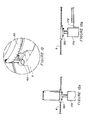
- Crushing means 200 is located below an opening 202 in top surface 6 through which the container passes upon further rotation of carousel 20.
- central control unit 300 activates crusher means 200.
- Crusher means 200 comprises a modified V-shaped opening 210 formed by stationary wall 212 and an extension 214 of movable member or jaw 216 together with a pair of sidewalls 240 and 242.
- Sidewalls 240 and 242 are each provided with a pair of mounting ears 230 which are used to shock mount crusher means 200 to a bracket 234 via rubber bushings 232.
- Extension 214 is hinged to jaw 216 at 222 and is provided with a guide pin 244, the ends of which ride, respectively, in slots 246a and 246b in sidewalls 240 and 242. Extension 214 acts as a container guide to direct falling containers into engagement with crusher jaw 216.
- Movable member 216 is pivotally attached, at its lower end, to sidewalls 240 and 242 by a pin 220. Spaced from the lower end of member 216, a pair of pins 224 and 226 are mounted respectively each on one side of member 216 and pass through slots 236 and 238, respectively, in sidewalls 240 and 242. Pin 224 is attached to a lever 228 and pin 226 is attached to a lever 229. Levers 228 and 229 are mounted eccentrically to wheels 252 and 254 on opposite sides of a gearbox 256. Gearbox 256 reduces the speed of a motor 258 which is used to power crushing means 200. As the container to be crushed falls through opening 202, motor 258 moves jaw 216 from an open position toward the fixed or stationary wall 212.
- motor 258 was activated by central control unit 300 upon reception of a signal from detector 50.
- the falling of a container into opening 210 may not always coincide with the opening of jaw 216.
- the movement of jaw 216 is reciprocal from an open to shut to open position, this is not important.
- Crusher means 200 and more particularly crusher motor 258, will continue to run for 45 seconds in the preferred embodiment after the last signal sent to central control unit 300 by detector 50 indicating the presence of an acceptable container in receiving station 34. This is deemed to be a sufficient time period to permit further rotation of the carousel after insertion of the last container. After expiration of this time period, central control unit 300 shuts off motor 258.
- the apparatus does not require that an accepted container be crushed prior to issuance of a receipt. After the last container is inserted and accepted (by successfully passing the weight test in the second station) a receipt issued will include that container even if the 45 second period elapses and the crusher shuts down before crushing the last container. The last container will simply remain in the apparatus and be crushed when the next user reactivates the apparatus by insertion of another container.
- Disabling means such as a photocell, may also be provided to be activated if the container does not fall through opening 210 within a predetermined number of crushing cycles to indicate to the user that the crushing mechanism is jammed or, alternatively, -that the holding receptacle beneath crushing means 200 is full (Fig. 23) and can accept no further crushed containers. That is, a light beam from source 282 may be directed across bin 280 to a reflector 284 and then to a photocell 285 which can be programmed to stop the machine when the beam is broken which is indicative of a full bin. With respect to jamming of the crusher jaws, a switch may be employed to determine the continuation of the crushing cycle.
- the disabling means may be used to activate a visual and/or audible signal indicating that service personnel should be summoned to remedy the problem.
- the disabling means should also be capable of overriding the delatching mechanism so that no further containers may be inserted into apparatus 2 until the problem has been remedied.
- means are also provided in apparatus 2 (Fig. 8) for reading a code which may have been placed on the container, such as the Universal Product Code (UPC), which is placed on food and beverage containers.
- UPC Universal Product Code
- This coded information may, in certain instances, contain data with regard to amounts and sources of prepaid deposits as may be required by the laws of the several states.
- This information is read and stored in appropriate storage means to provide proper credits or debits based on deposits prepaid or owed.
- the UPC reader may keep records of individual manufacturers who have collected deposits on containers and then print out a total on a monthly basis showing how much that manufacturer should be billed. The printout may be a monthly accumulation of the containers collected from various manufacturers with separate totals for each.
- UPC reader 270 may be placed adjacent station 34 at 274 to read the code as the container is initially inserted into the exposed station 34. Instructions may be provided on display panels 14a or 14b to indicate the proper orientation of the coding indicia during insertion of the container into station 34 to insure proper functioning of code reader 270.
- the machine may be set up to add the proper reading of the UPC to the other initial screening functions which must be successfully completed prior to activation of latching mechanism 100 to permit rotation of carousel 20 to allow insertion of further containers.
- the device may be arranged to simply ignore the absence of an acceptable code if this is not deemed necessary to the functioning of the apparatus.
- an additional code can be affixed to the top or bottom of the can.
- This additional code may be complementary to the UPC.
- a complementary code scanner 275 may be located in the bottom of station 34, as shown in Figure 8. Or, a scanner may be placed over the entrance to station 34 to read the complementary code on the lid, as indicated in Figure 8b. The information read from the complementary code is read and stored in the appropriate storage means to provide proper credits and debits based on deposits, as noted hereinabove.
- a container is inserted into the exposed station 34 of carousel 20 breaking the path of beam 40 from light source 38 shining onto photocell 42.
- a signal is then sent from photocell 42 to central control unit 300 which, in turn, activates sidewall detector 50, bottom wall detector 60 and, optionally, steel-aluminum detector 70 and Universal Product Code (UPC) reader 270.
- the container is then analyzed and the signals from these sources are fed back to central control unit 300. If the signals received indicate the presence of an acceptable container, a signal is sent by central control unit 300 to latching mechanism 100 permitting rotation of carousel 20 via handwheel 30.
- the container is thus carried to the second position or station where it may be further analyzed for correct weight and height by signals sent to load cell 170 and light source 180. Signals from load cell 170 and sensing screen 188 are then sent back to central control unit 300. If the height and weight relationship is acceptable, central control unit 300 records the acceptance and accumulates the tally prior to issuance of a receipt. In another embodiment, gross weight alone may be utilized to determine acceptable containers.
- the carousel may be again rotated by the user and the timer for crusher motor 258 is reinitiated by central control unit 300.
- the container passing from the second station then is crushed by crusher jaw 216.
- central control unit 300 sends an appropriate signal to receipt mechanism 290 which then may print a receipt which is redeemable by a cashier in the store in which the apparatus is located. Alternatively, a coin or coins may be dispensed.
- central control unit 300 If the container is not inserted in an upright position at the first position of station 34, a signal is sent to central control unit 300 which, in turn, causes a message to be displayed to the user on panel 14a or 14b indicating the problem. Similarly, if the container does not have a proper metallic sidewall or, if the UPC reader is used, it is indicated that the container is unacceptable, central control unit 300 sends signals to the display panels indicating to the user the nature of the problem. In any event, the latching mechanism 100 will not be acticated to release carousel 20 until a container acceptable to the apparatus is inserted into station 34. Thus, the apparatus performs a plurality of initial screening tests upon insertion of a container into exposed station 34 and either unlatches the carousel or displays the appropriate message indicating the reason for unacceptability without any movement perceptible to the user.
- the finding of an unacceptable height or weight or a relationship determined by a ratio of height to weight in the second screening position or station may result in shutdown of the machine, ejection of the container or rerouting of the container into a separate storage area.
- central control unit 300 is mounted on control panel 404 on the front of recycling unit 2.
- Central control unit 300 may be an electro-mechanical timing unit.
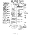
- central control unit 300 is in the form of a microcomputer having a functional block diagram, as shown in Figure 25.
- central control unit 300 comprises a microprocessor 310; an oscillator 316; a read-only memory (ROM) 320; a primary, volatile, random access read/write memory (RAM) 326; a secondary non-volatile, radom access read/write memory (RAM) 330; a clocked interrupt 336; a stall alarm timer 340 a power failure monitor 346; a power supply 350; inputs 352-375; and outputs 376-399.
- ROM read-only memory
- RAM random access read/write memory
- RAM secondary non-volatile, radom access read/write memory
- Microprocessor 310 preferably comprises an 8 bit microprocessor having integral clock ciruits, such as, for example, an MC6808 microprocessor available from Motorola.
- Oscillator 316 has a 4 MHz crystal to produce a 1 MHz instruction cycle rate to control the clock circuits in microprocessor 310.
- the double-arrow lines denote data buses and address buses.
- the operating program and data concerning, for example, the weight range of an acceptable container, are stored in the read-only memory 320 which contains 32K of memory space.
- the data derived during operation is stored in the primary random access memory 326 which has 2 K of random access memory.
- the secondary, or back-up, random access memory 330 has an independent power supply which may consist, for example, of a lithium battery having a five year life.
- Secondary RAM 330 contains 256 bytes of CMOS (low power consumption) memory. Secondary RAM 330 is used for storing of data during power interrupts, as will be explained below.
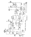
- Clocked interrupt 336 comprises a hardware divider chain, as shown in Figure 26, which provides central control unit 300 with a timed interrupt which can be used to make accurate measurements of process activity.
- the commercially available, integrated or serialized circuits e.g. 74LS390
- Clocked interrupt 336 and stall alarm timer 340 provide a circuit which measures the response time of central control unit 300 and deenergizes all AC loads, such as the crusher motor, if central control unit 300 fails to respond to the timer circuit in a specified period of time.
- Power failure logic or circuit 346 monitors the AC line voltage and provides a signal to microprocessor 310 if there is an interruption in power so that microprocessor 310 can take certain actions such as to store data in battery powered RAM 330.
- Inputs 352-375 comprise 21 optically isolated digital inputs and 4 direct digital inputs.
- Outputs 376-399 comprise 15 optically isolated digital outputs and 4 direct digital outputs.
- the optically isolated inputs and outputs are used to provide noise immunity to central control unit 300 by electrically isolating unit 300 from the input and output devices which respectively monitor and control the individual operational components of the apparatus.
- each of the optically isolated inputs is further provided with a light emitting diode (LED) status indicator on control panel 404 within apparatus 2 and accessible via front access panel 8 and security door 54, as shown in Figure lb.
- LED light emitting diode
- Power supply 350 which supplies the DC voltages to central control unit 300, is provided with an isolation transformer 322 and an AC line noise suppressor 324, as shown in Figure 28, to provide further noise immunity to central control unit 300.
- central control unit 300 may also be provided with an analog to digital converter 334 for input signals not in digitized form, as will be discussed below with respect to the eddy current detector and the load cell for weight determination.
- inputs 352, 353, 354 and 355 comprise four digitized inputs from a series of vertically mounted photoelectric cells comprising sensing screen 188 of the container height detector, as previously described with respect to Figure 13.
- the detected height of the container is compared to a particular weight range for containers of that height.
- the weight is compared to the weight range for this height. If the container weight is not within the range, the can is rejected.
- Microprocessor 310 then sends a signal via output 376 activating a reject means such as shown in Figure 13.
- Inputs 360 and 362 are connected to safety interlock safety switches 360a and 360b as shown in Figure la, which deactivate the motors, e.g., crusher motor 258 when, respectively, front door 8 or top cover 16 are opened.
- motors e.g., crusher motor 258
- Input 391 is connected to UPC reader 270 or 275 to feed a signal into microprocessor 310 indicative of any code on the inserted container.
- Input 364 is connected to bin full detector 281 which comprises photocell 285 and light source 282, as shown in Figure 23.
- bin full detector 281 which comprises photocell 285 and light source 282, as shown in Figure 23.
- Input 365 receives a signal from (optional) ferrous metal detector 70 which indicates the presence of ferrous metal (i.e., a steel container).
- ferrous metal i.e., a steel container.
- the Steel Can LED light is activated as well as refuse motor or solenoid 205.
- Input 366 is connected to detector 50 which signals central control unit 300 when a container having an aluminum sidewall is inserted into container receiving station 34.
- a light beam 40 from a light source 38 may be provided which, when interrupted, causes a difference in the signal and photocell 42 indicating the presence of a container (or foreign object). Such a signal may then be transmitted to central control unit 300 via a presence detector input 367.
- restart switch 410 which is located on the top of cover 16, as shown in Figure lb. This, in turn, activates input 368.
- a Request for Receipt switch 412 located on the front of cover 16 on the top of the machine, as seen in Figures la and lb, also comprises a momentary push button switch which activates input 369 to signal to central control unit 300 that the customer wishes to have a receipt printed.
- Input 370 is connected to crusher motor 258 to provide a signal to central control unit 300 indicating that the crusher is running.
- Optical limit switches 105 and 105A monitor the rotation of latch disc 104 and a signal the progress of rotation to central control unit 300 via inputs 371 and 372.
- a key pad 416 as seen in Figure la, comprises a sixteen character keyboard which may be used as an auxiliary input for maintenance purposes. Key pad 416 is interconnected with central control unit 300 via input 373.
- Weight detector 170 is connected via input 374 to central control unit 300 to transmit data concerning the weight of the container inserted into the apparatus.
- the output from weight detector 170 may be in digitized form or, alternatively, input 374 may be via analog-digital converter 334 to central control unit 300, as shown in Figure 25.
- input 375 from upside down detector or bottom surface eddy current detector 60 may either be in digitized form or interconnected with central control unit 300 through analog-digital converter 334.
- central control unit 300 may be programmed to activate the reject turntable motor 406 via output 376.
- the weight detector cam drive motor 174 may be set to be activated by output 378, and can crusher motor 258 is activated by a signal from output 380.
- the refuse motor or solenoid mechanism 204 may be programmed to be activated by output 384, and rejection mechanism solenoid 190 may be set to be activated by output 386.
- a signal is sent to central processing unit 300 via input 369, which, in turn, causes a signal to be sent, via output 382, to receipt mechanism or printer 290 to print and issue a receipt to the customer.
- Solenoid 150 of latching mechanism 100 is activated by a signal from output 390 after the inserted container has passed the tests in initial container receiving station 34.
- Display panel 14a comprises a 16 character alphanumeric display which is controlled by central control unit 300 via output 392.
- Central control unit 300 may. also provide additional visual control signals such as a Continue Turning Handle indicator via output 394, a Call Manager indicator via output 395, a Container Not Empty indicator via output 396, a Not Beverage Can indicator indicating that the container is not a metal container via output 397, a Steel Can indicator indicating the container is a steel container via output 398 and an indicator indicating that the container is upside down via output 399.
- a container is inserted into container receiving station 34 of carousel 20, breaking the path of beam 40 from light source 38 shining onto photocell 42.
- a signal is then transmitted through an input 369 to central control unit 300 indicating that a container has been inserted.
- Sidewall detector 50 and steel detector 70 then send signals respectively via inputs 366 and 365 to central control unit 300 indicating whether the container has a metal sidewall and whether the sidewall is steel. If the container does not have a metal sidewall, Not Beverage Can LED is activated via output 397. If the container has a steel sidewall, the Steel Can LED is activated via output 398.
- the Universal Product Code reader 270 sends a signal to central control unit 300 via input 375 indicating what sort of deposit, if any, has been collected and by whom.
- central control unit 300 After receiving the initial input signals from the respective detectors in initial receiving station 34, central control unit 300 activates can crusher motor 58 via output 380. A signal is also sent via output 390 to solenoid 150 to unlatch the carousel permitting rotation.
- Central control unit 300 also, at this point, initiates several maintenance checks to insure that the equipment is functioning properly, as noted in the flow charts.
- Central control unit 300 checks if 8/10 second time period has elapsed since last insertion of a container. The purpose of 8/10 second time period is to prevent a rotation of the carrier until the previous can has been processed. If the 8/10 second time period has not expired, the apparatus waits for it to expire.
- Central control unit 300 then initializes a 45 second software timer. This timer circuit functions to monitor activity by the user, i.e., rotation of carousel 20, after insertion of an acceptable container in station 34.
- Central control unit 300 checks, via input 370, whether the crusher motor is running or not, indicating the possibility of a jammed condition.
- the machine is inactivated (i.e., the crusher motor is shut off). If the carousel is rotated, central control unit 300 checks for the precence of an aluminum can as the carousel is rotated.
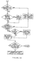
- central control unit 300 the turning of the carousel is monitored by central control unit 300 via optical limit switches 105 and 105A which send signals to central control unit 300 via inputs 371 and 372. If the carousel has passed the point of no can removal, solenoid 150 is deenergized and the operation is permitted to proceed. It will be further noted from the flow charts of Figures 30-33 that other checks for errors are also made by the programming of central control unit 300 to insure proper functioning of the apparatus.
- the container is proceeding toward the crusher.
- the first rotation by the user moves the container to the weight and height checking position. If no subsequent containers are inserted by the user a receipt is issued to the user, either in response to a pressing of the Request for Receipt button by the user or the elapse of 45 seconds, as previosly discussed.
- solenoid 150 is again activated, permitting further rotation of the carousel by the user. This results in the first container reaching the crushing station where the container drops into the jaws of the crusher as previously discussed.
- the spirit and purpose of the invention is to provide an apparatus for the receipt of recyclable containers by the analysis and initial acceptance or rejection of a container for recycling without mechanical movement apparent to the user.
- the analysis and initial acceptance is initiated by the insertion of a container into a container receiving station on a rotatable carrier wherein detecting means coupled to the receiving station to determine the presence of a container comprised of material acceptable for recycling include scanning means for reading code markings on the container. Means are also provided to subsequently permit manual actuation of the rotatable carrier if the container is acceptable for recycling.
- the spirit and purpose of the invention is to provide a recycling apparatus capable of determining the presence of a container in a pocket in a rotatable carrier, the type of material in the sidewall of the container, and optionally, may include detection of the orientation of the container and reading a product code on the container wall; all prior to any movement or sound perceptable to the user; and then, if the container is acceptable according to the prior tests, further processing the container leading to the eventual crushing of the accepted container.
- a recycling apparatus comprising an enclosure having a manually rotatable carrier with a first station comprising a pocket in the carrier to receive a container with means associated therewith; to detect the presence of a container in the pocket; to determine the acceptability of the container, including the type of material in the wall of the container; to permit manual rotation of the carrier if the container is found to be acceptable in the first station; to determine the weight of the container to eventually crush a container found to be acceptable for recycling; and to issue a receipt for the container.
- the spirit and purpose of the invention is to provide recycling apparatus capable of detecting the presence of a recyclable container in a pocket or station of a rotatable carrier which is mounted to the apparatus by shock absorbing means which inhibit damage to the apparatus by rapid or jerking motions during rotation of the carrier to transport an inserted container to one or more subsequent stations for testing and eventual crushing of a container accepted for recycling.
- the process provides for the determination of acceptability of a container for recycling by checking the type of metal in the container as well as the weight, height and orientation of the container.
- the process provides for the tallying of accepted and crushed containers and issues a receipt to the user.
- the process also monitors the proper functioning of the apparatus and displays appropriate messages to the user and/or maintenance personnel. While the process has been described with respect to a preferred embodiment, minor modifications may be made which will not depart from the spirit of the invention which is to be limited only by the scope of the appended claims.
Landscapes
- Engineering & Computer Science (AREA)
- Mechanical Engineering (AREA)
- Physics & Mathematics (AREA)
- General Physics & Mathematics (AREA)
- Processing Of Solid Wastes (AREA)
Applications Claiming Priority (14)
| Application Number | Priority Date | Filing Date | Title |
|---|---|---|---|
| US06/559,424 US4510860A (en) | 1983-12-08 | 1983-12-08 | Latching mechanism for manually rotatable carrier in apparatus for processing recyclable containers |
| US559374 | 1983-12-08 | ||
| US06/559,425 US4512253A (en) | 1983-12-08 | 1983-12-08 | Apparatus for processing recyclable containers |
| US06/559,423 US4558775A (en) | 1983-12-08 | 1983-12-08 | Apparatus for passive analysis of containers to determine acceptability for recycling |
| US06/559,374 US4510857A (en) | 1983-12-08 | 1983-12-08 | Container recycling apparatus having shock mounted manually rotatable carrier |
| US559321 | 1983-12-08 | ||
| US06/559,373 US4519307A (en) | 1983-12-08 | 1983-12-08 | Container recycling apparatus using scanning means to read code markings on containers |
| US06/559,233 US4519306A (en) | 1983-12-08 | 1983-12-08 | Process for recycling containers |
| US559373 | 1983-12-08 | ||
| US559423 | 1983-12-08 | ||
| US06/559,321 US4526096A (en) | 1983-12-08 | 1983-12-08 | Apparatus for processing used containers having improved crusher means |
| US559424 | 1995-11-15 | ||
| US559233 | 2000-04-26 | ||
| US559425 | 2000-04-27 |
Publications (1)
| Publication Number | Publication Date |
|---|---|
| EP0146322A2 true EP0146322A2 (de) | 1985-06-26 |
Family
ID=27569840
Family Applications (1)
| Application Number | Title | Priority Date | Filing Date |
|---|---|---|---|
| EP84308549A Withdrawn EP0146322A2 (de) | 1983-12-08 | 1984-12-07 | Rückführungsvorrichtung für Behälter |
Country Status (1)
| Country | Link |
|---|---|
| EP (1) | EP0146322A2 (de) |
Cited By (3)
| Publication number | Priority date | Publication date | Assignee | Title |
|---|---|---|---|---|
| EP0718811A1 (de) * | 1994-12-23 | 1996-06-26 | C.M.S. S.p.A. | Vorrichtung zum Identifizieren von Objekten |
| WO2000018571A1 (en) * | 1998-09-30 | 2000-04-06 | HALLDÉN, Kerstin | Refund container apparatus |
| EP2085935A2 (de) | 2008-01-29 | 2009-08-05 | Wincor Nixdorf International GmbH | Erkennung von Material und Füllzustand von Leergutbehältern |
-
1984
- 1984-12-07 EP EP84308549A patent/EP0146322A2/de not_active Withdrawn
Cited By (4)
| Publication number | Priority date | Publication date | Assignee | Title |
|---|---|---|---|---|
| EP0718811A1 (de) * | 1994-12-23 | 1996-06-26 | C.M.S. S.p.A. | Vorrichtung zum Identifizieren von Objekten |
| WO2000018571A1 (en) * | 1998-09-30 | 2000-04-06 | HALLDÉN, Kerstin | Refund container apparatus |
| EP2085935A2 (de) | 2008-01-29 | 2009-08-05 | Wincor Nixdorf International GmbH | Erkennung von Material und Füllzustand von Leergutbehältern |
| EP2085935A3 (de) * | 2008-01-29 | 2010-01-06 | Wincor Nixdorf International GmbH | Erkennung von Material und Füllzustand von Leergutbehältern |
Similar Documents
| Publication | Publication Date | Title |
|---|---|---|
| US4512253A (en) | Apparatus for processing recyclable containers | |
| US4573641A (en) | Glass bottle collection and crushing apparatus | |
| US4558775A (en) | Apparatus for passive analysis of containers to determine acceptability for recycling | |
| US4519307A (en) | Container recycling apparatus using scanning means to read code markings on containers | |
| US4285426A (en) | Container redemption apparatus and process | |
| US4492295A (en) | Automated redemption center for metal containers | |
| US4653627A (en) | Reverse vending machine | |
| US4345679A (en) | Container collection apparatus with electromagnetic sensor and method | |
| US4440284A (en) | Automated aluminum can redemption center for direct return deposit payout | |
| US5248102A (en) | Device for handling empty beverage containers | |
| US5257741A (en) | Method and apparatus for container redemption and recycling | |
| US5415264A (en) | Automatic vending machine for newspapers | |
| US4829428A (en) | Beverage container sorting, accounting, and disposal method with compartmentalized hamper and can crusher | |
| US4411351A (en) | Bottle dispensing and control system | |
| US4510860A (en) | Latching mechanism for manually rotatable carrier in apparatus for processing recyclable containers | |
| US4324325A (en) | Apparatus for collection of metallic containers and method therefor | |
| US4454028A (en) | Can sorting method and apparatus | |
| WO1994004446A1 (en) | An apparatus for storing and dispensing articles | |
| WO2018150657A1 (ja) | 物品回収装置 | |
| WO2011066839A1 (en) | Reverse vending system for batch registration of used beverage containers | |
| US4519306A (en) | Process for recycling containers | |
| US4526096A (en) | Apparatus for processing used containers having improved crusher means | |
| US4443697A (en) | System and method for selecting and segregating containers | |
| US4510857A (en) | Container recycling apparatus having shock mounted manually rotatable carrier | |
| EP0146322A2 (de) | Rückführungsvorrichtung für Behälter |
Legal Events
| Date | Code | Title | Description |
|---|---|---|---|
| PUAI | Public reference made under article 153(3) epc to a published international application that has entered the european phase |
Free format text: ORIGINAL CODE: 0009012 |
|
| AK | Designated contracting states |
Designated state(s): CH DE GB IT LI SE |
|
| STAA | Information on the status of an ep patent application or granted ep patent |
Free format text: STATUS: THE APPLICATION HAS BEEN WITHDRAWN |
|
| 18W | Application withdrawn |
Withdrawal date: 19860527 |
|
| RIN1 | Information on inventor provided before grant (corrected) |
Inventor name: LEFTAULT, CHARLES J. Inventor name: LABARGE, ROD L. Inventor name: HORANSKY, FRANK J. Inventor name: ARNDT, ERIC D. Inventor name: SCHERF, THOMAS W. Inventor name: HAWKINS, RONALD G. Inventor name: GREEN, JERROLD D. Inventor name: POHLENZ, ELMER E. |