EP0146267A2 - Magnet system - Google Patents
Magnet system Download PDFInfo
- Publication number
- EP0146267A2 EP0146267A2 EP84307979A EP84307979A EP0146267A2 EP 0146267 A2 EP0146267 A2 EP 0146267A2 EP 84307979 A EP84307979 A EP 84307979A EP 84307979 A EP84307979 A EP 84307979A EP 0146267 A2 EP0146267 A2 EP 0146267A2
- Authority
- EP
- European Patent Office
- Prior art keywords
- magnetic field
- sheet
- magnet
- generating means
- plate
- Prior art date
- Legal status (The legal status is an assumption and is not a legal conclusion. Google has not performed a legal analysis and makes no representation as to the accuracy of the status listed.)
- Granted
Links
Images


Classifications
-
- H—ELECTRICITY
- H05—ELECTRIC TECHNIQUES NOT OTHERWISE PROVIDED FOR
- H05K—PRINTED CIRCUITS; CASINGS OR CONSTRUCTIONAL DETAILS OF ELECTRIC APPARATUS; MANUFACTURE OF ASSEMBLAGES OF ELECTRICAL COMPONENTS
- H05K9/00—Screening of apparatus or components against electric or magnetic fields
Landscapes
- Engineering & Computer Science (AREA)
- Microelectronics & Electronic Packaging (AREA)
- Shielding Devices Or Components To Electric Or Magnetic Fields (AREA)
- Reciprocating, Oscillating Or Vibrating Motors (AREA)
- Magnetic Resonance Imaging Apparatus (AREA)
- Details Of Measuring And Other Instruments (AREA)
Abstract
Description
- The invention relates to a magnet system including magnetic field generating means and a shield for screening the magnetic field generating means to a given degree.
- There is a particular problem where large field strength magnets are employed in that it is desirable to screen the external magnetic field as much as possible. For example, in the field of nuclear magnetic resonance (NMR) imaging a magnet providing a bore field of about 0.5 T is required and such a magnet produces an undesirably strong external field over a wide area. It is thus desirable to screen the magnet and one possible solution would be to provide a perfectly spherical shell of magnetic material around the magnet with the magnet at the centre of the sphere.
- In practice, a spherical shell is not obtainable and at present the walls of a room in which a magnet is positioned are lined with sheets of iron to approximate to a spherical shell. Such a shield provides a degree of screening but the weight of the iron sheets presents considerable problems in constructing the shield which is cumbersome and expensive.
- In accordance with the present invention, a magnet system comprises magnetic field generating means; and a shield including at least one sheet of magnetic material, the size and position of the or each sheet relatively to the magnetic field generating means being such that in use at the edge of the sheet or sheets the component of magnetisation parallel to the sheet in the direction of the magnetic field is less than or substantially equal to zero.
- The inventors have recognised that the arbitrary placing of a magnetic sheet in a magnetic field may cause some parts of the sheet to be adversely magnetised in such a way that they actually increase, rather than decrease, the fringe magnetic field in their vicinity. If, however, the sheet of magnetic material is of such a size and position that the component of magnetisation parallel to the sheet in the direction of the magnetic field is less than or substantially equal to zero at the edge of the sheet then there will be no increase in magnetic field and a high proportion of magnetic flux will be constrained to flow through the plate producing an efficient screening effect. It should be recognised that the shield does not eliminate the external magnetic field on the side of the sheet remote from the magnetic field generating means but reduces it to a predetermined magnitude far more efficiently than the prior methods.
- When the component of magnetisation parallel to the sheet in the direction of the magnetic field is less than zero at a particular point, this means that the magnetisation of the sheet at that point opposes the magnetic field due to the magnetic field generator.
- The result of this invention is that a shield can be developed for use at predetermined distances from the magnetic field generating means (in general closer to the generating means than the walls of the room in which the system is located) and less magnetic material is required thus resulting in a cheaper and more convenient shield. In practice, the distance of the sheet or sheets from the magnetic field generating means will be determined so as to achieve the maximum screening effect possible for a given thickness of sheet.
- Preferably, a plurality of sheets of magnetic material are provided around the magnetic field generating means parallel to the axis of the magnetic field.
- This construction leads to a particularly advantageous arrangement in which sheets at each end of the magnetic field generating means transverse to the axis can be omitted since the sheets parallel to the axis provide an optimum return path for the magnetic flux. This is particularly useful in the case of NMR imaging where access to the bore of the magnetic field generating means (normally a superconducting magnet) is important.
- Although it is most efficient to provide the shield completely around the axis of the magnetic field, in some systems one or more of the sheets may be omitted without degrading significantly the shielding effect. In particular, where the system is housed on the ground floor of a building, the lowermost sheet may be removed since it is not generally required to screen the magnetic field in that direction.
- Preferably, the component of magnetisation parallel to the or each sheet in the direction of the magnetic field, at the edge of the sheet, is substantially equal to zero but in some cases this requirement may lead to plates which are undesirably large. In such cases, the dimensions of the plate may be reduced but in this case, it is preferable if such a reduction is carried out in a symmetrical manner. Thus:
- (a) it should be reduced symmetrically about its plane;
- (b) a perpendicular to the sheet through the mid plane of the sheet should pass through the axis of the magnetic field generated by the magnetic field generating means; and
- (c) if one sheet requires a change in its dimensions then all other sheets should be likewise modified so that all sheets are of the same size.
- Some examples of magnet systems in accordance with the invention will now be described with reference to the accompanying drawings, in which:-
- Figure 1 is a schematic view of an iron sheet illustrating the variation in the component of magnetisation parallel to the sheet;
- Figures 2A-2C illustrate the variation in the component of magnetisation parallel to three iron sheets of different sizes;
- Figure 3 illustrates a complete shield;
- Figures 4A-4C are schematic end, side, and perspective views respectively of NMR imaging apparatus incorporating a shield according to the invention, the magnet being omitted in Figure 4C; and,
- Figures 5A and 5B illustrate the magnitude of the external magnetic field generated by the apparatus shown in Figures 4A-4C.
- The magnetic field at any point in an iron plate placed in a magnetic field can be determined by using the well known scalar potential method. The total magnetic field intensity (HT) at any point in an iron plate is the sum of the field due to the magnetic field generator generating the magnetic field (HG) and the field due to the "magnetic charges" in the remainder of the iron plate (HI) whose presence is due to the affect of the magnetic field generated by the magnetic field generator. Thus:

- The magnetic field intensity (
H I) due to the "magnetic charges" in the iron plate is given in general by the following equation
- The "magnetic charge density" (M) at any given point is given by:

- Where χ is the magnetic susceptability of the magnetic material forming the plate, in this case iron. Thus, the magnetic field intensity at any point P in the iron plate as a function of the fields at all possible points Q is given by:

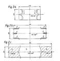
- The solution of equation (4) can be determined for plates of different dimensions and is illustrated graphically in Figure 1. Figure 1 illustrates an
iron plate 1 of rectangular form withcurves plate 1 where the axis of the magnetic field generated by a superconducting coil (not shown) lies in the Z direction. The innerdashed line 4 in Figure 1 illustrates how the critical dimensions of a particular plane can be determined. Theline 4 lies along the locus of points where the magnetisation is substantially perpendicular to the plate 1 (ie. the M component is zero.) Within the area of the plate defined by theline 4, the M component is less than zero. - The differences between plates of different dimensions can be seen more clearly with reference to Figure 2. Figures 2A-2C illustrate three plates of the same thickness (0.5 inches) and width (2 metres) but of varying lengths and the M magnetisation when each plate has been positioned parallel with the axis of and at two metres from a superconducting solenoid (not shown) generating a bore field of 0.5T.
- The plate shown in Figure 2C has a length of 8 metres and an
area 5 where the Mz component of magnetisation is negative and opposes the magnetic field but also large 6 where the M z component of magnetisation is positive which is undesirable. - The plate shown in Figure 2B has a length of 6 metres and is of the optimum size in which the (M) component of magnetisation parallel to the plate at the edges of the plate is substantially zero. It will be seen from this figure that by "substantially" we mean that it is possible for there to be small portions of the plate where Mz is positive but these portions are small relatively to the overall dimensions of the plate. The areas of positive Mz are indicated by reference to numeral 6'.
- The plate shown in Figure 2A has a length of 4 metres and has no areas where M is positive and will therefore only reduce the external field. However, by virtue of its shorter length it will have fewer "negative charges" and will thus be less effective at reducing the external field than the plate shown in Figure 2B. In the Figure 2A plate,
contours - In practice, for any particular magnet, equation (4) is solved with the premise that each plate should be of rectangular form, have a predetermined thickness (for example 0.5 inches) and be positioned at a predetermined distance from the magnet. These constraints are determined from practical considerations. For example, the thickness is chosen to correspond to the number of "negative charges" required to make the desired reduction in external field while the distance from the magnetic field generator will be governed by the size of the room in which the assembly is sited. This enables equation (4) to be solved at least by computer to define the dimensions of plates where the component of magnetisation parallel to the plate in the direction of the magnetic field, at the edges of the plate, will be substantially zero.
- Figure 3 illustrates a shield (for a magnet which has been omitted for clarity) which comprises four
rectangular plates 9 parallel with and equally spaced from anaxis 11 of the magnetic field and twoend plates 10 transverse to the axis of the magnetic field. Where the magnet is a solenoid theaxis 11 will correspond to the axis of the solenoid. - It will be seen in Figure 3 that the
plates 9 which are of the relevant critical dimensions do not completely enclose the space between the plates. - Figures 4A and 4B illustrate schematically a shielded
superconducting magnet 12. Figure 4C is a perspective view of the shield with themagnet 12 omitted. The shield comprises three rectangular iron plates 13-15 arranged on either side and above themagnet 12 and asmall base plate 16 arranged under themagnet 12. All the plates 13-16 have a thickness of 12.7 mm and a width of 2.2 m. The plates 13-15 have a length of six metres. Thebase plate 16 is small in this example since the magnet rests on the floor of a building. In some cases, thebase plate 16 could be omitted completely in this situation. - It will be seen from Figure 4C and from Figures 5A, 5B (to be described below) that the plates 13-16 are positioned relatively closely together and hence close to the
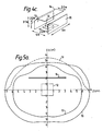
magnet 12. In this example, end plates have been emitted to allow easy access to the bore of themagnet 12. - Figures 5A and 5B illustrate the form of the nagnetic field around the
magnet 12 generating a 0.5T bore field in both the shielded and unshielded condition. rhemagnet 12 is indicated by dashed lines in both diagrams while the plates 13-15 have also been indicated. - Figure 5A illustrates the magnetic field in the X-Z plane with a
line 17 indicating the position where the external field has a value of 10 Gauss, and aline 18 indicating where the external magnetic field is 5 Gauss. For comparison, a dashedline 19 indicates where the external field would have a magnitude of 10 Gauss if themagnet 12 was unshielded. It will be seen that a significant reduction in the extent of the external field has been achieved. - Figure 5B is similar to 5A but illustrating the external field in the Y-Z plane. A
line 20 indicates where the external magnetic field has a magnitude of 10 Gauss and aline 21 indicates where the external magnetic field has a magnitude of 5 Gauss. A dashedline 22 indicates where the external field would have a magnitude of 10 Gauss if themagnet 12 was unshielded.
Claims (5)
Priority Applications (1)
| Application Number | Priority Date | Filing Date | Title |
|---|---|---|---|
| AT84307979T ATE40255T1 (en) | 1983-12-01 | 1984-11-16 | MAGNETIC PLANT. |
Applications Claiming Priority (2)
| Application Number | Priority Date | Filing Date | Title |
|---|---|---|---|
| GB8332177 | 1983-12-01 | ||
| GB838332177A GB8332177D0 (en) | 1983-12-01 | 1983-12-01 | Magnet system |
Publications (3)
| Publication Number | Publication Date |
|---|---|
| EP0146267A2 true EP0146267A2 (en) | 1985-06-26 |
| EP0146267A3 EP0146267A3 (en) | 1985-11-06 |
| EP0146267B1 EP0146267B1 (en) | 1989-01-18 |
Family
ID=10552711
Family Applications (1)
| Application Number | Title | Priority Date | Filing Date |
|---|---|---|---|
| EP84307979A Expired EP0146267B1 (en) | 1983-12-01 | 1984-11-16 | Magnet system |
Country Status (6)
| Country | Link |
|---|---|
| US (1) | US4584549A (en) |
| EP (1) | EP0146267B1 (en) |
| JP (1) | JPS60138903A (en) |
| AT (1) | ATE40255T1 (en) |
| DE (1) | DE3476316D1 (en) |
| GB (1) | GB8332177D0 (en) |
Cited By (1)
| Publication number | Priority date | Publication date | Assignee | Title |
|---|---|---|---|---|
| GB2197487A (en) * | 1986-11-13 | 1988-05-18 | Toshiba Kk | Magnetic shield for a magnetic resonance magnet |
Families Citing this family (6)
| Publication number | Priority date | Publication date | Assignee | Title |
|---|---|---|---|---|
| DE8419763U1 (en) * | 1984-07-02 | 1986-03-20 | Siemens AG, 1000 Berlin und 8000 München | Magnetic resonance tomography device |
| US4646046A (en) * | 1984-11-21 | 1987-02-24 | General Electric Company | Shielded room construction for containment of fringe magnetic fields |
| US4646045A (en) * | 1985-03-25 | 1987-02-24 | General Electric Company | Aperture sized disc shaped end caps of a ferromagnetic shield for magnetic resonance magnets |
| JPH03257976A (en) * | 1990-03-08 | 1991-11-18 | Fujitsu Ltd | Superconducting apparatus |
| US6683456B1 (en) * | 2000-07-06 | 2004-01-27 | Koninklijke Philips Electronics, N.V. | MRI magnet with reduced fringe field |
| US9551689B2 (en) | 2010-02-26 | 2017-01-24 | United Technologies Corporation | Inspection device utilizing eddy currents |
Citations (4)
| Publication number | Priority date | Publication date | Assignee | Title |
|---|---|---|---|---|
| US3222449A (en) * | 1962-07-23 | 1965-12-07 | Gtc Kk | Magnetic shield arrangements |
| JPS57169219A (en) * | 1981-04-09 | 1982-10-18 | Mitsubishi Electric Corp | Reactor |
| EP0105550A1 (en) * | 1982-09-20 | 1984-04-18 | Koninklijke Philips Electronics N.V. | Nuclear magnetic resonance tomography apparatus including a Faraday cage |
| EP0111219A2 (en) * | 1982-12-11 | 1984-06-20 | Bruker Analytische Messtechnik GmbH | Electromagnet for NMR tomography |
Family Cites Families (4)
| Publication number | Priority date | Publication date | Assignee | Title |
|---|---|---|---|---|
| US3423670A (en) * | 1964-08-07 | 1969-01-21 | Perkin Elmer Ltd | Magnetic shield arrangement for a high flux homogeneous field-producing magnet |
| DE3123493A1 (en) * | 1981-06-13 | 1982-12-30 | Bruker Analytische Meßtechnik GmbH, 7512 Rheinstetten | ELECTROMAGNET FOR NMR TOMOGRAPHY |
| JPS58207608A (en) * | 1982-05-28 | 1983-12-03 | Mitsubishi Electric Corp | Superconductive magnet |
| US4409579A (en) * | 1982-07-09 | 1983-10-11 | Clem John R | Superconducting magnetic shielding apparatus and method |
-
1983
- 1983-12-01 GB GB838332177A patent/GB8332177D0/en active Pending
-
1984
- 1984-11-16 US US06/672,274 patent/US4584549A/en not_active Expired - Lifetime
- 1984-11-16 DE DE8484307979T patent/DE3476316D1/en not_active Expired
- 1984-11-16 AT AT84307979T patent/ATE40255T1/en not_active IP Right Cessation
- 1984-11-16 EP EP84307979A patent/EP0146267B1/en not_active Expired
- 1984-11-30 JP JP59252080A patent/JPS60138903A/en active Pending
Patent Citations (4)
| Publication number | Priority date | Publication date | Assignee | Title |
|---|---|---|---|---|
| US3222449A (en) * | 1962-07-23 | 1965-12-07 | Gtc Kk | Magnetic shield arrangements |
| JPS57169219A (en) * | 1981-04-09 | 1982-10-18 | Mitsubishi Electric Corp | Reactor |
| EP0105550A1 (en) * | 1982-09-20 | 1984-04-18 | Koninklijke Philips Electronics N.V. | Nuclear magnetic resonance tomography apparatus including a Faraday cage |
| EP0111219A2 (en) * | 1982-12-11 | 1984-06-20 | Bruker Analytische Messtechnik GmbH | Electromagnet for NMR tomography |
Non-Patent Citations (1)
| Title |
|---|
| PATENTS ABSTRACTS OF JAPAN, vol. 7, no. 8 (E-152)[1153], 13th January 1983; & JP - A - 57 169 219 (MITSUBISHI DENKI K.K.) 18-10-1982 * |
Cited By (3)
| Publication number | Priority date | Publication date | Assignee | Title |
|---|---|---|---|---|
| GB2197487A (en) * | 1986-11-13 | 1988-05-18 | Toshiba Kk | Magnetic shield for a magnetic resonance magnet |
| US4849727A (en) * | 1986-11-13 | 1989-07-18 | Kabushiki Kaisha Toshiba | Magnetic shield for a magnetic resonance magnet |
| GB2197487B (en) * | 1986-11-13 | 1990-06-06 | Toshiba Kk | A magnetic shield for a magnetic resonance magnet |
Also Published As
| Publication number | Publication date |
|---|---|
| EP0146267A3 (en) | 1985-11-06 |
| US4584549A (en) | 1986-04-22 |
| EP0146267B1 (en) | 1989-01-18 |
| ATE40255T1 (en) | 1989-02-15 |
| JPS60138903A (en) | 1985-07-23 |
| GB8332177D0 (en) | 1984-01-11 |
| DE3476316D1 (en) | 1989-02-23 |
Similar Documents
| Publication | Publication Date | Title |
|---|---|---|
| US4595899A (en) | Magnetic structure for NMR applications and the like | |
| US5495222A (en) | Open permanent magnet structure for generating highly uniform field | |
| JPS61188907A (en) | Magnetic field generator | |
| EP0231879B1 (en) | Self-shielded gradient coils for nuclear magnetic resonance imaging | |
| US4810986A (en) | Local preservation of infinite, uniform magnetization field configuration under source truncation | |
| US4839059A (en) | Clad magic ring wigglers | |
| US5847316A (en) | Electromagnetic shielding body and electromagnetic shielding structure utilizing same | |
| EP0601101B1 (en) | Method of designing a magnetically screened electromagnetic coil assembly | |
| EP0146267B1 (en) | Magnet system | |
| CA1253201A (en) | Magnetic structure for nmr applications and the like | |
| EP0332176B1 (en) | Magnet apparatus for use in magnetic resonance imaging system | |
| Baum et al. | Systematic design of magnetic shields | |
| US5128643A (en) | Method and apparatus for producing a region of low magnetic field | |
| KR100560601B1 (en) | Hybrid wiggler | |
| GB2136209A (en) | Magnets | |
| ES8401380A1 (en) | Print hammer coil with a device for screening the magnetic field and for carrying off the heat. | |
| US4635017A (en) | Magnetic apparatus of a system for nuclear spin tomography with a shielding device | |
| US4673881A (en) | Magnetic apparatus of a nuclear spin tomography system with an approximately hollow-cylindrical shielding device | |
| US3681599A (en) | Sector-type charged particle energy analyzer | |
| Kalimov et al. | Dynamic processes in laminated magnets: simulation and comparison with experimental results | |
| Green | Modeling the behavior of oriented permanent magnet material using current doublet theory | |
| Alemi | Passive magnetic shielding calculation for the photodetectors of RICH2 | |
| Taylor et al. | Conceptual magnet design for an iron-free colliding beam accelerator | |
| Andrew et al. | Magnetic shielding of magnetic resonance systems | |
| EP0446501A1 (en) | Reducing magnetic radiation extending outside CRT display apparatus |
Legal Events
| Date | Code | Title | Description |
|---|---|---|---|
| PUAI | Public reference made under article 153(3) epc to a published international application that has entered the european phase |
Free format text: ORIGINAL CODE: 0009012 |
|
| AK | Designated contracting states |
Designated state(s): AT BE CH DE FR GB IT LI LU NL SE |
|
| PUAL | Search report despatched |
Free format text: ORIGINAL CODE: 0009013 |
|
| AK | Designated contracting states |
Designated state(s): AT BE CH DE FR GB IT LI LU NL SE |
|
| 17P | Request for examination filed |
Effective date: 19860424 |
|
| RAP1 | Party data changed (applicant data changed or rights of an application transferred) |
Owner name: OXFORD MAGNET TECHNOLOGY LIMITED |
|
| 17Q | First examination report despatched |
Effective date: 19870709 |
|
| GRAA | (expected) grant |
Free format text: ORIGINAL CODE: 0009210 |
|
| AK | Designated contracting states |
Kind code of ref document: B1 Designated state(s): AT BE CH DE FR GB IT LI LU NL SE |
|
| PG25 | Lapsed in a contracting state [announced via postgrant information from national office to epo] |
Ref country code: SE Effective date: 19890118 Ref country code: LI Effective date: 19890118 Ref country code: IT Free format text: LAPSE BECAUSE OF FAILURE TO SUBMIT A TRANSLATION OF THE DESCRIPTION OR TO PAY THE FEE WITHIN THE PRESCRIBED TIME-LIMIT;WARNING: LAPSES OF ITALIAN PATENTS WITH EFFECTIVE DATE BEFORE 2007 MAY HAVE OCCURRED AT ANY TIME BEFORE 2007. THE CORRECT EFFECTIVE DATE MAY BE DIFFERENT FROM THE ONE RECORDED. Effective date: 19890118 Ref country code: FR Free format text: THE PATENT HAS BEEN ANNULLED BY A DECISION OF A NATIONAL AUTHORITY Effective date: 19890118 Ref country code: CH Effective date: 19890118 Ref country code: BE Effective date: 19890118 Ref country code: AT Effective date: 19890118 |
|
| REF | Corresponds to: |
Ref document number: 40255 Country of ref document: AT Date of ref document: 19890215 Kind code of ref document: T |
|
| REF | Corresponds to: |
Ref document number: 3476316 Country of ref document: DE Date of ref document: 19890223 |
|
| REG | Reference to a national code |
Ref country code: CH Ref legal event code: PL |
|
| EN | Fr: translation not filed | ||
| PLBE | No opposition filed within time limit |
Free format text: ORIGINAL CODE: 0009261 |
|
| STAA | Information on the status of an ep patent application or granted ep patent |
Free format text: STATUS: NO OPPOSITION FILED WITHIN TIME LIMIT |
|
| PG25 | Lapsed in a contracting state [announced via postgrant information from national office to epo] |
Ref country code: LU Free format text: LAPSE BECAUSE OF NON-PAYMENT OF DUE FEES Effective date: 19891130 |
|
| 26N | No opposition filed | ||
| PGFP | Annual fee paid to national office [announced via postgrant information from national office to epo] |
Ref country code: GB Payment date: 20011114 Year of fee payment: 18 |
|
| PGFP | Annual fee paid to national office [announced via postgrant information from national office to epo] |
Ref country code: NL Payment date: 20011129 Year of fee payment: 18 |
|
| PGFP | Annual fee paid to national office [announced via postgrant information from national office to epo] |
Ref country code: DE Payment date: 20011203 Year of fee payment: 18 |
|
| REG | Reference to a national code |
Ref country code: GB Ref legal event code: IF02 |
|
| PG25 | Lapsed in a contracting state [announced via postgrant information from national office to epo] |
Ref country code: GB Free format text: LAPSE BECAUSE OF NON-PAYMENT OF DUE FEES Effective date: 20021116 |
|
| PG25 | Lapsed in a contracting state [announced via postgrant information from national office to epo] |
Ref country code: NL Free format text: LAPSE BECAUSE OF NON-PAYMENT OF DUE FEES Effective date: 20030601 |
|
| PG25 | Lapsed in a contracting state [announced via postgrant information from national office to epo] |
Ref country code: DE Free format text: LAPSE BECAUSE OF NON-PAYMENT OF DUE FEES Effective date: 20030603 |
|
| GBPC | Gb: european patent ceased through non-payment of renewal fee | ||
| NLV4 | Nl: lapsed or anulled due to non-payment of the annual fee |
Effective date: 20030601 |