EP0145971B1 - Method of and apparatus for manufacturing molded slide fastener coupling elements - Google Patents
Method of and apparatus for manufacturing molded slide fastener coupling elements Download PDFInfo
- Publication number
- EP0145971B1 EP0145971B1 EP19840113829 EP84113829A EP0145971B1 EP 0145971 B1 EP0145971 B1 EP 0145971B1 EP 19840113829 EP19840113829 EP 19840113829 EP 84113829 A EP84113829 A EP 84113829A EP 0145971 B1 EP0145971 B1 EP 0145971B1
- Authority
- EP
- European Patent Office
- Prior art keywords
- hopper
- chips
- coupling elements
- thermoplastic
- supply
- Prior art date
- Legal status (The legal status is an assumption and is not a legal conclusion. Google has not performed a legal analysis and makes no representation as to the accuracy of the status listed.)
- Expired
Links
Images


Classifications
-
- B—PERFORMING OPERATIONS; TRANSPORTING
- B29—WORKING OF PLASTICS; WORKING OF SUBSTANCES IN A PLASTIC STATE IN GENERAL
- B29D—PRODUCING PARTICULAR ARTICLES FROM PLASTICS OR FROM SUBSTANCES IN A PLASTIC STATE
- B29D5/00—Producing elements of slide fasteners; Combined making and attaching of elements of slide fasteners
-
- B—PERFORMING OPERATIONS; TRANSPORTING
- B29—WORKING OF PLASTICS; WORKING OF SUBSTANCES IN A PLASTIC STATE IN GENERAL
- B29C—SHAPING OR JOINING OF PLASTICS; SHAPING OF MATERIAL IN A PLASTIC STATE, NOT OTHERWISE PROVIDED FOR; AFTER-TREATMENT OF THE SHAPED PRODUCTS, e.g. REPAIRING
- B29C45/00—Injection moulding, i.e. forcing the required volume of moulding material through a nozzle into a closed mould; Apparatus therefor
- B29C45/14—Injection moulding, i.e. forcing the required volume of moulding material through a nozzle into a closed mould; Apparatus therefor incorporating preformed parts or layers, e.g. injection moulding around inserts or for coating articles
- B29C45/14549—Coating rod-like, wire-like or belt-like articles
- B29C45/14565—Coating rod-like, wire-like or belt-like articles at spaced locations, e.g. coaxial-cable wires
- B29C45/14573—Coating the edge of the article, e.g. for slide-fasteners
-
- B—PERFORMING OPERATIONS; TRANSPORTING
- B29—WORKING OF PLASTICS; WORKING OF SUBSTANCES IN A PLASTIC STATE IN GENERAL
- B29B—PREPARATION OR PRETREATMENT OF THE MATERIAL TO BE SHAPED; MAKING GRANULES OR PREFORMS; RECOVERY OF PLASTICS OR OTHER CONSTITUENTS OF WASTE MATERIAL CONTAINING PLASTICS
- B29B17/00—Recovery of plastics or other constituents of waste material containing plastics
- B29B17/0005—Direct recuperation and re-use of scrap material during moulding operation, i.e. feed-back of used material
-
- B—PERFORMING OPERATIONS; TRANSPORTING
- B29—WORKING OF PLASTICS; WORKING OF SUBSTANCES IN A PLASTIC STATE IN GENERAL
- B29C—SHAPING OR JOINING OF PLASTICS; SHAPING OF MATERIAL IN A PLASTIC STATE, NOT OTHERWISE PROVIDED FOR; AFTER-TREATMENT OF THE SHAPED PRODUCTS, e.g. REPAIRING
- B29C45/00—Injection moulding, i.e. forcing the required volume of moulding material through a nozzle into a closed mould; Apparatus therefor
- B29C45/17—Component parts, details or accessories; Auxiliary operations
- B29C45/18—Feeding the material into the injection moulding apparatus, i.e. feeding the non-plastified material into the injection unit
- B29C45/1816—Feeding auxiliary material, e.g. colouring material
- B29C2045/1833—Feeding auxiliary material, e.g. colouring material recycling sprues or runners
-
- Y—GENERAL TAGGING OF NEW TECHNOLOGICAL DEVELOPMENTS; GENERAL TAGGING OF CROSS-SECTIONAL TECHNOLOGIES SPANNING OVER SEVERAL SECTIONS OF THE IPC; TECHNICAL SUBJECTS COVERED BY FORMER USPC CROSS-REFERENCE ART COLLECTIONS [XRACs] AND DIGESTS
- Y02—TECHNOLOGIES OR APPLICATIONS FOR MITIGATION OR ADAPTATION AGAINST CLIMATE CHANGE
- Y02W—CLIMATE CHANGE MITIGATION TECHNOLOGIES RELATED TO WASTEWATER TREATMENT OR WASTE MANAGEMENT
- Y02W30/00—Technologies for solid waste management
- Y02W30/50—Reuse, recycling or recovery technologies
- Y02W30/62—Plastics recycling; Rubber recycling
-
- Y—GENERAL TAGGING OF NEW TECHNOLOGICAL DEVELOPMENTS; GENERAL TAGGING OF CROSS-SECTIONAL TECHNOLOGIES SPANNING OVER SEVERAL SECTIONS OF THE IPC; TECHNICAL SUBJECTS COVERED BY FORMER USPC CROSS-REFERENCE ART COLLECTIONS [XRACs] AND DIGESTS
- Y10—TECHNICAL SUBJECTS COVERED BY FORMER USPC
- Y10S—TECHNICAL SUBJECTS COVERED BY FORMER USPC CROSS-REFERENCE ART COLLECTIONS [XRACs] AND DIGESTS
- Y10S425/00—Plastic article or earthenware shaping or treating: apparatus
- Y10S425/814—Zipper
Definitions
- This invention relates generally to the production of slide fasteners according to the preambles of the independent claims 1 and 3, such slide fasteners having coupling or mating elements made of a thermoplastic material, and more particularly to a method and apparatus for supplying such a plastic material to a molding machine for molding the same into desired formation on a pair of stringer tapes.
- Slide fastener coupling elements of a discrete formation are provided on a pair of stringer tapes most commonly by means of injection-molding, in which instance runners, sprues and other debris of the element-forming plastic material are encountered that are to be removed from the slide fastener chain.
- US ⁇ A ⁇ 4,336,220 on which the preambles of the independent claims 1 and 3 are based discloses a method of and apparatus for manufacturing injection molded slide fastener coupling elements comprising the step of and means for, respectively, cutting and removing runners and sprues from the rows of coupling elements immediately after the fastener chain has been withdrawn from a mold.
- the present invention seeks to provide for the manufacture of slide fasteners a method and apparatus for supplying a molding machine with a composite particulate plastic material mixed up with, and consisting in such a predetermined ratio of, colored master chips, colorless slave chips and runners and sprues which will enable homogeneous color distribution of the resulting fastener element chain.
- a method for on-line reclamation of runners and sprues during the manufacture of a slide fastener chain having molded thereon rows of coupling elements made of a thermoplastic material by means of an injection molding process comprising the step of cutting and removing runners and sprues from the rows of coupling elements immediately after the fastener chain has been withdrawn from a mold characterized by pelletizing said runners and sprues to a predetermined particle size; recycling the thus pelletized material for re-use in combination with a fresh supply of thermoplastic chips and controlling the supply of said pelletized material and said fresh supply of thermoplastic chips so that the ratio of said pelletized material to said fresh chips falls in a predetermined ratio.
- an apparatus for on-line reclamation of runner and sprues during the manufacture of a slide fastener chain having molded thereon rows of coupling elements made of a thermoplastic material comprising in combination with an injection molding machine a cutting means disposed immediately adjacent to and downstream of a mold for cutting and removing runners and sprues from the rows of coupling elements characterized by a pelletizing means located adjacent to said cutting means for pelletizing said runners and sprues to a predetermined particle size; a first hopper for receiving and feeding the thus pelletized material; a second hopper for receiving and feeding a fresh supply of thermoplastic chips; a mixing hopper for receiving and mixing the pelletized material, and the fresh supply of thermoplastic chips from said first and second hoppers for charging to the mold a delivery means adjacent to said pelletizing means for delivering the pelletized material therefrom to said first hopper; and a controlling means associated with each of said first and second hoppers for controlling the amounts of their respective feeds to
- a slide fastener chain 10 which comprises a pair of stringer tapes T, T' each carrying a series of discrete coupling elements E made of thermoplastic material, the coupling elements having a choice of different colors compatible with an article to which the fastener is applied.
- the fastener chain 10 is shown disposed immediately after it has been injection-molded and released from the mold, so that the molded elements E are still accompanied by runners 11 and sprues 12 that will be subsequently removed in a manner hereinafter described.
- a starting fastener chain 10 devoid of coupling elements E ( Figure 3) is passed around a guide roll 13 and into a mold 14 comprising a stationary die 15 and a movable die 16 in an injection-molding machine generally designated at 17.
- the machine 17 per se is of any conventional construction including a heating cylinder 18 operatively associated with the molding dies 15,16.
- the fastener chain 10 after having injection-molded thereon series or rows of coupling elements E is withdrawn from the mold 14 via feed rolls 19, 20 and guide rolls 21, 22 and 23 and stored in a chamber 24 in a manner well known in the art.
- cutting means 25 immediately adjacent to and downstream of the mold 14 for cutting and removing runners 11 and sprues 12 (Figure 3) of other debris of the plastic material that have been formed integrally with the coupling elements E.
- the runners 11 and sprues 12 thus removed are taken into a pelletizer 26 located adjacent to the cutting means 25 and designed to cut them into pellets or chips C 1 of a desired size.
- These pellets or chips C 1 are collected in a reservoir 27 at the bottom of the pelletizer 26 and from there delivered or recycled to a first hopper 28 located above the heating cylinder 18, for which purpose there is provided a delivery means 29 comprising a fan 30 and a conduit pipe 31 communicating between the fan 30 and the first hopper 28.
- a second hopper 32 Parallel with the first hopper 28 is provided a second hopper 32 for receiving a supply of colored master chips C 2 and colorless slave chips C 3 , both being thermoplastic.
- the first and second hoppers 28 and 32 are detachably mounted on a mixing hopper 33 and have their respective tapered bottomless ends opening into the mixing hopper 33 which in turn has its bottom open to communicate with the interior of the heating cylinder 18, the arrangement being that chips C 2 , C 3 are let fall by own gravity through hopper 33 into the cylinder 18.
- shutter means 34 and 35 for first and second hoppers 28, 32, respectively thereby maintaining a controlled rate of supply of respective chips C,, C 2 and C 3 .
- the shutter means 34, 35 are fully closed and then the first and second hoppers 28, 32 are removed from the mixing hopper 33 for discharging the chips C 1 , C 2 , C 3 remaining in the respective hoppers 28, 32.
- the second hopper 32 for fresh chips C 2 ,C 3 has a reduced bottom outlet 32' with a slanted open end 32" which lies flush with a tapered inner peripheral wall 33' of the mixing hopper 33.
- the slanted end 32" of the hopper 33 is spaced a predetermined distance or clearance H apart from the peripheral wall 33' of the hopper 32 such that the inventory of fresh chips C 2 , C 3 in the hopper 33 may be maintained constant with respect to a given supply of recycled chips C 1 .
- a vertically movable bar 36 extending horizontally from a vertical column 37 secured to the frame 17' and being adapted to support thereon the second hopper 32.
- This bar 36 may be ascended to permit the hopper 32 to detach from the mixing hopper 33, or varied in position to adjust the clearance H thereby maintaining controlled inventory of fresh chips C 2 , C 3 with respect to recycled chips C 1 depending upon the rate of molding speed of the machine.
- the hoppers 28, 32, 33 thus constructed, the amount of the fresh chips C 2 , C 3 with respect to the amount of the recycled chips C 1 is maintained constant without using a separate metering device.
- An important feature of the invention resides in the concept of removing and pelletizing runners and sprues of the plastic material from the fastener chain immediately upon release from the mold and subsequently recycling pelletized chips for re-use in combination with fresh thermoplastic chips, so that such recycled chips may not undergo any substantial change in their physicochemical properties which would otherwise result in irregular or heterogeneous color distribution of the coupling elements on the finished slide fastener.
Landscapes
- Engineering & Computer Science (AREA)
- Mechanical Engineering (AREA)
- Manufacturing & Machinery (AREA)
- Environmental & Geological Engineering (AREA)
- Injection Moulding Of Plastics Or The Like (AREA)
- Processing And Handling Of Plastics And Other Materials For Molding In General (AREA)
- Slide Fasteners (AREA)
- Moulds For Moulding Plastics Or The Like (AREA)
Description
- This invention relates generally to the production of slide fasteners according to the preambles of the independent claims 1 and 3, such slide fasteners having coupling or mating elements made of a thermoplastic material, and more particularly to a method and apparatus for supplying such a plastic material to a molding machine for molding the same into desired formation on a pair of stringer tapes.
- Slide fastener coupling elements of a discrete formation are provided on a pair of stringer tapes most commonly by means of injection-molding, in which instance runners, sprues and other debris of the element-forming plastic material are encountered that are to be removed from the slide fastener chain.
- US―A―4,336,220 on which the preambles of the independent claims 1 and 3 are based discloses a method of and apparatus for manufacturing injection molded slide fastener coupling elements comprising the step of and means for, respectively, cutting and removing runners and sprues from the rows of coupling elements immediately after the fastener chain has been withdrawn from a mold.
- It has long since been desired to make use of such runners and sprues for replenishment of a supply of starting plastic materials which are versatile in obtaining homogeneous color distribution of the fastener elements of the stringer tapes due to thermal decomposition, pollution or moisture absorption of the used runners and sprues.
- The present invention seeks to provide for the manufacture of slide fasteners a method and apparatus for supplying a molding machine with a composite particulate plastic material mixed up with, and consisting in such a predetermined ratio of, colored master chips, colorless slave chips and runners and sprues which will enable homogeneous color distribution of the resulting fastener element chain.
- According to a first aspect of the present invention, there is provided a method for on-line reclamation of runners and sprues during the manufacture of a slide fastener chain having molded thereon rows of coupling elements made of a thermoplastic material by means of an injection molding process, comprising the step of cutting and removing runners and sprues from the rows of coupling elements immediately after the fastener chain has been withdrawn from a mold characterized by pelletizing said runners and sprues to a predetermined particle size; recycling the thus pelletized material for re-use in combination with a fresh supply of thermoplastic chips and controlling the supply of said pelletized material and said fresh supply of thermoplastic chips so that the ratio of said pelletized material to said fresh chips falls in a predetermined ratio.
- According to a second aspect of the present invention, there is provided an apparatus for on-line reclamation of runner and sprues during the manufacture of a slide fastener chain having molded thereon rows of coupling elements made of a thermoplastic material, comprising in combination with an injection molding machine a cutting means disposed immediately adjacent to and downstream of a mold for cutting and removing runners and sprues from the rows of coupling elements characterized by a pelletizing means located adjacent to said cutting means for pelletizing said runners and sprues to a predetermined particle size; a first hopper for receiving and feeding the thus pelletized material; a second hopper for receiving and feeding a fresh supply of thermoplastic chips; a mixing hopper for receiving and mixing the pelletized material, and the fresh supply of thermoplastic chips from said first and second hoppers for charging to the mold a delivery means adjacent to said pelletizing means for delivering the pelletized material therefrom to said first hopper; and a controlling means associated with each of said first and second hoppers for controlling the amounts of their respective feeds to the mold so that the ratio of said pelletized material to said fresh chips falls in a predetermined ratio.
- These and other features of the invention will be better understood from the following description taken in connection with preferred embodiments and in light of the accompanying drawings in which like or corresponding parts are designated by like numerals.
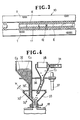
- Figure 1 is a schematic side elevation utilized to show the general construction of an injection molding machine according to a preferred embodiment of the invention;
- Figure 2 is a view analogous to Figure 1 but showing another preferred form of machine according to the invention;
- Figure 3 is a plan view of a slide fastener chain that has been released from the molding machine of Figure 1; and
- Figure 4 is a longitudinal cross-sectional view of a hopper part of the machine of Figure 1.
- Referring first to Figure 3, there is shown a
slide fastener chain 10 which comprises a pair of stringer tapes T, T' each carrying a series of discrete coupling elements E made of thermoplastic material, the coupling elements having a choice of different colors compatible with an article to which the fastener is applied. Thefastener chain 10 is shown disposed immediately after it has been injection-molded and released from the mold, so that the molded elements E are still accompanied byrunners 11 andsprues 12 that will be subsequently removed in a manner hereinafter described. - As shown in Figure 1, a
starting fastener chain 10 devoid of coupling elements E (Figure 3) is passed around aguide roll 13 and into amold 14 comprising astationary die 15 and amovable die 16 in an injection-molding machine generally designated at 17. Themachine 17 per se is of any conventional construction including aheating cylinder 18 operatively associated with the molding dies 15,16. Thefastener chain 10 after having injection-molded thereon series or rows of coupling elements E is withdrawn from themold 14 viafeed rolls guide rolls chamber 24 in a manner well known in the art. - Now, in accordance with the invention there is provided cutting means 25 immediately adjacent to and downstream of the
mold 14 for cutting and removingrunners 11 and sprues 12 (Figure 3) of other debris of the plastic material that have been formed integrally with the coupling elements E. Therunners 11 andsprues 12 thus removed are taken into apelletizer 26 located adjacent to thecutting means 25 and designed to cut them into pellets or chips C1 of a desired size. These pellets or chips C1 are collected in areservoir 27 at the bottom of thepelletizer 26 and from there delivered or recycled to afirst hopper 28 located above theheating cylinder 18, for which purpose there is provided a delivery means 29 comprising afan 30 and aconduit pipe 31 communicating between thefan 30 and thefirst hopper 28. - Parallel with the
first hopper 28 is provided asecond hopper 32 for receiving a supply of colored master chips C2 and colorless slave chips C3, both being thermoplastic. - The first and
second hoppers mixing hopper 33 and have their respective tapered bottomless ends opening into themixing hopper 33 which in turn has its bottom open to communicate with the interior of theheating cylinder 18, the arrangement being that chips C2, C3 are let fall by own gravity throughhopper 33 into thecylinder 18. - It has now been found that the ratio of recycled chips C1 to combined fresh chips C2, C3 is importantly 40―60:60―40 in order to absolutely minimize reduction in physical properties of the resulting element chain E, which properties including mechanical strength and deviations or irregularities in the color of the resulting element chain E. To this end, in the embodiment shown in Figure 1, there are provided shutter means 34 and 35 for first and
second hoppers second hoppers mixing hopper 33 for discharging the chips C1, C2, C3 remaining in therespective hoppers - In the embodiment shown in Figures 2 and 4, the
second hopper 32 for fresh chips C2,C3 has a reduced bottom outlet 32' with a slantedopen end 32" which lies flush with a tapered inner peripheral wall 33' of themixing hopper 33. Theslanted end 32" of thehopper 33 is spaced a predetermined distance or clearance H apart from the peripheral wall 33' of thehopper 32 such that the inventory of fresh chips C2, C3 in thehopper 33 may be maintained constant with respect to a given supply of recycled chips C1. There is provided a verticallymovable bar 36 extending horizontally from avertical column 37 secured to the frame 17' and being adapted to support thereon thesecond hopper 32. Thisbar 36 may be ascended to permit thehopper 32 to detach from themixing hopper 33, or varied in position to adjust the clearance H thereby maintaining controlled inventory of fresh chips C2, C3 with respect to recycled chips C1 depending upon the rate of molding speed of the machine. With thehoppers - An important feature of the invention resides in the concept of removing and pelletizing runners and sprues of the plastic material from the fastener chain immediately upon release from the mold and subsequently recycling pelletized chips for re-use in combination with fresh thermoplastic chips, so that such recycled chips may not undergo any substantial change in their physicochemical properties which would otherwise result in irregular or heterogeneous color distribution of the coupling elements on the finished slide fastener.
Claims (9)
Applications Claiming Priority (4)
| Application Number | Priority Date | Filing Date | Title |
|---|---|---|---|
| JP214828/83 | 1983-11-15 | ||
| JP58214828A JPS60105511A (en) | 1983-11-15 | 1983-11-15 | Method and apparatus for preparing synthetic resin slide fastener chain |
| JP58245936A JPS60141516A (en) | 1983-12-29 | 1983-12-29 | Method of feeding material to thermoplastic synthetic resin molder and apparatus therefor |
| JP245936/83 | 1983-12-29 |
Publications (3)
| Publication Number | Publication Date |
|---|---|
| EP0145971A2 EP0145971A2 (en) | 1985-06-26 |
| EP0145971A3 EP0145971A3 (en) | 1986-03-26 |
| EP0145971B1 true EP0145971B1 (en) | 1988-04-13 |
Family
ID=26520530
Family Applications (1)
| Application Number | Title | Priority Date | Filing Date |
|---|---|---|---|
| EP19840113829 Expired EP0145971B1 (en) | 1983-11-15 | 1984-11-15 | Method of and apparatus for manufacturing molded slide fastener coupling elements |
Country Status (12)
| Country | Link |
|---|---|
| US (2) | US4659301A (en) |
| EP (1) | EP0145971B1 (en) |
| KR (1) | KR870000212B1 (en) |
| AU (1) | AU551885B2 (en) |
| BR (1) | BR8405876A (en) |
| CA (1) | CA1247313A (en) |
| DE (1) | DE3470396D1 (en) |
| ES (2) | ES8506494A1 (en) |
| GB (1) | GB2149716B (en) |
| HK (1) | HK90389A (en) |
| MY (1) | MY101311A (en) |
| SG (1) | SG55789G (en) |
Families Citing this family (12)
| Publication number | Priority date | Publication date | Assignee | Title |
|---|---|---|---|---|
| DE3534403A1 (en) * | 1985-09-27 | 1987-04-02 | Neumuenster Masch App | METHOD AND DEVICE FOR ADDING A FINE DISTRIBUTED COLOR TO A PLASTIC GRANULATE |
| EP0798096A1 (en) * | 1996-03-25 | 1997-10-01 | Sony DADC Austria AG | Method of and apparatus for sprueless molding |
| JPH10243805A (en) * | 1997-03-05 | 1998-09-14 | Ykk Corp | Slide fastener made of synthetic resin |
| US6277314B1 (en) | 1998-02-04 | 2001-08-21 | Flextech Packaging, Ltd. | System and method for producing polymeric film |
| JP4237024B2 (en) * | 2003-10-10 | 2009-03-11 | Sriスポーツ株式会社 | Golf ball manufacturing equipment |
| WO2008036223A2 (en) * | 2006-09-21 | 2008-03-27 | Tyco Healthcare Group Lp | System and method for reclaiming waste from diaper manufacture for the production of medical waste containers |
| CA2937056C (en) | 2014-02-07 | 2021-04-06 | Danmarks Tekniske Universitet | Decoding a combined amplitude modulated and frequency modulated signal |
| WO2019022760A1 (en) * | 2017-07-28 | 2019-01-31 | Hewlett-Packard Development Company, L.P. | Three-dimensional printer with thermal fusion |
| IT201700097253A1 (en) * | 2017-08-30 | 2019-03-02 | Givans Fondi Di Latini Michele & C Sas | PROCEDURE FOR THE REALIZATION OF ECO-SUSTAINABLE PRODUCTS. |
| CN107825674B (en) * | 2017-10-24 | 2020-05-01 | 苏州苏模仪器有限公司 | Packaging plastic hot melting injection molding machine |
| CN110450319A (en) * | 2019-07-22 | 2019-11-15 | 南安市弈诚机械科技有限公司 | A kind of glass fiber plastic particle heat-insulating charger based on formula heating of stirring |
| CN112848090B (en) * | 2021-01-08 | 2022-07-26 | 金华市艺晟工具有限公司 | Injection molding machine equipment of packing |
Family Cites Families (17)
| Publication number | Priority date | Publication date | Assignee | Title |
|---|---|---|---|---|
| US3097395A (en) * | 1963-07-16 | Tadao yoshida | ||
| US3672803A (en) * | 1970-05-13 | 1972-06-27 | Husky Mfg Tool Works Ltd | Scrap grinder for injection-molding machine |
| GB1351119A (en) * | 1970-07-29 | 1974-04-24 | Metal Box Co Ltd | Manufacture of plastic film |
| US3976730A (en) * | 1972-03-23 | 1976-08-24 | Deerfield Plastics Co., Inc. | Method of employing a high percentage of reground thermoplastic scrap resin in an extruder |
| GB1460002A (en) * | 1973-02-22 | 1976-12-31 | Stb Eng Ltd | Systems for the feeding of plastics material to plastics working machines |
| AU6848174A (en) * | 1973-05-31 | 1975-11-06 | Globe Union Inc | Material selector system |
| US4063860A (en) * | 1974-04-15 | 1977-12-20 | Deerfield Plastics Co., Inc. | Apparatus for employing a high percentage of reground thermoplastic scrap resin in an extruder |
| NZ187101A (en) * | 1977-05-04 | 1981-05-01 | Scovill Australia Pty Ltd | Continuous casting of slide fastener interlocking elements onto tape using pair of casting rollers |
| AU520393B2 (en) * | 1977-11-04 | 1982-01-28 | Amoco Corporation | Online film reclaim apparatus and process |
| JPS6110964Y2 (en) * | 1978-07-04 | 1986-04-08 | ||
| US4321027A (en) * | 1979-06-18 | 1982-03-23 | Leesona Corporation | Under the press granulator construction |
| JPS5651326A (en) * | 1979-10-01 | 1981-05-08 | Yoshida Kogyo Kk <Ykk> | Method and apparatus for manufacturing slide fastener with synthetic resin zipper |
| AU547902B2 (en) * | 1980-08-30 | 1985-11-14 | Yoshida Kogyo K.K. | Producing slide fasteners |
| US4340347A (en) * | 1980-12-01 | 1982-07-20 | Robertson Joseph D | Scrap recovery system |
| JPS5991906A (en) * | 1982-11-19 | 1984-05-26 | ワイケイケイ株式会社 | Apparatus for producing slide fastener chain having synthetic resin teeth |
| JPS59101334A (en) * | 1982-11-30 | 1984-06-11 | Yoshida Kogyo Kk <Ykk> | Apparatus for producing slide fastener chain with synthetic teeth |
| AU552900B2 (en) * | 1983-09-09 | 1986-06-26 | Yoshida Kogyo K.K. | Chopping runners and sprues |
-
1984
- 1984-11-08 AU AU35226/84A patent/AU551885B2/en not_active Ceased
- 1984-11-13 ES ES537597A patent/ES8506494A1/en not_active Expired
- 1984-11-13 BR BR8405876A patent/BR8405876A/en not_active IP Right Cessation
- 1984-11-13 ES ES537596A patent/ES8506493A1/en not_active Expired
- 1984-11-14 CA CA000467765A patent/CA1247313A/en not_active Expired
- 1984-11-14 US US06/671,313 patent/US4659301A/en not_active Expired - Lifetime
- 1984-11-14 KR KR1019840007137A patent/KR870000212B1/en not_active IP Right Cessation
- 1984-11-15 DE DE8484113829T patent/DE3470396D1/en not_active Expired
- 1984-11-15 GB GB8428836A patent/GB2149716B/en not_active Expired
- 1984-11-15 EP EP19840113829 patent/EP0145971B1/en not_active Expired
-
1986
- 1986-08-28 US US06/901,362 patent/US4714573A/en not_active Expired - Lifetime
-
1987
- 1987-07-23 MY MYPI87001088A patent/MY101311A/en unknown
-
1989
- 1989-08-25 SG SG55789A patent/SG55789G/en unknown
- 1989-11-16 HK HK90389A patent/HK90389A/en not_active IP Right Cessation
Also Published As
| Publication number | Publication date |
|---|---|
| GB8428836D0 (en) | 1984-12-27 |
| ES537596A0 (en) | 1985-08-16 |
| MY101311A (en) | 1991-09-05 |
| HK90389A (en) | 1989-11-24 |
| KR870000212B1 (en) | 1987-02-17 |
| GB2149716B (en) | 1988-01-20 |
| AU551885B2 (en) | 1986-05-15 |
| BR8405876A (en) | 1985-09-17 |
| ES8506493A1 (en) | 1985-08-16 |
| ES537597A0 (en) | 1985-08-16 |
| EP0145971A3 (en) | 1986-03-26 |
| CA1247313A (en) | 1988-12-28 |
| US4714573A (en) | 1987-12-22 |
| KR850003518A (en) | 1985-06-20 |
| ES8506494A1 (en) | 1985-08-16 |
| DE3470396D1 (en) | 1988-05-19 |
| AU3522684A (en) | 1985-05-23 |
| GB2149716A (en) | 1985-06-19 |
| SG55789G (en) | 1989-12-08 |
| US4659301A (en) | 1987-04-21 |
| EP0145971A2 (en) | 1985-06-26 |
Similar Documents
| Publication | Publication Date | Title |
|---|---|---|
| EP0145971B1 (en) | Method of and apparatus for manufacturing molded slide fastener coupling elements | |
| US2995775A (en) | Injection molding | |
| US5607700A (en) | Synthetic resin pelletizing machine | |
| US20110272847A1 (en) | Device and method for producing molded parts from plasticisable material and from fibrous inserts | |
| CN213055847U (en) | Injection mold convenient to take off material | |
| US20020180090A1 (en) | Methods for manufacturing a module for a modular conveyor belt having a sandwich layer construction | |
| EP0461365B1 (en) | Process and apparatus for feeding a compression mould with extruded plastics | |
| CN207077651U (en) | A kind of HDPE supplying drainages manufacture device systems | |
| CA1058817A (en) | Continuous mold thermo forming | |
| EA004153B1 (en) | Method of manufacturing moulded articles and installation therefor | |
| CN210705720U (en) | Feeding mechanism of polylactic acid plastic tableware forming machine | |
| CN207643636U (en) | A kind of slide fastener processing injection-moulding device | |
| KR20020082313A (en) | system for molding conduit tube using scrapped plastic material | |
| JPS60141516A (en) | Method of feeding material to thermoplastic synthetic resin molder and apparatus therefor | |
| JPS6015116A (en) | Method and apparatus for producing colored synthetic resin molded item | |
| SK280151B6 (en) | Method and devices for producing a moulded plastic article | |
| CN216299952U (en) | Material mixing equipment for injection molding machine | |
| CN214506021U (en) | Auxiliary device for injection molding of new energy automobile connector | |
| CA2054255A1 (en) | Columnar body and process for its manufacture | |
| CN211566731U (en) | Discharging and collecting mechanism of polylactic acid plastic tableware forming machine | |
| DE1529858A1 (en) | Process for the production of thread or fiber reinforced plastic articles | |
| JPH068316A (en) | Vacuum forming method and vacuum forming device | |
| JPS6356044B2 (en) | ||
| KR200258373Y1 (en) | apparatus for molding conduit tube using scrapped plastic material | |
| Kawaguchi et al. | Compression Moulding Synthetic Resin, and Extruder Apparatus for Feeding Synthetic Resin |
Legal Events
| Date | Code | Title | Description |
|---|---|---|---|
| PUAI | Public reference made under article 153(3) epc to a published international application that has entered the european phase |
Free format text: ORIGINAL CODE: 0009012 |
|
| AK | Designated contracting states |
Designated state(s): BE CH DE FR IT LI NL SE |
|
| PUAL | Search report despatched |
Free format text: ORIGINAL CODE: 0009013 |
|
| AK | Designated contracting states |
Kind code of ref document: A3 Designated state(s): BE CH DE FR IT LI NL SE |
|
| 17P | Request for examination filed |
Effective date: 19860625 |
|
| 17Q | First examination report despatched |
Effective date: 19870202 |
|
| GRAA | (expected) grant |
Free format text: ORIGINAL CODE: 0009210 |
|
| AK | Designated contracting states |
Kind code of ref document: B1 Designated state(s): BE CH DE FR IT LI NL SE |
|
| ITF | It: translation for a ep patent filed |
Owner name: JACOBACCI & PERANI S.P.A. |
|
| REF | Corresponds to: |
Ref document number: 3470396 Country of ref document: DE Date of ref document: 19880519 |
|
| ET | Fr: translation filed | ||
| PLBE | No opposition filed within time limit |
Free format text: ORIGINAL CODE: 0009261 |
|
| STAA | Information on the status of an ep patent application or granted ep patent |
Free format text: STATUS: NO OPPOSITION FILED WITHIN TIME LIMIT |
|
| 26N | No opposition filed | ||
| ITTA | It: last paid annual fee | ||
| PGFP | Annual fee paid to national office [announced via postgrant information from national office to epo] |
Ref country code: NL Payment date: 19931130 Year of fee payment: 10 |
|
| PGFP | Annual fee paid to national office [announced via postgrant information from national office to epo] |
Ref country code: SE Payment date: 19940803 Year of fee payment: 11 |
|
| PGFP | Annual fee paid to national office [announced via postgrant information from national office to epo] |
Ref country code: BE Payment date: 19940810 Year of fee payment: 11 |
|
| REG | Reference to a national code |
Ref country code: CH Ref legal event code: PFA Free format text: YKK CORPORATION |
|
| PGFP | Annual fee paid to national office [announced via postgrant information from national office to epo] |
Ref country code: CH Payment date: 19941116 Year of fee payment: 11 |
|
| ITPR | It: changes in ownership of a european patent |
Owner name: CAMBIO RAGIONE SOCIALE;YKK CORPORATION |
|
| REG | Reference to a national code |
Ref country code: FR Ref legal event code: CD |
|
| EAL | Se: european patent in force in sweden |
Ref document number: 84113829.0 |
|
| PG25 | Lapsed in a contracting state [announced via postgrant information from national office to epo] |
Ref country code: NL Effective date: 19950601 |
|
| NLV4 | Nl: lapsed or anulled due to non-payment of the annual fee | ||
| PG25 | Lapsed in a contracting state [announced via postgrant information from national office to epo] |
Ref country code: SE Effective date: 19951116 |
|
| PG25 | Lapsed in a contracting state [announced via postgrant information from national office to epo] |
Ref country code: LI Effective date: 19951130 Ref country code: CH Effective date: 19951130 Ref country code: BE Effective date: 19951130 |
|
| BERE | Be: lapsed |
Owner name: YOSHIDA KOGYO K.K. Effective date: 19951130 |
|
| REG | Reference to a national code |
Ref country code: CH Ref legal event code: PL |
|
| EUG | Se: european patent has lapsed |
Ref document number: 84113829.0 |
|
| PGFP | Annual fee paid to national office [announced via postgrant information from national office to epo] |
Ref country code: FR Payment date: 20031110 Year of fee payment: 20 |
|
| PGFP | Annual fee paid to national office [announced via postgrant information from national office to epo] |
Ref country code: DE Payment date: 20031127 Year of fee payment: 20 |