EP0145937B1 - Optical-fibre connector - Google Patents
Optical-fibre connector Download PDFInfo
- Publication number
- EP0145937B1 EP0145937B1 EP84113433A EP84113433A EP0145937B1 EP 0145937 B1 EP0145937 B1 EP 0145937B1 EP 84113433 A EP84113433 A EP 84113433A EP 84113433 A EP84113433 A EP 84113433A EP 0145937 B1 EP0145937 B1 EP 0145937B1
- Authority
- EP
- European Patent Office
- Prior art keywords
- magnetic field
- fibre
- tube
- connector
- axis
- Prior art date
- Legal status (The legal status is an assumption and is not a legal conclusion. Google has not performed a legal analysis and makes no representation as to the accuracy of the status listed.)
- Expired
Links
Images
Classifications
-
- G—PHYSICS
- G02—OPTICS
- G02B—OPTICAL ELEMENTS, SYSTEMS OR APPARATUS
- G02B6/00—Light guides; Structural details of arrangements comprising light guides and other optical elements, e.g. couplings
- G02B6/24—Coupling light guides
- G02B6/36—Mechanical coupling means
- G02B6/38—Mechanical coupling means having fibre to fibre mating means
- G02B6/3807—Dismountable connectors, i.e. comprising plugs
-
- G—PHYSICS
- G02—OPTICS
- G02B—OPTICAL ELEMENTS, SYSTEMS OR APPARATUS
- G02B6/00—Light guides; Structural details of arrangements comprising light guides and other optical elements, e.g. couplings
- G02B6/24—Coupling light guides
- G02B6/36—Mechanical coupling means
- G02B6/38—Mechanical coupling means having fibre to fibre mating means
- G02B6/3801—Permanent connections, i.e. wherein fibres are kept aligned by mechanical means
- G02B6/3803—Adjustment or alignment devices for alignment prior to splicing
-
- G—PHYSICS
- G02—OPTICS
- G02B—OPTICAL ELEMENTS, SYSTEMS OR APPARATUS
- G02B6/00—Light guides; Structural details of arrangements comprising light guides and other optical elements, e.g. couplings
- G02B6/24—Coupling light guides
- G02B6/36—Mechanical coupling means
- G02B6/38—Mechanical coupling means having fibre to fibre mating means
- G02B6/3801—Permanent connections, i.e. wherein fibres are kept aligned by mechanical means
- G02B6/3806—Semi-permanent connections, i.e. wherein the mechanical means keeping the fibres aligned allow for removal of the fibres
-
- G—PHYSICS
- G02—OPTICS
- G02B—OPTICAL ELEMENTS, SYSTEMS OR APPARATUS
- G02B6/00—Light guides; Structural details of arrangements comprising light guides and other optical elements, e.g. couplings
- G02B6/24—Coupling light guides
- G02B6/36—Mechanical coupling means
- G02B6/38—Mechanical coupling means having fibre to fibre mating means
- G02B6/3807—Dismountable connectors, i.e. comprising plugs
- G02B6/381—Dismountable connectors, i.e. comprising plugs of the ferrule type, e.g. fibre ends embedded in ferrules, connecting a pair of fibres
- G02B6/3818—Dismountable connectors, i.e. comprising plugs of the ferrule type, e.g. fibre ends embedded in ferrules, connecting a pair of fibres of a low-reflection-loss type
- G02B6/382—Dismountable connectors, i.e. comprising plugs of the ferrule type, e.g. fibre ends embedded in ferrules, connecting a pair of fibres of a low-reflection-loss type with index-matching medium between light guides
-
- G—PHYSICS
- G02—OPTICS
- G02B—OPTICAL ELEMENTS, SYSTEMS OR APPARATUS
- G02B6/00—Light guides; Structural details of arrangements comprising light guides and other optical elements, e.g. couplings
- G02B6/24—Coupling light guides
- G02B6/36—Mechanical coupling means
- G02B6/38—Mechanical coupling means having fibre to fibre mating means
- G02B6/3807—Dismountable connectors, i.e. comprising plugs
- G02B6/3873—Connectors using guide surfaces for aligning ferrule ends, e.g. tubes, sleeves, V-grooves, rods, pins, balls
- G02B6/3886—Magnetic means to align ferrule ends
-
- G—PHYSICS
- G02—OPTICS
- G02B—OPTICAL ELEMENTS, SYSTEMS OR APPARATUS
- G02B6/00—Light guides; Structural details of arrangements comprising light guides and other optical elements, e.g. couplings
- G02B6/24—Coupling light guides
- G02B6/26—Optical coupling means
- G02B6/35—Optical coupling means having switching means
- G02B6/3502—Optical coupling means having switching means involving direct waveguide displacement, e.g. cantilever type waveguide displacement involving waveguide bending, or displacing an interposed waveguide between stationary waveguides
-
- G—PHYSICS
- G02—OPTICS
- G02B—OPTICAL ELEMENTS, SYSTEMS OR APPARATUS
- G02B6/00—Light guides; Structural details of arrangements comprising light guides and other optical elements, e.g. couplings
- G02B6/24—Coupling light guides
- G02B6/26—Optical coupling means
- G02B6/35—Optical coupling means having switching means
- G02B6/354—Switching arrangements, i.e. number of input/output ports and interconnection types
- G02B6/3544—2D constellations, i.e. with switching elements and switched beams located in a plane
- G02B6/3548—1xN switch, i.e. one input and a selectable single output of N possible outputs
- G02B6/3552—1x1 switch, e.g. on/off switch
-
- G—PHYSICS
- G02—OPTICS
- G02B—OPTICAL ELEMENTS, SYSTEMS OR APPARATUS
- G02B6/00—Light guides; Structural details of arrangements comprising light guides and other optical elements, e.g. couplings
- G02B6/24—Coupling light guides
- G02B6/26—Optical coupling means
- G02B6/35—Optical coupling means having switching means
- G02B6/3564—Mechanical details of the actuation mechanism associated with the moving element or mounting mechanism details
- G02B6/3568—Mechanical details of the actuation mechanism associated with the moving element or mounting mechanism details characterised by the actuating force
- G02B6/3572—Magnetic force
Description
- The present invention relates to physical carriers for telecommunications systems using light radiation and more particularly it concerns an optical fibre connector.
- As known, one of the main problems to be solved when using optical fibres in transmission systems is that of making good connections between fibres, so as to reduce the coupling losses to a minimum.
- Such losses arise from the displacement, separation and misalignment errors of the two fibre ends to be connected, (i.e. lack of parallelism and lateral axis displacement), as well as from refractive index discontinuity.
- The alignment of the two fibre ends is generally obtained by a sleeve or a V-groove and the fibres are held in position by means of adhesives of elastic elements. Refractive-index matching is obtained by interposing suitable liquids between the two fibre-ends.
- Such sleeve or V guides are suitable for permanent splices, but are ill-suited for connectors, as their structure fragility does not allow the repeated connections and disconnections that a connector generally undergoes.
- Optical fibre connectors exploiting the forces exerted on the fibre ends by a magnetic field are also known.
- Such devices, described for example in U.K. Patent No. 2020055 in the name of same Applicant, or in U.S. Patent No. 4062620 in the name of Telecommunications Radioeiectriques et Tele- phoniques T.R.T., can operate only if the fibre ends are suitably prepared, i.e. by inserting them into small capillary tubes made of ferromagnetic material or by depositing a layer of such material on them by means of an electrochemical process. Yet, these operations can prove particularly difficult owing to reduced fibre size especially when the fibre has already been installed in an underground duct.
- US-A-4 384 761 describes a switch in which the cantilevered end of an optical fibre is repositioned by buoyancy effects created by a ferromagnetic fluid acted upon by a magnetic field. V-shaped grooves are used to ensure precise alignment of the fibre end.
- The above disadvantages are overcome by the optical-fibre connector of the present invention, which allows optical fibres to be connected without end preparation and which ensures their alignment without the use of mechanical elements having high accuracy or adjustment requirements.
- Alignment is obtained by exploiting the special properties of the so-called ferromagnetic fluids. These fluids are colloids in which very small ferromagnetic particles are suspended in a carrier liquid. The suspension is stable, even though particle density is higher than liquid density, because the particle continuously strikes the carrier liquid molecules in random thermal agitation. If the thermal energy is equal to or higher than the gravitational energy necessary to raise the particles to the height that they have attained in the vessel containing the fluid and if the particle dimensions do not exceed a few nanometers the suspension is stable. The aggregation between the particles, due to magnetic and van der Waals forces is avoided by coating each particle with a molecular film of a surfactant, which acts as an elastic surface.
- The application of a magnetic field to a ferromagnetic fluid causes a volume force. A force proportional to the product of the absolute value of the magnetic momentum and the space gradient of the modulo of the magnetic field acts on each magnetic particle. More particularly, in a ferromagnetic fluid at rest the sum of the energy due to hydrostatic pressure and the magnetic energy is constant.
- The present invention provides an optical fibre connector containing elements capable of generating a magnetic field in which fibre end alignment is achieved by means of the magnetic field and in which refractive index matching between the fibre ends is accomplished by means of a matching liquid, characterized by a cylindrical tube of non-ferromagnetic material whose internal diameter exceeds that of the fibres to be connected and into which the fibre ends have been inserted together with a ferromagnetic fluid after the fibre end faces have been covered with said index-matching liquid, the elements being positioned about the tube so as to be able to generate a magnetic field with an intensity minimum coinciding with said tube's axis and whose intensity increases with radial distance from the axis, the connector being such that the opposed fibre end faces are aligned solely by the effect of the ferromagnetic fluid responding to the magnetic field.
- The foregoing and other characteristics of the present invention will be made clearer by the following description of a preferred embodiment thereof, shown on the accompanying drawing and given by way of example.
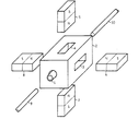
- Reference 1 denotes a small tube made of non-ferromagnetic material, e.g. glass, with the inner diameter greater than the external diameter of optical fibres. The small tube is housed in a cylindrical hole made in a block of
non-ferromagnetic material 2, forming the connector body. - Four cavities are made in the block in symmetrical positions around the hole (3 and 4 are shown in the drawing) to house four
magnetic bars -
Fibre ends 9 and 10 are then inserted into the small tube till they contact, after placing a few drops of refractive-index matching liquid on the end faces. - A small quantity of ferromagnetic fluid is then injected, e.g. by a syringe, inside the small tube. This fluid flows towards the middle zone, where the magnetic field is strongest. Meanwhile hydrostatic fluid pressure inside the fluid becomes such as to maintain the sum of pressure and magnetic field energies constant. An axial region is thus obtained coincident with that where magnetic-field energy is maximum (minimum intensity) and where hydrostatic pressure is minimum.
- The optical fibres and the index-matching liquid are consequently drawn into the axial region where the pressure is minimum, and are aligned. To obtain maximum light-energy transfer the liquid interposed between the fibres ends ought not to be miscible with the magnetic fluid. This ensures that opaque ferromagnetic particles, which have moved away from the small cylinder axis due to a ferromagnetic field effect, cannot be interposed between the end faces of the fibres.
- As an example if the fibre ends to be connected have a length of about 30 mm inside the small tube, then their weight would be about 0.8 mg. The buoyant force due to fluid contributes to suspend the ends for about a third of their weight, for this reason only about 0.5 mg of the fibre weight needs to be counterbalanced by the fluid force due to electromagnetic field.
- In case of a fibre having a diameter of 120 pm, inserted a distance of 30 mm into the small tube, the surface on which the magnetic force acts is about 3.6 mm2, and hence the force is 2 - 3.6=7.2 g, considerably higher than the value of 0.5 mg necessary to raise the fibre.
- It is clear that what is described has been given only by way of a non-limiting example. Variations and modifications to the above embodiments may of course be made without departing from the scope of the invention.
- For example, the magnetic field could be generated by electro-magnets and not by permanent magnets. In addition, the connector shown in the drawing can be housed in a container equipped at the ends with suitable devices (e.g. a gland) suited to fix and protect the optical fibre ends which are normally within an optical cable.
Claims (3)
Applications Claiming Priority (2)
| Application Number | Priority Date | Filing Date | Title |
|---|---|---|---|
| IT6817383 | 1983-11-10 | ||
| IT68173/83A IT1205397B (en) | 1983-11-10 | 1983-11-10 | CONNECTOR FOR OPTICAL FIBERS |
Publications (2)
| Publication Number | Publication Date |
|---|---|
| EP0145937A1 EP0145937A1 (en) | 1985-06-26 |
| EP0145937B1 true EP0145937B1 (en) | 1987-09-09 |
Family
ID=11308329
Family Applications (1)
| Application Number | Title | Priority Date | Filing Date |
|---|---|---|---|
| EP84113433A Expired EP0145937B1 (en) | 1983-11-10 | 1984-11-07 | Optical-fibre connector |
Country Status (6)
| Country | Link |
|---|---|
| US (1) | US4636032A (en) |
| EP (1) | EP0145937B1 (en) |
| JP (1) | JPS60117204A (en) |
| CA (1) | CA1249465A (en) |
| DE (2) | DE145937T1 (en) |
| IT (1) | IT1205397B (en) |
Families Citing this family (9)
| Publication number | Priority date | Publication date | Assignee | Title |
|---|---|---|---|---|
| DE3534017A1 (en) * | 1985-09-24 | 1987-03-26 | Siemens Ag | METHOD FOR COUPLING A LASER DIODE TO A MONOMODE LIGHT WAVE GUIDE, AND AN ARRANGEMENT OF A LASER DIODE AND A LIGHT WAVE GUIDE COUPLED TO IT |
| DE3613345A1 (en) * | 1986-04-19 | 1987-10-22 | Philips Patentverwaltung | DEVICE FOR PAIRING THE ENDS OF TWO GROUPS OF FIBER-SHAPED FIBER-WAVE GUIDES IN PAIRS |
| US5000532A (en) * | 1988-08-02 | 1991-03-19 | At&T Bell Laboratories | Optical fiber switch |
| US4896937A (en) * | 1988-08-02 | 1990-01-30 | American Telephone And Telegraph Company, At&T Bell Laboratories | Optical fiber switch |
| US6102582A (en) * | 1998-09-21 | 2000-08-15 | Lucent Technologies Inc. | Article comprising controllable optical connectors |
| US8781273B2 (en) | 2010-12-07 | 2014-07-15 | Corning Cable Systems Llc | Ferrule assemblies, connector assemblies, and optical couplings having coded magnetic arrays |
| US8774577B2 (en) | 2010-12-07 | 2014-07-08 | Corning Cable Systems Llc | Optical couplings having coded magnetic arrays and devices incorporating the same |
| US8734024B2 (en) | 2011-11-28 | 2014-05-27 | Corning Cable Systems Llc | Optical couplings having a coded magnetic array, and connector assemblies and electronic devices having the same |
| CN107076937B (en) | 2014-09-23 | 2019-11-08 | 康宁光电通信有限责任公司 | Optical conenctor and complementary optical jack with magnetic attachment |
Family Cites Families (6)
| Publication number | Priority date | Publication date | Assignee | Title |
|---|---|---|---|---|
| AT325326B (en) * | 1972-07-10 | 1975-10-10 | Siemens Ag | CONNECTING PLUG FOR OPTICAL FIBERS AND METHOD FOR ESTABLISHING FIXED CONNECTIONS USING A CONNECTING PLUG |
| FR2305746A1 (en) * | 1975-03-25 | 1976-10-22 | Trt Telecom Radio Electr | CONNECTOR FOR OPTICAL FIBERS |
| DE2645991A1 (en) * | 1976-10-12 | 1978-04-13 | Siemens Ag | Photoconductor cable connection with magnetic coupling - has alignment and centering of individual strands performed by guide grooves |
| IT1107327B (en) * | 1978-04-26 | 1985-11-25 | Cselt Centro Studi Lab Telecom | MAGNETIC ONLECTOR FOR OPTICAL CABLES |
| US4384761A (en) * | 1980-06-30 | 1983-05-24 | International Business Machines Corporation | Ferrofluid optical switches |
| US4448483A (en) * | 1981-08-20 | 1984-05-15 | Trw Inc. | Optical fiber connectors with automatic supply of index matching fluid and reservoirs for same |
-
1983
- 1983-11-10 IT IT68173/83A patent/IT1205397B/en active
-
1984
- 1984-10-31 CA CA000466724A patent/CA1249465A/en not_active Expired
- 1984-11-06 JP JP59232550A patent/JPS60117204A/en active Granted
- 1984-11-07 DE DE198484113433T patent/DE145937T1/en active Pending
- 1984-11-07 EP EP84113433A patent/EP0145937B1/en not_active Expired
- 1984-11-07 DE DE8484113433T patent/DE3466082D1/en not_active Expired
- 1984-11-08 US US06/669,628 patent/US4636032A/en not_active Expired - Fee Related
Also Published As
| Publication number | Publication date |
|---|---|
| CA1249465A (en) | 1989-01-31 |
| US4636032A (en) | 1987-01-13 |
| EP0145937A1 (en) | 1985-06-26 |
| JPS60117204A (en) | 1985-06-24 |
| DE145937T1 (en) | 1985-11-21 |
| IT1205397B (en) | 1989-03-15 |
| JPS6211323B2 (en) | 1987-03-12 |
| IT8368173A0 (en) | 1983-11-10 |
| DE3466082D1 (en) | 1987-10-15 |
Similar Documents
| Publication | Publication Date | Title |
|---|---|---|
| US4062620A (en) | Device for connecting optical fibers | |
| EP0145937B1 (en) | Optical-fibre connector | |
| US4384761A (en) | Ferrofluid optical switches | |
| EP0653656B1 (en) | Ferrofluid switch for a light pipe | |
| US4934785A (en) | Optical fiber connector | |
| US4474423A (en) | Automatic alignment apparatus for optical fiber splicing | |
| US3960531A (en) | Method and apparatus for splicing optical fibers | |
| US4545644A (en) | Optical fiber connector and articles connected therewith | |
| US4850670A (en) | Optical fiber connector comprising drawn glass tubes | |
| US10120147B2 (en) | Method of fabricating optical communication apparatus, optical connecting part, optical communication apparatus | |
| CA1113760A (en) | Magnetic connector for optical cables | |
| IE41880B1 (en) | A connector for optical fibres | |
| JP2024019552A (en) | Optical connectors and optical connection structures | |
| KR101602081B1 (en) | Optical fiber having core-to-core alignment | |
| CN111123443A (en) | Structure for realizing optical coaxiality by utilizing wedge angle sheet and application thereof | |
| US4244681A (en) | Magnetic fiber optic casting apparatus | |
| CN211698280U (en) | Structure for realizing light coaxiality by utilizing wedge angle sheet, collimator and photoelectric detector | |
| EP0927894A1 (en) | Fiber-to-multiple-fiber magnetic switch | |
| JP4689053B2 (en) | Method and apparatus for aligning a waveguide to a device | |
| CN111964662A (en) | Photoelectric integrated small-sized double-shaft fiber-optic gyroscope | |
| WO2024101389A1 (en) | Optical connector, optical module, plug, and connection method | |
| JPH11249038A (en) | Optical fiber switch | |
| SU1303825A1 (en) | Device for measuring object slope and direction of inclination | |
| Vanda et al. | Optical properties of microstructured fibre tuned by filling with magnetic liquids | |
| JPS6142607A (en) | Optical connector |
Legal Events
| Date | Code | Title | Description |
|---|---|---|---|
| PUAI | Public reference made under article 153(3) epc to a published international application that has entered the european phase |
Free format text: ORIGINAL CODE: 0009012 |
|
| AK | Designated contracting states |
Designated state(s): DE FR GB NL |
|
| 17P | Request for examination filed |
Effective date: 19850704 |
|
| EL | Fr: translation of claims filed | ||
| DET | De: translation of patent claims | ||
| TCNL | Nl: translation of patent claims filed | ||
| 17Q | First examination report despatched |
Effective date: 19860909 |
|
| GRAA | (expected) grant |
Free format text: ORIGINAL CODE: 0009210 |
|
| AK | Designated contracting states |
Kind code of ref document: B1 Designated state(s): DE FR GB NL |
|
| REF | Corresponds to: |
Ref document number: 3466082 Country of ref document: DE Date of ref document: 19871015 |
|
| ET | Fr: translation filed | ||
| PGFP | Annual fee paid to national office [announced via postgrant information from national office to epo] |
Ref country code: NL Payment date: 19871130 Year of fee payment: 4 |
|
| PLBE | No opposition filed within time limit |
Free format text: ORIGINAL CODE: 0009261 |
|
| STAA | Information on the status of an ep patent application or granted ep patent |
Free format text: STATUS: NO OPPOSITION FILED WITHIN TIME LIMIT |
|
| 26N | No opposition filed | ||
| PG25 | Lapsed in a contracting state [announced via postgrant information from national office to epo] |
Ref country code: GB Effective date: 19891107 |
|
| PG25 | Lapsed in a contracting state [announced via postgrant information from national office to epo] |
Ref country code: NL Effective date: 19900601 |
|
| GBPC | Gb: european patent ceased through non-payment of renewal fee | ||
| NLV4 | Nl: lapsed or anulled due to non-payment of the annual fee | ||
| PG25 | Lapsed in a contracting state [announced via postgrant information from national office to epo] |
Ref country code: FR Effective date: 19900731 |
|
| PG25 | Lapsed in a contracting state [announced via postgrant information from national office to epo] |
Ref country code: DE Effective date: 19900801 |
|
| REG | Reference to a national code |
Ref country code: FR Ref legal event code: ST |