EP0145839B1 - Device for extruding flowable substances - Google Patents
Device for extruding flowable substances Download PDFInfo
- Publication number
- EP0145839B1 EP0145839B1 EP84109702A EP84109702A EP0145839B1 EP 0145839 B1 EP0145839 B1 EP 0145839B1 EP 84109702 A EP84109702 A EP 84109702A EP 84109702 A EP84109702 A EP 84109702A EP 0145839 B1 EP0145839 B1 EP 0145839B1
- Authority
- EP
- European Patent Office
- Prior art keywords
- nozzle bar
- groove
- inner container
- openings
- container
- Prior art date
- Legal status (The legal status is an assumption and is not a legal conclusion. Google has not performed a legal analysis and makes no representation as to the accuracy of the status listed.)
- Expired
Links
- 239000000126 substance Substances 0.000 title claims description 25
- 230000009969 flowable effect Effects 0.000 title claims description 7
- 238000010438 heat treatment Methods 0.000 claims description 10
- 238000001816 cooling Methods 0.000 claims description 9
- 238000005496 tempering Methods 0.000 claims description 4
- 238000003780 insertion Methods 0.000 claims description 3
- 230000037431 insertion Effects 0.000 claims description 3
- 239000011345 viscous material Substances 0.000 description 13
- 238000010276 construction Methods 0.000 description 10
- 238000013461 design Methods 0.000 description 4
- 238000001125 extrusion Methods 0.000 description 3
- 239000000945 filler Substances 0.000 description 3
- 239000000463 material Substances 0.000 description 3
- 230000000694 effects Effects 0.000 description 2
- 238000005259 measurement Methods 0.000 description 2
- 230000002411 adverse Effects 0.000 description 1
- 230000009286 beneficial effect Effects 0.000 description 1
- 230000001276 controlling effect Effects 0.000 description 1
- 230000001419 dependent effect Effects 0.000 description 1
- 238000005485 electric heating Methods 0.000 description 1
- 238000009434 installation Methods 0.000 description 1
- 238000004519 manufacturing process Methods 0.000 description 1
- 238000012544 monitoring process Methods 0.000 description 1
- 238000012545 processing Methods 0.000 description 1
- 230000001105 regulatory effect Effects 0.000 description 1
- 239000000523 sample Substances 0.000 description 1
- 238000007789 sealing Methods 0.000 description 1
Images


Classifications
-
- B—PERFORMING OPERATIONS; TRANSPORTING
- B01—PHYSICAL OR CHEMICAL PROCESSES OR APPARATUS IN GENERAL
- B01J—CHEMICAL OR PHYSICAL PROCESSES, e.g. CATALYSIS OR COLLOID CHEMISTRY; THEIR RELEVANT APPARATUS
- B01J2/00—Processes or devices for granulating materials, e.g. fertilisers in general; Rendering particulate materials free flowing in general, e.g. making them hydrophobic
- B01J2/20—Processes or devices for granulating materials, e.g. fertilisers in general; Rendering particulate materials free flowing in general, e.g. making them hydrophobic by expressing the material, e.g. through sieves and fragmenting the extruded length
-
- B—PERFORMING OPERATIONS; TRANSPORTING
- B29—WORKING OF PLASTICS; WORKING OF SUBSTANCES IN A PLASTIC STATE IN GENERAL
- B29B—PREPARATION OR PRETREATMENT OF THE MATERIAL TO BE SHAPED; MAKING GRANULES OR PREFORMS; RECOVERY OF PLASTICS OR OTHER CONSTITUENTS OF WASTE MATERIAL CONTAINING PLASTICS
- B29B9/00—Making granules
- B29B9/10—Making granules by moulding the material, i.e. treating it in the molten state
-
- B—PERFORMING OPERATIONS; TRANSPORTING
- B29—WORKING OF PLASTICS; WORKING OF SUBSTANCES IN A PLASTIC STATE IN GENERAL
- B29C—SHAPING OR JOINING OF PLASTICS; SHAPING OF MATERIAL IN A PLASTIC STATE, NOT OTHERWISE PROVIDED FOR; AFTER-TREATMENT OF THE SHAPED PRODUCTS, e.g. REPAIRING
- B29C48/00—Extrusion moulding, i.e. expressing the moulding material through a die or nozzle which imparts the desired form; Apparatus therefor
Definitions
- the invention concerns a device for extruding flowable substances from two cylindrical containers, of which the first is provided with openings on its periphery and is rotatable about the outerwall of a cylindrical inner container to which the substance to be extruded is axially fed and, through a row of openings which, during relative rotation of the two cylindrical containers coincide cyclically with the openings of the outer container, falls in drop form onto a conveyor or cooling belt, which is arranged below it, and solidifies or gelatinizes there.
- the invention consists, with a construction of the above-noted type, in that the row of openings are provided in a nozzle bar which can be attached to the periphery of the inner container.
- This design has the advantage that various nozzle bars can be provided whose form is different in each case and is suitable for various applications. The adaptability to various materials is thus increased without the cost of construction for a so-called rotor drop shaper becoming too great.
- the nozzle bar is formed straight and inserted parallel to the axis of rotation of the cylindrical containers, which can be accomplished if the nozzle bar is inserted in a groove on the inner container.
- the groove has parallel walls, so that the bar is led in radial direction, freely moving on the inner container and is held by the outer cylinder which surrounds the inner container.
- the nozzle bar is pressed, with this design, under the pressure of the substance to be extruded, against the outer container and in this way gives a tight and good guide as well as a sufficient stripping effect.
- This embodiment is particularly suitable for low-viscous substances, with which the extrusion pressure can still be maintained relatively low, so that the contact pressure of the nozzle bar against the rotating cylinder, which is located on the outside, cannot lead to an increased wear, not to mention to a deformation of the outer cylinder.
- a construction has proven itself advantageous with which the nozzle bar is axially inserted, in a form-locking manner, into a guide on the inner container.
- This groove which serves to guide the nozzle bar, can, for example, have a T-shaped cross-section to which the outer shape of the nozzle bar is adapted.
- the nozzle bar itself is heated or cooled, so that, in addition to the tempering device already present in the inner container for the substance to be extruded, yet another tempering device is provided in the area in which the substance is pressed outward through relatively small openings.
- the nozzle bar can have a heating or cooling coil which for practical purposes is placed on both sides of the row of openings, so that a very sensitive temperature control is possible if this additional heating or cooling coil is regulated in its temperature, which can be easily accomplished.
- this additional heating or cooling coil is regulated in its temperature, which can be easily accomplished.
- the outer container is made so that it can be easily removed axially from the inner container, which can be attained by a suitable support structure on the side turned away from the rotating drive.
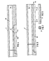
- a so-called rotor drop shaper is schematically illustrated whose actual part, made for dropping flowable substances, consists of an outer cylindrical container 1, provided with openings 2 on its periphery, in tubular shape, and of an inner container 3, which is provided inside this cylindrical container 1, into which the substance to be dropped is axially fed in direction of the arrow 4 and radially pressed out through a row of openings, which will be described in detail later, and which, in each case, coincide cyclically on the downward turned side with the openings 2 of the outer container 1, which turns relative to the inner container 3.
- a conveyor or cooling belt 5 is provided which runs vertically to the drawing plane in the representation of Fig.
- both the width of the conveyor or cooling belt 5 and the length of the two cylindrical containers 1 and 3 are shown shortened; the width of belt 5 and the corresponding length of the containers 1 and 3 can be chosen according to type of use and desired production. With most rotor drop shapers, this measurement is approximately one meter.
- the outer cylindrical container 1 is connected torsion-resistant at both its ends with flanges 6, 6', whereby flange 6 is fixed by way of a support 7, which is not shown in greater detail, and connected torsion-resistant, by way of an adjusting wedge 8' or the like, with a driving part 8 which, for its part, is rigidly connected with a gear wheel 9, driven in a manner which is not shown.
- flange 6' is pivoted in a bearing part 10, which is supported in fixed bracked plates 11 or 12, just as the pivot and driving part 8, so that the rotor drop shaper assumes a defined position above the cooling or conveyor belt 5.
- the relative position of the inner container 3 to the conveyor or cooling belt 5 can be adjusted by way of a hand lever 13 with which the inner container can be tilted vis-a-vis its base plate 11.
- the set position can be read by way of an indicator 13', firmly connected with lever 13, on a scale 14 which is permanently mounted on the base plate 11.
- the substance, for the first part, but also a heating medium, for the second part is fed to the interior of the inner container 3 in a direction of the arrow 4 through the conduit 15; said heating medium can again be carried off by a connection, which is not shown, on the other side.
- the heating medium is described in greater detail in the following.
- the outer container 1 can be axially removed from the inner container 3.
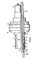
- Fig. 2 and Fig. 3 show that the inner container 3 or 3' of the rotor drop shaper is provided with an axially running feed bore 20 for the material to be extruded, into which the substance is fed in direction of the arrow 4 of Fig. 1. This occurs under pressure.
- the inner container 3 or 3' is, moreover, also provided with two ducts 21, running parallel to the bore 20, in which the heating medium, preferably thermal oil, which is fed through the connection 15, is led.
- This heating medium is tempered by a suitable control device, situated on the outside.
- the substance to be extruded reaches, by way of several bores 22, into a duct 23, which runs parallel to the axis 19, and which is always open to the outside and closed by the outer cylindrical container 1 which is rotatable relative to the inner container 3.
- the tempered substance which is under pressure, enters, through a row of openings 24 in a nozzle bar 25, into a downward open groove 26 of the nozzle bar 25.
- the openings 24 and their groove 26 coincide cyclically with the openings 2, guided past them, of the outer container 1, so that the substance, which is also still under a certain pressure in the groove 26, is pressed out through the openings 2 and falls in form of drops 27 (Fig. 1) onto the cooling or conveyor belt 5 located below it. These drops subsequently solidify or gelatinize and can then be further processed.
- duct 23 leads into a groove 28 with T-shaped cross-section, to which the cross-section of the nozzle bar 25 is also adapted.
- the nozzle bar is-after axial removal of the outer container 1-axially inserted into the T-shaped groove.
- the device can be used after mounting the outer container 1. It has the advantage that the nozzle bar 25 is supported by its T-shaped form with the stops 29, which point to both sides, on the corresponding stops 28a of the groove 28. The extruding pressure used when dropping high-viscous substances, and the thereby resulting forces on the nozzle bar are thus absorbed by the inner container 3'. Deformation forces are not exerted on the outer container 1.
- the measurement of the nozzle bar are, of course, chosen in such a way that the nozzle bar fills the cross-section formed by the groove 28.
- the nozzle bar 25 is, for this purpose, also made slightly spherical at its underside 25', with a radius which is adjusted to the inner diameter of the container 1.
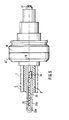
- Fig. 3 The construction of Fig. 3 is suitable for extruding low-viscous substances.
- the nozzle bar 25a has two side walls 30, running parallel to one another, which are guided along corresponding parallel walls of the groove 28b.
- the nozzle bar 25a is, therefore, pressed against the inner side of the outer container 1 by the pressure of the medium to be extruded, so that a very good sealing effect results between nozzle bar, whose underside 25a' is spherical again, and the outer container 1.
- the pressures to be used are not so high that damage to the outer container 1 must be feared.
- nozzle bar 25 or 25a the inner containers 3 or 3' can also be formed differently.
- Fig. 4 shows the inner container 3 of Fig. 3, which has a groove 28a here with parallel walls; the nozzle bar 25a of Fig. 3 is radially inserted from the outside into this groove 28a. After mounting the outer cylindrical container 1, nozzle bar 25a is secured in the inner container 3.
- groove 28 is continued axially up to the right front end 3'a of the inner container 3'.
- the front end 3'a of the inner container 3' and the front end 3a of the inner container 3 shown in Fig. 4 are arranged laterally inverted compared to Fig. 1.
- the front end 3a or 3'a always points, after installation in the rotor drop shaper of Fig. 1, to the left in direction to the two female screws 17 and 18.
- the insertion of the nozzle bar 25 of Fig. 2a also takes place from this side.
- the nozzle bar 25 is inserted in direction of the arrow 40 in Fig. 5. After insertion, it is secured in its position in that the filler 31 is also added in direction of the arrow 30 and then, as schematically indicated by arrows 32, secured in its axial position by screwing.
- a nozzle bar 25b which has a T-shaped cross-section and is guided in a corresponding groove 28 in the inner container 3', is axially inserted into the inner container 3'.
- nozzle bar 25b has an electric heating coil 33, which is placed on both sides of the row of openings 24 in the area of the upper side of nozzle bar 25b and is provided, by a connecting piece 34, with connecting pipes 35, 'which are led outward by way of a pipe 36 and which are provided there with a control mechanism, which is not illustrated, for monitoring and controlling the temperature in the area of the nozzle bar 25b.
- the connecting piece 34 can also contain suitable thermometer probes.
- the heating coil 33 is laid equidistantly on both sides of the openings 24 and is turned U-shaped in the end area 33a. This design enables a very sensitive temperature control for the substances to be extruded directly in the area of the row of openings 24. Even the nozzle bar 25b can be, moreover, axially removed from the inner container 3' and, if necessary, replaced. As a result of the temperature influences, which are possible, until just before the discharge of the drops, a trouble- free operation can also be maintained for flowable substances whose viscosity is very temperature dependent.
Landscapes
- Chemical & Material Sciences (AREA)
- Engineering & Computer Science (AREA)
- Mechanical Engineering (AREA)
- Organic Chemistry (AREA)
- Chemical Kinetics & Catalysis (AREA)
- Extrusion Moulding Of Plastics Or The Like (AREA)
- Coating Apparatus (AREA)
- Processing And Handling Of Plastics And Other Materials For Molding In General (AREA)
- Glanulating (AREA)
Description
- The invention concerns a device for extruding flowable substances from two cylindrical containers, of which the first is provided with openings on its periphery and is rotatable about the outerwall of a cylindrical inner container to which the substance to be extruded is axially fed and, through a row of openings which, during relative rotation of the two cylindrical containers coincide cyclically with the openings of the outer container, falls in drop form onto a conveyor or cooling belt, which is arranged below it, and solidifies or gelatinizes there.
- Devices of this type are known (EP-A 12 192). The row of openings, provided with the known constructions in the there stationary inner container, has specific dimensions, so that it becomes necessary in each case for dropping various substances to always select the temperature, necessary for dropping, of the substance and therewith its viscosity in such a way that the dropping takes place in the desired manner. It was found that the use of known extrusion devices of the previously noted type is somewhat limited due to this design, because the temperature cannot always be set with all substances in such a way that the desired viscosity is attained, which yield the desired drop-shape with the opening dimensions, given in advance, for passage of the substance.
- It is, therefore, the object of the invention, with devices of the above-noted type, to find an adapting possibility, which goes beyond this, to the material to be dropped in order to increase the range of application of devices for extruding flowable substances with two cylinders which can be turned relative to one another.
- The invention consists, with a construction of the above-noted type, in that the row of openings are provided in a nozzle bar which can be attached to the periphery of the inner container. This design has the advantage that various nozzle bars can be provided whose form is different in each case and is suitable for various applications. The adaptability to various materials is thus increased without the cost of construction for a so-called rotor drop shaper becoming too great.
- It is practical if the nozzle bar is formed straight and inserted parallel to the axis of rotation of the cylindrical containers, which can be accomplished if the nozzle bar is inserted in a groove on the inner container.
- It is thereby advantageous for certain areas of application if the groove has parallel walls, so that the bar is led in radial direction, freely moving on the inner container and is held by the outer cylinder which surrounds the inner container. The nozzle bar is pressed, with this design, under the pressure of the substance to be extruded, against the outer container and in this way gives a tight and good guide as well as a sufficient stripping effect. This embodiment is particularly suitable for low-viscous substances, with which the extrusion pressure can still be maintained relatively low, so that the contact pressure of the nozzle bar against the rotating cylinder, which is located on the outside, cannot lead to an increased wear, not to mention to a deformation of the outer cylinder.
- For use with high-viscous substances, on the other hand, a construction has proven itself advantageous with which the nozzle bar is axially inserted, in a form-locking manner, into a guide on the inner container. This groove, which serves to guide the nozzle bar, can, for example, have a T-shaped cross-section to which the outer shape of the nozzle bar is adapted. With this embodiment, the considerably higher pressure, which is used for extruding the high-viscous substances, and the forces exerted thereby on the nozzle bar are absorbed by the inner container. The nozzle bar is therefore, not pressed with too great a force against the inner wall of the outer cylindrical container, so that the operability is not adversely affected.
- In order to attain a fine-tuning of the viscosity of the substances to be extruded, it is, moreover, advantageous if the nozzle bar itself is heated or cooled, so that, in addition to the tempering device already present in the inner container for the substance to be extruded, yet another tempering device is provided in the area in which the substance is pressed outward through relatively small openings.
- For this purpose, the nozzle bar can have a heating or cooling coil which for practical purposes is placed on both sides of the row of openings, so that a very sensitive temperature control is possible if this additional heating or cooling coil is regulated in its temperature, which can be easily accomplished. In this way, the substance to be extruded can still be exactly tempered until shortly before its discharge, so that excellent dropping results can be achieved with this new embodiment.
- In order to attach the nozzle bar to the inner container, be it, therefore, in order to press it radially from the outside into the groove, as is the case with low-viscous substances, be it, in order to insert it axially into the groove, which is furnished with form-locking guides, as is provided during processing of high-viscous substances, it is very beneficial if the outer container is made so that it can be easily removed axially from the inner container, which can be attained by a suitable support structure on the side turned away from the rotating drive.
- Additional features and advantages of the invention as defined in the claims are shown in the embodiments of the invention, which are explained in the following description and illustrated with reference to the drawings, showing:
- Fig. 1 a schematic view of a new device, made in the form of a so-called rotor drop shaper, for extruding flowable substances,
- Fig. 2 the schematic section through this rotor drop shaper cut in direction of the line II-II, however, without the parts still present behind the sectional plane, in a construction which is used for dropping high-viscous substances,
- Fig. 2a a perspective partial representation of the nozzle bar inserted into the inner container of Fig. 2,
- Fig. 3 the section similar to Fig. 2, however, with a construction which is used for dropping low-viscous substances,
- Fig. 3a a perspective partial view of the nozzle bar inserted into the inner container of Fig. 3,
- Fig. 4 a schematic longitudinal section through the inner container of the rotor drop shaper of Fig. 1 with a construction for low-viscous substances in accordance with Fig. 3,
- Fig. 5 the inner container of the rotor drop shaper of Fig. 1, however, for a construction for high-viscous substances in accordance with Fig. 2,
- Fig. 6 the filler which can be axially inserted into the inner container of Fig. 5,
- Fig. 7 the cross-section of the filler of Fig. 6,
- Fig. 8 a schematic partial section through a rotor drop shaper similar to Fig. 1, however, with an inserted nozzle bar with an additional heating, and
- Fig. 9 the top view of the nozzle bar of Fig. 8 in a partial section through the rotor drop shaper of Fig. 8.
- In Fig. 1, a so-called rotor drop shaper is schematically illustrated whose actual part, made for dropping flowable substances, consists of an outer
cylindrical container 1, provided withopenings 2 on its periphery, in tubular shape, and of aninner container 3, which is provided inside thiscylindrical container 1, into which the substance to be dropped is axially fed in direction of thearrow 4 and radially pressed out through a row of openings, which will be described in detail later, and which, in each case, coincide cyclically on the downward turned side with theopenings 2 of theouter container 1, which turns relative to theinner container 3. Below the two counter-rotatingcylindrical containers cooling belt 5 is provided which runs vertically to the drawing plane in the representation of Fig. 1 and which is led through by guide devices below the twocontainers cooling belt 5 and the length of the twocylindrical containers belt 5 and the corresponding length of thecontainers - The outer
cylindrical container 1 is connected torsion-resistant at both its ends withflanges 6, 6', wherebyflange 6 is fixed by way of a support 7, which is not shown in greater detail, and connected torsion-resistant, by way of an adjusting wedge 8' or the like, with a driving part 8 which, for its part, is rigidly connected with a gear wheel 9, driven in a manner which is not shown. In a similar manner, flange 6' is pivoted in abearing part 10, which is supported in fixed bracked plates 11 or 12, just as the pivot and driving part 8, so that the rotor drop shaper assumes a defined position above the cooling orconveyor belt 5. The relative position of theinner container 3 to the conveyor orcooling belt 5 can be adjusted by way of ahand lever 13 with which the inner container can be tilted vis-a-vis its base plate 11. The set position can be read by way of an indicator 13', firmly connected withlever 13, on ascale 14 which is permanently mounted on the base plate 11. The substance, for the first part, but also a heating medium, for the second part, is fed to the interior of theinner container 3 in a direction of thearrow 4 through theconduit 15; said heating medium can again be carried off by a connection, which is not shown, on the other side. The heating medium is described in greater detail in the following. For reasons also to be clarified later, theouter container 1 can be axially removed from theinner container 3. This is accomplished in that, after unscrewing theclamping bolts bearing part 10 and the flange 6', can be removed toward the left with thecontainer 1 in direction of theaxis 19 of the rotor drop shaper. - The inner structure of the actual part serving as the dropper becomes clear from Fig. 2 and Fig. 3. Fig. 2 and Fig. 3 show that the
inner container 3 or 3' of the rotor drop shaper is provided with an axially runningfeed bore 20 for the material to be extruded, into which the substance is fed in direction of thearrow 4 of Fig. 1. This occurs under pressure. Theinner container 3 or 3' is, moreover, also provided with twoducts 21, running parallel to thebore 20, in which the heating medium, preferably thermal oil, which is fed through theconnection 15, is led. This heating medium is tempered by a suitable control device, situated on the outside. The substance to be extruded reaches, by way ofseveral bores 22, into aduct 23, which runs parallel to theaxis 19, and which is always open to the outside and closed by the outercylindrical container 1 which is rotatable relative to theinner container 3. From thisduct 23, the tempered substance, which is under pressure, enters, through a row ofopenings 24 in anozzle bar 25, into a downwardopen groove 26 of thenozzle bar 25. Theopenings 24 and theirgroove 26 coincide cyclically with theopenings 2, guided past them, of theouter container 1, so that the substance, which is also still under a certain pressure in thegroove 26, is pressed out through theopenings 2 and falls in form of drops 27 (Fig. 1) onto the cooling orconveyor belt 5 located below it. These drops subsequently solidify or gelatinize and can then be further processed. - With the construction according to Fig. 2 and Fig. 2a, which is suitable for dropping high-viscous substances,
duct 23 leads into agroove 28 with T-shaped cross-section, to which the cross-section of thenozzle bar 25 is also adapted. The nozzle bar is-after axial removal of the outer container 1-axially inserted into the T-shaped groove. The device can be used after mounting theouter container 1. It has the advantage that thenozzle bar 25 is supported by its T-shaped form with thestops 29, which point to both sides, on the corresponding stops 28a of thegroove 28. The extruding pressure used when dropping high-viscous substances, and the thereby resulting forces on the nozzle bar are thus absorbed by the inner container 3'. Deformation forces are not exerted on theouter container 1. The measurement of the nozzle bar are, of course, chosen in such a way that the nozzle bar fills the cross-section formed by thegroove 28. Thenozzle bar 25 is, for this purpose, also made slightly spherical at its underside 25', with a radius which is adjusted to the inner diameter of thecontainer 1. - The construction of Fig. 3 is suitable for extruding low-viscous substances. Here, the nozzle bar 25a has two
side walls 30, running parallel to one another, which are guided along corresponding parallel walls of thegroove 28b. With this embodiment, the nozzle bar 25a is, therefore, pressed against the inner side of theouter container 1 by the pressure of the medium to be extruded, so that a very good sealing effect results between nozzle bar, whose underside 25a' is spherical again, and theouter container 1. With the extrusion of low-viscous substances, the pressures to be used are not so high that damage to theouter container 1 must be feared. - According to use of
nozzle bar 25 or 25a, theinner containers 3 or 3' can also be formed differently. Fig. 4 shows theinner container 3 of Fig. 3, which has a groove 28a here with parallel walls; the nozzle bar 25a of Fig. 3 is radially inserted from the outside into this groove 28a. After mounting the outercylindrical container 1, nozzle bar 25a is secured in theinner container 3. - With the inner container 3' of Fig. 5, groove 28 is continued axially up to the right front end 3'a of the inner container 3'. The front end 3'a of the inner container 3' and the front end 3a of the
inner container 3 shown in Fig. 4 are arranged laterally inverted compared to Fig. 1. The front end 3a or 3'a always points, after installation in the rotor drop shaper of Fig. 1, to the left in direction to the twofemale screws nozzle bar 25 of Fig. 2a also takes place from this side. - Consequently, the
nozzle bar 25 is inserted in direction of thearrow 40 in Fig. 5. After insertion, it is secured in its position in that thefiller 31 is also added in direction of thearrow 30 and then, as schematically indicated byarrows 32, secured in its axial position by screwing. - In Figs. 8 and 9, as in Figs. 2 and 2a, a
nozzle bar 25b, which has a T-shaped cross-section and is guided in a correspondinggroove 28 in the inner container 3', is axially inserted into the inner container 3'. However,nozzle bar 25b has anelectric heating coil 33, which is placed on both sides of the row ofopenings 24 in the area of the upper side ofnozzle bar 25b and is provided, by a connectingpiece 34, with connecting pipes 35, 'which are led outward by way of apipe 36 and which are provided there with a control mechanism, which is not illustrated, for monitoring and controlling the temperature in the area of thenozzle bar 25b. The connectingpiece 34 can also contain suitable thermometer probes. Theheating coil 33 is laid equidistantly on both sides of theopenings 24 and is turned U-shaped in theend area 33a. This design enables a very sensitive temperature control for the substances to be extruded directly in the area of the row ofopenings 24. Even thenozzle bar 25b can be, moreover, axially removed from the inner container 3' and, if necessary, replaced. As a result of the temperature influences, which are possible, until just before the discharge of the drops, a trouble- free operation can also be maintained for flowable substances whose viscosity is very temperature dependent.
Claims (10)
Applications Claiming Priority (2)
| Application Number | Priority Date | Filing Date | Title |
|---|---|---|---|
| CA440256 | 1983-11-02 | ||
| CA000440256A CA1220910A (en) | 1983-11-02 | 1983-11-02 | Device for extruding flowable substances |
Publications (3)
| Publication Number | Publication Date |
|---|---|
| EP0145839A2 EP0145839A2 (en) | 1985-06-26 |
| EP0145839A3 EP0145839A3 (en) | 1986-03-19 |
| EP0145839B1 true EP0145839B1 (en) | 1987-10-28 |
Family
ID=4126429
Family Applications (1)
| Application Number | Title | Priority Date | Filing Date |
|---|---|---|---|
| EP84109702A Expired EP0145839B1 (en) | 1983-11-02 | 1984-08-15 | Device for extruding flowable substances |
Country Status (10)
| Country | Link |
|---|---|
| US (1) | US4623307A (en) |
| EP (1) | EP0145839B1 (en) |
| JP (1) | JPS6097830A (en) |
| KR (1) | KR910008616B1 (en) |
| AU (1) | AU564559B2 (en) |
| CA (1) | CA1220910A (en) |
| DE (1) | DE3466948D1 (en) |
| IN (1) | IN159975B (en) |
| IT (1) | IT1173966B (en) |
| SU (1) | SU1268099A3 (en) |
Families Citing this family (26)
| Publication number | Priority date | Publication date | Assignee | Title |
|---|---|---|---|---|
| DE3813756C1 (en) * | 1988-04-23 | 1989-03-02 | Santrade Ltd., Luzern, Ch | |
| GB9000543D0 (en) * | 1990-01-10 | 1990-03-14 | Ciba Geigy | Material |
| ATE92365T1 (en) * | 1990-09-20 | 1993-08-15 | Berndorf Band Gmbh | DEVICE FOR PORTIONED DELIVERY OF FLOWABLE MASS. |
| US5286181A (en) * | 1991-04-26 | 1994-02-15 | Berndorf Belt Systems, Inc. | Extrusion apparatus having a nozzle-headed drum |
| US5244370A (en) * | 1992-01-21 | 1993-09-14 | Pillsbury Company | Hash brown depositor |
| US5340509A (en) * | 1992-06-30 | 1994-08-23 | Shell Oil Company | Process for pelletizing ultra high melt flow crystalline polymers and products therefrom |
| AT398635B (en) * | 1992-08-28 | 1995-01-25 | Berndorf Band Gmbh | DEVICE FOR PORTIONED DELIVERY OF FLOWABLE MEASURES |
| DE4244038C1 (en) * | 1992-12-24 | 1994-03-03 | Santrade Ltd | Arrangement for applying flowing material onto cooling band - has rotating drum with circumferential openings, and heating cover unit |
| DE4244035C1 (en) * | 1992-12-24 | 1994-02-03 | Santrade Ltd | Granulate mfr. assembly with reduced molten material leakage and enhanced safety - incorporates bearing bell seals to rotating section |
| DE4440875A1 (en) * | 1994-11-16 | 1996-06-05 | Santrade Ltd | Device for the production of pastilles |
| US5633018A (en) * | 1995-01-20 | 1997-05-27 | E. I. Du Pont De Nemours And Company | Apparatus for forming crystalline polymer pellets |
| EP0938923B1 (en) * | 1998-02-27 | 2005-03-16 | Sandvik Aktiebolag | Method and device for discharging free-flowing material in drop form onto a conveyor belt |
| CN1059151C (en) * | 1998-11-06 | 2000-12-06 | 国家建筑材料工业局南京玻璃纤维研究设计院 | Concentric axis multi-screw plastic extruding machine |
| US6238613B1 (en) * | 1999-07-14 | 2001-05-29 | Stratasys, Inc. | Apparatus and method for thermoplastic extrusion |
| US6578596B1 (en) | 2000-04-18 | 2003-06-17 | Stratasys, Inc. | Apparatus and method for thermoplastic extrusion |
| DE10138333C2 (en) * | 2001-07-27 | 2003-08-28 | Santrade Ltd | Device for squeezing flowable substances |
| DE10138334A1 (en) * | 2001-07-27 | 2003-02-20 | Santrade Ltd | Assembly to press out a mass through the perforations in a mantle wall of a rotating and cylindrical drum, has a ring groove around each perforation forming a stripping edge to prevent a build-up at the perforations |
| US6716015B2 (en) * | 2001-11-26 | 2004-04-06 | Enersul, Inc. | Distribution system for a pastillation machine |
| US6843853B2 (en) * | 2003-02-28 | 2005-01-18 | Ford Global Technologies, Llc | Material applicator assembly and a method for using the same |
| DE102008010351B8 (en) * | 2008-02-13 | 2009-11-05 | Sandvik Materials Technology Deutschland Gmbh | Apparatus for pastillation |
| US7985393B2 (en) * | 2009-03-31 | 2011-07-26 | Uop Llc | Pastillation of ammonium sulfate nitrate |
| US20110185631A1 (en) * | 2010-02-03 | 2011-08-04 | Kellogg Brown & Root Llc | Systems and Methods of Pelletizing Heavy Hydrocarbons |
| US9102081B2 (en) * | 2011-11-21 | 2015-08-11 | Dr. Hielscher Gmbh | Method and apparatus for generating particles |
| DE102014217603A1 (en) * | 2014-09-03 | 2016-03-03 | Sandvik Materials Technology Deutschland Gmbh | Process and apparatus for producing L-menthol in solid form |
| DE102015212353B3 (en) * | 2015-07-01 | 2016-07-07 | Sandvik Materials Technology Deutschland Gmbh | Apparatus and method for dripping a flowable product |
| KR101855924B1 (en) * | 2017-11-24 | 2018-05-09 | 주식회사 에스앤비 | Device and method for manufacturing car sheet using moisture-curing polyurethane hot melt |
Family Cites Families (6)
| Publication number | Priority date | Publication date | Assignee | Title |
|---|---|---|---|---|
| US642813A (en) * | 1899-04-01 | 1900-02-06 | Robert Cowen | Apparatus for cleaning rubber. |
| US2653350A (en) * | 1950-08-11 | 1953-09-29 | Celanese Corp | Apparatus for forming pellets of plastic material |
| FR1148700A (en) * | 1955-03-28 | 1957-12-12 | Olin Mathieson | Improvements to extruders |
| NL6500527A (en) * | 1964-02-01 | 1965-08-02 | ||
| US4202522A (en) * | 1977-06-16 | 1980-05-13 | Honeywell Inc. | Injection molding apparatus for accommodating various sizes of molding die inserts |
| EP0012192B1 (en) * | 1978-12-08 | 1983-01-12 | Santrade Ltd. | Device for extruding fluid masses from a container |
-
1983
- 1983-11-02 CA CA000440256A patent/CA1220910A/en not_active Expired
-
1984
- 1984-04-26 IN IN123/BOM/84A patent/IN159975B/en unknown
- 1984-05-08 IT IT20835/84A patent/IT1173966B/en active
- 1984-05-17 AU AU28334/84A patent/AU564559B2/en not_active Ceased
- 1984-05-22 KR KR1019840002796A patent/KR910008616B1/en not_active IP Right Cessation
- 1984-07-10 JP JP59143178A patent/JPS6097830A/en active Granted
- 1984-08-15 DE DE8484109702T patent/DE3466948D1/en not_active Expired
- 1984-08-15 EP EP84109702A patent/EP0145839B1/en not_active Expired
- 1984-09-14 US US06/650,701 patent/US4623307A/en not_active Expired - Lifetime
- 1984-09-24 SU SU843792269A patent/SU1268099A3/en active
Also Published As
| Publication number | Publication date |
|---|---|
| AU564559B2 (en) | 1987-08-13 |
| IT8420835A0 (en) | 1984-05-08 |
| CA1220910A (en) | 1987-04-28 |
| JPH0248411B2 (en) | 1990-10-25 |
| EP0145839A2 (en) | 1985-06-26 |
| SU1268099A3 (en) | 1986-10-30 |
| US4623307A (en) | 1986-11-18 |
| JPS6097830A (en) | 1985-05-31 |
| KR910008616B1 (en) | 1991-10-19 |
| AU2833484A (en) | 1985-05-09 |
| IT1173966B (en) | 1987-06-24 |
| EP0145839A3 (en) | 1986-03-19 |
| IN159975B (en) | 1987-06-13 |
| DE3466948D1 (en) | 1987-12-03 |
| IT8420835A1 (en) | 1985-11-08 |
| KR850003515A (en) | 1985-06-20 |
Similar Documents
| Publication | Publication Date | Title |
|---|---|---|
| EP0145839B1 (en) | Device for extruding flowable substances | |
| US4279579A (en) | Extrusion apparatus | |
| US4365946A (en) | Apparatus for continuously processing rubber, elastomers, plastics and like materials which can be vulcanized or cross-linked | |
| CA1238160A (en) | Apparatus for the production of granular material | |
| US4309114A (en) | Method for attaining maximum production effectiveness in a plasticating extruder | |
| JPH01500093A (en) | Granulation device with a perforated hollow cylinder | |
| EP0180571A3 (en) | Extrusion die arrangement and automatic centering extrusion method | |
| KR20030096279A (en) | Method and device for setting the pre-tension of blades of a granulating device | |
| ITMI971402A1 (en) | PROCEDURE FOR COMPACTING GRANULAR MATERIAL OR POWDER AND DEVICE FOR PERFORMING THE PROCEDURE | |
| EP0242340B1 (en) | Modular element heat exchanger, particularly for extrusion cylinders, injection molding machines, drawing machines and the like plastics processing machines | |
| US3353213A (en) | Granulating device | |
| CN86100723A (en) | The equipment of extruding flowable substance | |
| CN218901771U (en) | Flaker for molten salt production | |
| EP2330912A2 (en) | Food manufacturing apparatus and related method | |
| US4689187A (en) | Method for shaping plastic materials | |
| US5545025A (en) | Cooled pellet making machine | |
| US4690627A (en) | Rotary extrusion head more especially for manufacturing cables with helical grooves for optical fibers | |
| US5106286A (en) | Device for providing a seal on a drive shaft of an extrusion machine | |
| GB2269149A (en) | Screw feed mechanism. | |
| CS241519B2 (en) | Continuous sheet of cigarettes deviding device | |
| US5388976A (en) | Wall thickness measuring device with calibration device | |
| SU1214462A1 (en) | Installation for manufacturing corrugated pipes | |
| US4563142A (en) | Apparatus for controlling the flow resistance in a screw or worm extruder | |
| CA1257219A (en) | Device for the production of solidified meltings | |
| CN219706007U (en) | Extruder for powder coating processing |
Legal Events
| Date | Code | Title | Description |
|---|---|---|---|
| PUAI | Public reference made under article 153(3) epc to a published international application that has entered the european phase |
Free format text: ORIGINAL CODE: 0009012 |
|
| AK | Designated contracting states |
Designated state(s): BE DE FR GB NL |
|
| PUAL | Search report despatched |
Free format text: ORIGINAL CODE: 0009013 |
|
| AK | Designated contracting states |
Kind code of ref document: A3 Designated state(s): BE DE FR GB NL |
|
| 17P | Request for examination filed |
Effective date: 19860409 |
|
| 17Q | First examination report despatched |
Effective date: 19870120 |
|
| GRAA | (expected) grant |
Free format text: ORIGINAL CODE: 0009210 |
|
| AK | Designated contracting states |
Kind code of ref document: B1 Designated state(s): BE DE FR GB NL |
|
| REF | Corresponds to: |
Ref document number: 3466948 Country of ref document: DE Date of ref document: 19871203 |
|
| ET | Fr: translation filed | ||
| PLBE | No opposition filed within time limit |
Free format text: ORIGINAL CODE: 0009261 |
|
| STAA | Information on the status of an ep patent application or granted ep patent |
Free format text: STATUS: NO OPPOSITION FILED WITHIN TIME LIMIT |
|
| 26N | No opposition filed | ||
| PGFP | Annual fee paid to national office [announced via postgrant information from national office to epo] |
Ref country code: GB Payment date: 19980806 Year of fee payment: 15 |
|
| PGFP | Annual fee paid to national office [announced via postgrant information from national office to epo] |
Ref country code: FR Payment date: 19980814 Year of fee payment: 15 |
|
| PGFP | Annual fee paid to national office [announced via postgrant information from national office to epo] |
Ref country code: NL Payment date: 19980827 Year of fee payment: 15 |
|
| PGFP | Annual fee paid to national office [announced via postgrant information from national office to epo] |
Ref country code: BE Payment date: 19981016 Year of fee payment: 15 |
|
| PG25 | Lapsed in a contracting state [announced via postgrant information from national office to epo] |
Ref country code: GB Free format text: LAPSE BECAUSE OF NON-PAYMENT OF DUE FEES Effective date: 19990815 |
|
| PG25 | Lapsed in a contracting state [announced via postgrant information from national office to epo] |
Ref country code: BE Free format text: LAPSE BECAUSE OF NON-PAYMENT OF DUE FEES Effective date: 19990831 |
|
| BERE | Be: lapsed |
Owner name: SANTRADE LTD. Effective date: 19990831 |
|
| PG25 | Lapsed in a contracting state [announced via postgrant information from national office to epo] |
Ref country code: NL Free format text: LAPSE BECAUSE OF NON-PAYMENT OF DUE FEES Effective date: 20000301 |
|
| GBPC | Gb: european patent ceased through non-payment of renewal fee |
Effective date: 19990815 |
|
| PG25 | Lapsed in a contracting state [announced via postgrant information from national office to epo] |
Ref country code: FR Free format text: LAPSE BECAUSE OF NON-PAYMENT OF DUE FEES Effective date: 20000428 |
|
| NLV4 | Nl: lapsed or anulled due to non-payment of the annual fee |
Effective date: 20000301 |
|
| REG | Reference to a national code |
Ref country code: FR Ref legal event code: ST |
|
| PGFP | Annual fee paid to national office [announced via postgrant information from national office to epo] |
Ref country code: DE Payment date: 20030828 Year of fee payment: 20 |