EP0145809A1 - Système et méthode pour minimiser la flexion axiale dans un moteur - Google Patents
Système et méthode pour minimiser la flexion axiale dans un moteur Download PDFInfo
- Publication number
- EP0145809A1 EP0145809A1 EP83112786A EP83112786A EP0145809A1 EP 0145809 A1 EP0145809 A1 EP 0145809A1 EP 83112786 A EP83112786 A EP 83112786A EP 83112786 A EP83112786 A EP 83112786A EP 0145809 A1 EP0145809 A1 EP 0145809A1
- Authority
- EP
- European Patent Office
- Prior art keywords
- cowl
- beams
- engine
- sidewall
- cooling air
- Prior art date
- Legal status (The legal status is an assumption and is not a legal conclusion. Google has not performed a legal analysis and makes no representation as to the accuracy of the status listed.)
- Granted
Links
- 238000005452 bending Methods 0.000 title claims abstract description 32
- 238000000034 method Methods 0.000 title claims description 16
- 238000001816 cooling Methods 0.000 claims abstract description 43
- 239000002131 composite material Substances 0.000 claims abstract description 20
- 230000006872 improvement Effects 0.000 claims description 5
- 239000000463 material Substances 0.000 claims description 5
- 239000003570 air Substances 0.000 description 30
- 239000000446 fuel Substances 0.000 description 10
- 230000006866 deterioration Effects 0.000 description 9
- 230000008901 benefit Effects 0.000 description 5
- 239000007789 gas Substances 0.000 description 5
- 239000012080 ambient air Substances 0.000 description 4
- 238000010276 construction Methods 0.000 description 4
- 238000012423 maintenance Methods 0.000 description 4
- 230000002787 reinforcement Effects 0.000 description 4
- 230000003014 reinforcing effect Effects 0.000 description 4
- 238000012360 testing method Methods 0.000 description 4
- 238000012546 transfer Methods 0.000 description 4
- 230000000694 effects Effects 0.000 description 3
- 230000006835 compression Effects 0.000 description 2
- 238000007906 compression Methods 0.000 description 2
- 230000006378 damage Effects 0.000 description 2
- 238000011161 development Methods 0.000 description 2
- OKTJSMMVPCPJKN-UHFFFAOYSA-N Carbon Chemical compound [C] OKTJSMMVPCPJKN-UHFFFAOYSA-N 0.000 description 1
- 239000004642 Polyimide Substances 0.000 description 1
- 230000003466 anti-cipated effect Effects 0.000 description 1
- 238000006243 chemical reaction Methods 0.000 description 1
- 230000000295 complement effect Effects 0.000 description 1
- 239000004020 conductor Substances 0.000 description 1
- 230000002349 favourable effect Effects 0.000 description 1
- 229910002804 graphite Inorganic materials 0.000 description 1
- 239000010439 graphite Substances 0.000 description 1
- 238000009434 installation Methods 0.000 description 1
- 230000010354 integration Effects 0.000 description 1
- 238000004519 manufacturing process Methods 0.000 description 1
- 230000007246 mechanism Effects 0.000 description 1
- 239000007769 metal material Substances 0.000 description 1
- 230000007935 neutral effect Effects 0.000 description 1
- 229920001721 polyimide Polymers 0.000 description 1
- 230000009467 reduction Effects 0.000 description 1
- 238000009419 refurbishment Methods 0.000 description 1
- 230000008439 repair process Effects 0.000 description 1
- 230000003068 static effect Effects 0.000 description 1
- 238000010257 thawing Methods 0.000 description 1
Images


Classifications
-
- F—MECHANICAL ENGINEERING; LIGHTING; HEATING; WEAPONS; BLASTING
- F02—COMBUSTION ENGINES; HOT-GAS OR COMBUSTION-PRODUCT ENGINE PLANTS
- F02C—GAS-TURBINE PLANTS; AIR INTAKES FOR JET-PROPULSION PLANTS; CONTROLLING FUEL SUPPLY IN AIR-BREATHING JET-PROPULSION PLANTS
- F02C7/00—Features, components parts, details or accessories, not provided for in, or of interest apart form groups F02C1/00 - F02C6/00; Air intakes for jet-propulsion plants
- F02C7/20—Mounting or supporting of plant; Accommodating heat expansion or creep
-
- B—PERFORMING OPERATIONS; TRANSPORTING
- B64—AIRCRAFT; AVIATION; COSMONAUTICS
- B64D—EQUIPMENT FOR FITTING IN OR TO AIRCRAFT; FLIGHT SUITS; PARACHUTES; ARRANGEMENT OR MOUNTING OF POWER PLANTS OR PROPULSION TRANSMISSIONS IN AIRCRAFT
- B64D27/00—Arrangement or mounting of power plants in aircraft; Aircraft characterised by the type or position of power plants
- B64D27/02—Aircraft characterised by the type or position of power plants
- B64D27/16—Aircraft characterised by the type or position of power plants of jet type
- B64D27/18—Aircraft characterised by the type or position of power plants of jet type within, or attached to, wings
-
- B—PERFORMING OPERATIONS; TRANSPORTING
- B64—AIRCRAFT; AVIATION; COSMONAUTICS
- B64D—EQUIPMENT FOR FITTING IN OR TO AIRCRAFT; FLIGHT SUITS; PARACHUTES; ARRANGEMENT OR MOUNTING OF POWER PLANTS OR PROPULSION TRANSMISSIONS IN AIRCRAFT
- B64D27/00—Arrangement or mounting of power plants in aircraft; Aircraft characterised by the type or position of power plants
- B64D27/40—Arrangements for mounting power plants in aircraft
- B64D27/402—Arrangements for mounting power plants in aircraft comprising box like supporting frames, e.g. pylons or arrangements for embracing the power plant
-
- B—PERFORMING OPERATIONS; TRANSPORTING
- B64—AIRCRAFT; AVIATION; COSMONAUTICS
- B64D—EQUIPMENT FOR FITTING IN OR TO AIRCRAFT; FLIGHT SUITS; PARACHUTES; ARRANGEMENT OR MOUNTING OF POWER PLANTS OR PROPULSION TRANSMISSIONS IN AIRCRAFT
- B64D29/00—Power-plant nacelles, fairings or cowlings
-
- F—MECHANICAL ENGINEERING; LIGHTING; HEATING; WEAPONS; BLASTING
- F01—MACHINES OR ENGINES IN GENERAL; ENGINE PLANTS IN GENERAL; STEAM ENGINES
- F01D—NON-POSITIVE DISPLACEMENT MACHINES OR ENGINES, e.g. STEAM TURBINES
- F01D25/00—Component parts, details, or accessories, not provided for in, or of interest apart from, other groups
- F01D25/08—Cooling; Heating; Heat-insulation
- F01D25/12—Cooling
-
- Y—GENERAL TAGGING OF NEW TECHNOLOGICAL DEVELOPMENTS; GENERAL TAGGING OF CROSS-SECTIONAL TECHNOLOGIES SPANNING OVER SEVERAL SECTIONS OF THE IPC; TECHNICAL SUBJECTS COVERED BY FORMER USPC CROSS-REFERENCE ART COLLECTIONS [XRACs] AND DIGESTS
- Y02—TECHNOLOGIES OR APPLICATIONS FOR MITIGATION OR ADAPTATION AGAINST CLIMATE CHANGE
- Y02T—CLIMATE CHANGE MITIGATION TECHNOLOGIES RELATED TO TRANSPORTATION
- Y02T50/00—Aeronautics or air transport
- Y02T50/60—Efficient propulsion technologies, e.g. for aircraft
Definitions
- the improvement also includes connecting means for connecting the cowl to the engine mounting frame and for structurally integrating the engine casing with the cowl. Means for directing cooling air through the beams is also provided.
- the cowl acts as a beam and shares bending loads with the engine casing.
- the tubular beams extend axially along and are distributed circumferentially about the inner surface of the cowl sidewall.
- each tubular beam is essentially parallel to the inner surface of the sidewall of the cowl.
- the tubular beams are hollow box beams.
- the means for directing cooling air comprises inlet means at the forward end of the cowl and outlet means at the rear end of the cowl.
- the inlet means and the outlet means are positioned to maintain flow of cooling air by forced aspiration.
- a method of minimizing engine backbone bending is provided in a system in which an engine is carried by an engine mounting frame of an aircraft, a core cowl surrounds a portion of the engine, the outer surface of the sidewall of the cowl is exposed to a cooling airstream, and the engine casing acts as a beam that carries bending loads.
- the method comprises providing the core cowl with tubular beams on the inner surface of the sidewall of the cowl to stiffen the cowl.
- the cowl and engine casing are connected together and structurally integrated. This allows the cowl to act as a beam so that the cowl and the engine casing each experience bending loads.
- a metered flow of cooling air is directed through the tubular beams to maintain the radially inner portions of the beams at essentially the same temperature as the outer surface of the sidewall of the cowl.
- the step of directing a metered flow of cooling air comprises selecting tubular beams with longitudinal passageways that are sized to permit the desired amount of flow, and positioning inlet means at the forward end of the cowl and outlet means at the rear end of the cowl to maintain flow of cooling air by forced aspiration.
- the method and apparatus of the present invention have the additional advantage of bei ng compatible with the use of the new composite materials. Therefore, as thes- composites are used more and more in the construction of different parts of the airplane, including the wings, the load carrying core cowl and method of the present invention will be entirely compatible with the new structures.
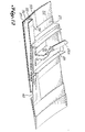
- FIG. 1 shows the core cowl 30 and its associated structures in a typical installation in association with a jet engine mounted on an aircraft wing 2.
- FIG. 1 shows the core cowl 30 and its associated structures in a typical installation in association with a jet engine mounted on an aircraft wing 2.
- FIG. 1 shows the core cowl 30 and its associated structures in a typical installation in association with a jet engine mounted on an aircraft wing 2.
- a number of conventional features are illustrated in Fig. 1. These features include the wing 2 of the aircraft, the frame member 4 extending from the wing 2 and on which the engine is mounted, the forward strut fairing 6, the fan 8, the exhaust plug 10, the nozzle exhaust sleeve 12, and the nose cap 14.
- Such features are all standard in jet engines and may be varied considerably without affecting the functioning of the structures that are a part of the apparatus of the present invention.
- the load carrying core cowl 30 of the present invention is an essentially cylindrical structure that surrounds the core of the engine in the conventional manner.
- the outer surface of the sidewall 32 of the cowl 30 is positioned, also in a conventional manner, to be exposed to a cooling airstream. This airstream is normally provided by the flow of ambient air.
- the cowl 30 is made of a material that can withstand heat but that loses structural strength as its temperature rises above a predetermined levul.
- the cowl 30 includes an essentially cylindrical sidewall 32 and stiffening means for stiffening the cowl 30. The stiffening means increases the structural strength of the cowl 30.
- the stiffening means includes a plurality of hollow tubular beams 34 on the inner surface of the sidewall 32 of the cowl 30. These beams preferably extend axially along the inner surface of the sidewall 32 of the cowl 30 and are distributed circumferentially about this inner surface. In the preferred embodiment, these axial beams 34 are spaced circumferentially about the inner surface of the sidewall 32, and the stiffening means also includes a plurality of axially spaced ci rcumferenti al beams 38 that extend circumferentially around the inner surface of the sidewall 32 of the cowl 30.
- the beams could also be arranged, without departing from the spirit and scope of the invention, in any of a variety of different patterns that provide the required stiffening. By way of nonlimitative example only, they could be arranged in a helical pattern.
- each of the circumferential and the axial reinforcing beams 34, 38 are tubular and have a wall portion 36 that is spaced from the inner surface of the sidewall 32 of the cowl 30.
- the wall portion 36 of each of the beams 34, 38 is also essentially parallel to the inner surface of the sidewall 32.
- each of the axial and circumferential beams 34 ,38 is a hollow box beam.
- Each such box beam is rectangular in cross section with two side webs 35 extending radially inwardly from the sidewall 32 and a radially inward wall portion 36 that connects the radially inner ends of the two side webs 35.
- This radially inward wall 36 forms the wall portion that is essentially parallel to and spaced from the inner surface of the sidewall 32 of the cowl 30.
- the sidewall 32 of the cowl 30, the two side webs 35, and the radially inward wall 36 that connects the webs 35 together define an essentially rectangular passageway 37, 39 through each of the beams 34, 38.
- the axial bourns 34 and the circumferential beams 38 are interconnected when they cross each other in a manner in which the rectangular passageways 37, 39 through the beams are interconnected. This allows the passage of cooling air between the axial and the circumferential beams 34, 38.
- the beams 34, 38 and the passageways 37, 39 in the preferred embodiment shown in the drawings are rectangular in cross section, beams and/or passageways with differently shaped cross sections could also be provided.
- the passageway cross sections might be circular, elliptical, or triangular.
- the cowl 30 is preferably made of a lightweight composite material. Most currently known composite materials are not suitable for use in constructing the cowl 30 because they lose their structural strength when their temperatures rise to relatively low levels. However, certain newly available composite materials maintain their structural strength at higher temperatures. One such material is Graphite/PMR-15 Polyimide, developed by the National Aeronautics and Space Administration. This composite maintains its structural strength at temperatures in the range of 500 to 550 degrees F. and has an estimated useful life of 10,000 hours at 500 degrees F. Other lightweight composite materials that similarly maintain their structural strength at such temperatures could also be used to construct the cowl 30.
- the cowl 30 is made of laminate panels of such a composite material, and the axial and the circumferential beams 34, 38 are formed integrally with the sidewall 32 of the cowl 30.
- This construction has the advantages of maximizing both structural strength and lightness and of being relatively inexpensive to manufacture.
- the flow of ambient air along the outer surface of the sidewall 32 of the cowl 30 is sufficient to maintain the temperature of the sidewall 32 at or below the 500 degree range.
- portions of the axial and circumferential beams 34, 38 to heat to a temperature higher than the 500 degree range. This tendency is due to the greater proximity of the beams 34, 38 to the high engine temperatures and to the relative remoteness of the beams 34, 38 from the flow of ambient air that moves along the outer surface of the sidewall 32 of the cowl 30.
- Composite materials such as those used to construct the cowl 30 do not have sufficient thermal conductivity to allow the cooling of the outer surface of the sidewall 32 to provide sufficient cooling for the inner portions of the beams 34, 3f3.
- the need for cooling is one of the reasons thit the reinforcing beams, the axial and circumferential beams 34, 38, are provided in tubular form.
- the tubular form of the beams 34, 38 makes it possible to direct cooling air through the beams 34, 38 and through the interconnecting passageways 37, 39 formed by the beams 34, 38.
- Fig. 7 shows a cross section of one of the beams 34, 38.
- Fig. 6 shows a cross section of a well known wide flange beam configuration 99 that is used for structural reinforcement of surfaces. A composite beam with such a configuration could not be properly cooled and, therefore, would fail when its inner portion was subjected to high engine temperatures.
- each beam 34, 38 formed by two side webs 35, a radial inward wall 36, and a portion of the sidewall 32 of the cowl 30 properly functions as a structural beam to reinforce the strength of the cowl 30.
- each radially inward wall 36 and the portion ot the sidewall 30 having essentially equal strength, each is able to carry the compression or tension forces created in it by the tendency of the cowl 30 to bend.
- the neutral plane (the plane between the compressed member and the tensioned member at which both compression and tension are zero) is maintained in its desired position substantially halfway between the radially inward wall 36 and the sidewall 30, and the beam 34, 38 functions efficiently as a structural reinforcement.
- the provision of the correct amount of flow of cooling air by metering the flow is important to the functioning of the cowl 30 because it maintains the compressed portion and the tensioned portion of the beam 34, 38 at essentially the same temperature level so that the strength of each of these portions is substantially equal.
- the flow of cooling air through the beams 34, 38 may be provided in several ways.
- the flow is provided by using forced aspiration to channel ambient air through the passageways 37, 39 formed by the beams 34, 38.
- inlet means are provided at the forward end of the cowl 30, and outlet means are provided at the rear end of the cowl 30.
- a suitable inlet 40 is located at the forward end of each axial beam 34, and a suitable outlet 42 is located at the rear end of each axial beam 34.
- These inlets 40 and outlets 42 are positioned in a known manner to take advantage of the relative velocity between the air inlet 40 and the air stream flowing past the cowl 30 and to minimize drag.
- the inlet 40 is formed flush with the outer surface of the cowl 30 and angled slightly forward.
- the outlet 42 is formed flush with the outer surface of the cowl 30 and is angled slightly to the rear of the cowl 30.
- the flow of cooling air is aspirated through the passageways 37, 39.
- the flow of cooling air could be provided in other ways.
- One such way is to induce the flow of air by producing a suction effect through the passageways 37, 39 in the beams 34, 38 by injecting a flow of gases past an outlet opening in the passageways.
- Flow of cooling air may also be provided by supplying bleed air from the compressor in the engine.
- the metering of the flow of cooling air is automatically provided by the structure of the beams 34, 38 and the inlet and outlet openings 40, 42.
- the sizes of the beams 34, 38 and the passageways 37, 39 extending through them are carefully selected to permit the desired amount of flow through them.
- the sizes and positions of the inlets 40 and outlets 42 are selected to create forced aspiration of the proper magnitude to maintain the desired amount of flow of cooling air.
- the jet engine shown in Fig. 1 is connected to the frame member 4 carried by the wing 2.
- the engine fan casing 18A is connected to the frame 4 at a forward location 15, and an aft portion of the engine core casing 18B is connected to the frame 4 at an aft location 16.
- the fan casing 18A is connected to a forward portion of the core casing 18B through a series of radial struts 19.
- the engine core casing 18B acts as a beam and carries the bending loads caused by the thrust and by the air loads acting on the aircraft.
- the engine casing carries all of the bending loads. With the development of larger aircraft with larger engines of lighter weight construction, the bending loads on the engine casing have increased to a magnitude sufficient to cause serious performance deterioration of the engine.
- connecting means are provided for connecting the core cowl to the engine mounting frame and for structurally integrating the engine casing with the core cowl.
- the core cowl acts as a beam which is subject to bending during engine operation.
- the core cowl shares bending loads with the engine. This division of bending loads between concentric beams allows the engine to carry its share of the loads without experiencing undesirable performance deterioration.
- the preferred embodiment of the structural integration of the engine core casing 18B with the core cowl 30 has various aspects. (See Figs. 3 and 12) One such aspect is that the forward attachments to the engine core casing 18B, via the cowl support shroud 20, have been increased over the conventional attachments to be load-bearing.
- a V-groove is provided on the aft end of the shroud 20, and a complementary V-tongue 24 is provided at the forward edges of the cowl doors 31 that form the essentially cylindrical cowl 30.
- a forward cowl door tensioner 26 on the ladder cowl support structure 22 of the engine core casing 18B provides hoop tension to make the connection load-bearing.
- An automatically operated hoop tensioning device is provided.
- This device is only in operation when the engine is running so that it will not interfere with maintenance accessibility.
- a support ring frame 27 At the rear of the cowl doors 31, there is located a support ring frame 27.
- This support ring frame 27 receives a load transfer ring 29 which is carried by the engine core casing 18B and which transmits reactions evenly to the rear of the casing 1813.
- An aft cowl door tensioner 28 is provided on the ladder support structure 22 in association with this ring 29.
- the load transfer ring 29 preferably includes swivel links 29A (See Fig. 12) which allow for thermal expansion of the engine under all loading conditions.
- Hinges 50 such as the one shown in Fig. 9, are provided along the axial edges of the cowl doors 31 to allow pivoting of the doors 31 when they are opened.
- Latches 52 are provided to secure the two cowl doors 31 together, with each of the cowl doors 31 forming one-half of the esssentially cylindrical cowl 30.
- the load-bearing connections between the cowl 30 and the engine casing at the forward end of the cowl (through the intermediate shroud 20)and the aft end of the cowl 30 (through the load transfer ring 29) structurally integrate the cowl 30 with the engine casing. This results in the desired load sharing between the engine casing and the cowl 30.
- Each of the cowl 30 and the engine casing acts as a beam that carries a share of the bending loads.
- Static load tests have been conducted to test the load sharing concept that is an aspect of the present invention. Simulated thrust loads and cowl bending moments were applied to apparatus constructed according to the invention. The results of the tests were overwhelmingly favorable. Sixty percent load sharing was achieved in the turbine section, and over forty percent load sharing in the fan section. The stiffening effect in the fan case will be extremely helpful in solving the problem of instability in the fan. The test results indicated that over 75% of the deterioration in the thrust-specific fuel consumption of the aircraft due to backbone bending of the engine can be prevented by use of a load carrying core cowl. In addition, the engine casing offset can be reduced, producing a gain in the initial thrust-specific fuel consumption.
- the apparatus and method of the present invention greatly reduce engine performance deterioration, and therefore greatly reduce maintenance costs and loss of fuel efficiency.
- the benefits of the reduction in performance deterioration can be obtained with little or no weight penalty being incurred.
Landscapes
- Engineering & Computer Science (AREA)
- Aviation & Aerospace Engineering (AREA)
- Chemical & Material Sciences (AREA)
- Combustion & Propulsion (AREA)
- Mechanical Engineering (AREA)
- General Engineering & Computer Science (AREA)
- Structures Of Non-Positive Displacement Pumps (AREA)
- Heat Treatment Of Articles (AREA)
Priority Applications (2)
| Application Number | Priority Date | Filing Date | Title |
|---|---|---|---|
| DE8383112786T DE3374546D1 (en) | 1983-12-19 | 1983-12-19 | Apparatus and method for minimizing engine backbone bending |
| EP83112786A EP0145809B1 (fr) | 1983-12-19 | 1983-12-19 | Système et méthode pour minimiser la flexion axiale dans un moteur |
Applications Claiming Priority (1)
| Application Number | Priority Date | Filing Date | Title |
|---|---|---|---|
| EP83112786A EP0145809B1 (fr) | 1983-12-19 | 1983-12-19 | Système et méthode pour minimiser la flexion axiale dans un moteur |
Publications (2)
| Publication Number | Publication Date |
|---|---|
| EP0145809A1 true EP0145809A1 (fr) | 1985-06-26 |
| EP0145809B1 EP0145809B1 (fr) | 1987-11-19 |
Family
ID=8190892
Family Applications (1)
| Application Number | Title | Priority Date | Filing Date |
|---|---|---|---|
| EP83112786A Expired EP0145809B1 (fr) | 1983-12-19 | 1983-12-19 | Système et méthode pour minimiser la flexion axiale dans un moteur |
Country Status (2)
| Country | Link |
|---|---|
| EP (1) | EP0145809B1 (fr) |
| DE (1) | DE3374546D1 (fr) |
Cited By (7)
| Publication number | Priority date | Publication date | Assignee | Title |
|---|---|---|---|---|
| GB2202588B (en) * | 1987-03-02 | 1991-09-25 | Gen Electric | Turbofan engine |
| FR2909974A1 (fr) * | 2006-12-13 | 2008-06-20 | Aircelle Sa | Nacelle pour turboreacteur double flux |
| JP2010536658A (ja) * | 2007-08-27 | 2010-12-02 | エアバス・オペレーションズ | アタッチメントパイロン及びナセルの吸気口に搭載されたファンカウル支持クレードル |
| US8739552B2 (en) | 2006-06-30 | 2014-06-03 | Aircelle | Structural nacelle |
| FR3001199A1 (fr) * | 2013-01-23 | 2014-07-25 | Snecma | Capot de moteur incorporant un circuit de ventilation d'equipement |
| CN108146641A (zh) * | 2016-12-05 | 2018-06-12 | 波音公司 | 具有定制厚度的核心的复合风扇整流罩 |
| CN114379795A (zh) * | 2020-10-16 | 2022-04-22 | 通用电气公司 | 推进发动机和整流罩 |
Families Citing this family (2)
| Publication number | Priority date | Publication date | Assignee | Title |
|---|---|---|---|---|
| RU2210523C1 (ru) * | 2001-12-14 | 2003-08-20 | Открытое акционерное общество "Авиационный комплекс им. С.В. Ильюшина" | Гондола силовой установки летательного аппарата |
| FR3147252A1 (fr) * | 2023-03-29 | 2024-10-04 | Airbus Operations | Ensemble propulsif d’aéronef comportant une nacelle avec un châssis en t |
Citations (4)
| Publication number | Priority date | Publication date | Assignee | Title |
|---|---|---|---|---|
| US3013641A (en) * | 1957-04-29 | 1961-12-19 | Thompson Ramo Wooldridge Inc | Structural element |
| US3981449A (en) * | 1968-01-29 | 1976-09-21 | The United States Of America As Represented By The Secretary Of The Navy | Exhaust cooling system |
| GB2046193A (en) * | 1979-04-10 | 1980-11-12 | Boeing Co | Aircraft Engine Installation |
| GB2072752A (en) * | 1980-04-02 | 1981-10-07 | United Technologies Corp | Case deflection control in aircraft gas turbine engines |
-
1983
- 1983-12-19 EP EP83112786A patent/EP0145809B1/fr not_active Expired
- 1983-12-19 DE DE8383112786T patent/DE3374546D1/de not_active Expired
Patent Citations (4)
| Publication number | Priority date | Publication date | Assignee | Title |
|---|---|---|---|---|
| US3013641A (en) * | 1957-04-29 | 1961-12-19 | Thompson Ramo Wooldridge Inc | Structural element |
| US3981449A (en) * | 1968-01-29 | 1976-09-21 | The United States Of America As Represented By The Secretary Of The Navy | Exhaust cooling system |
| GB2046193A (en) * | 1979-04-10 | 1980-11-12 | Boeing Co | Aircraft Engine Installation |
| GB2072752A (en) * | 1980-04-02 | 1981-10-07 | United Technologies Corp | Case deflection control in aircraft gas turbine engines |
Cited By (14)
| Publication number | Priority date | Publication date | Assignee | Title |
|---|---|---|---|---|
| GB2202588B (en) * | 1987-03-02 | 1991-09-25 | Gen Electric | Turbofan engine |
| US8739552B2 (en) | 2006-06-30 | 2014-06-03 | Aircelle | Structural nacelle |
| FR2909974A1 (fr) * | 2006-12-13 | 2008-06-20 | Aircelle Sa | Nacelle pour turboreacteur double flux |
| WO2008093003A1 (fr) * | 2006-12-13 | 2008-08-07 | Aircelle | Nacelle pour turboréacteur double flux |
| CN101541635B (zh) * | 2006-12-13 | 2012-05-02 | 埃尔塞乐公司 | 涡轮风扇发动机的发动机舱 |
| US8668441B2 (en) | 2006-12-13 | 2014-03-11 | Aircelle | Deformable structural framework for a turbofan nacelle |
| JP2010536658A (ja) * | 2007-08-27 | 2010-12-02 | エアバス・オペレーションズ | アタッチメントパイロン及びナセルの吸気口に搭載されたファンカウル支持クレードル |
| FR3001199A1 (fr) * | 2013-01-23 | 2014-07-25 | Snecma | Capot de moteur incorporant un circuit de ventilation d'equipement |
| GB2513215A (en) * | 2013-01-23 | 2014-10-22 | Snecma | Engine cowl incorporating an equipment ventilation circuit |
| US10077113B2 (en) | 2013-01-23 | 2018-09-18 | Safran Aircraft Engines | Engine cowl incorporating an equipment ventilation circuit |
| GB2513215B (en) * | 2013-01-23 | 2019-07-10 | Snecma | Engine cowl incorporating an equipment ventilation circuit |
| CN108146641A (zh) * | 2016-12-05 | 2018-06-12 | 波音公司 | 具有定制厚度的核心的复合风扇整流罩 |
| CN108146641B (zh) * | 2016-12-05 | 2023-08-04 | 波音公司 | 具有定制厚度的核心的复合风扇整流罩 |
| CN114379795A (zh) * | 2020-10-16 | 2022-04-22 | 通用电气公司 | 推进发动机和整流罩 |
Also Published As
| Publication number | Publication date |
|---|---|
| DE3374546D1 (en) | 1987-12-23 |
| EP0145809B1 (fr) | 1987-11-19 |
Similar Documents
| Publication | Publication Date | Title |
|---|---|---|
| US4471609A (en) | Apparatus and method for minimizing engine backbone bending | |
| EP1857639B1 (fr) | Chassis de soufflante | |
| US8523516B2 (en) | Bypass turbojet engine nacelle | |
| EP2895392B1 (fr) | Structure sandwich métallique à faible rayon de courbure | |
| US6364603B1 (en) | Fan case for turbofan engine having a fan decoupler | |
| US4240250A (en) | Noise reducing air inlet for gas turbine engines | |
| US9828105B2 (en) | Nacelle assembly having integrated afterbody mount case | |
| US4826403A (en) | Turbine | |
| EP0244515A2 (fr) | Moteur d'avion à soufflante avec carénage tournant | |
| US4712750A (en) | Temperature control device for jet engine nacelle associated structure | |
| EP3009649B1 (fr) | Conduite d'écoulement externe intégrée et système de cadre avant destiné à être utilisé dans un moteur à turboréacteur et son procédé de fabrication | |
| EP0145809A1 (fr) | Système et méthode pour minimiser la flexion axiale dans un moteur | |
| US11753968B2 (en) | Nacelle cowling structure for a turbomachine | |
| CN113277094B (zh) | 飞行器及推进发动机安装系统 | |
| EP3628589B1 (fr) | Plénums structuraux fixes de commande de flux laminaire actif | |
| US12392305B2 (en) | Aircraft propulsion unit | |
| US10767493B2 (en) | Turbine vane assembly with ceramic matrix composite vanes | |
| EP4474281A1 (fr) | Structure d'entrée de nacelle à noyau en mousse | |
| US20220119123A1 (en) | Propulsion engine and cowl | |
| US20250101915A1 (en) | Air intake for an aircraft propulsion system engine assembly | |
| Wilde et al. | The Rolls‐Royce Three Shaft Turbofan Engine: A detailed examination of the new family of advanced technology engines under development by Rolls‐Royce Ltd. | |
| German et al. | Design and evaluation of an integrated Quiet, Clean General Aviation Turbofan (QCGAT) engine and aircraft propulsion system | |
| US12071855B2 (en) | Conduit bushing with cellular material | |
| Jackson | An introduction to the JT9D engine | |
| Gertsma et al. | Propulsion system for research VTOL transports |
Legal Events
| Date | Code | Title | Description |
|---|---|---|---|
| PUAI | Public reference made under article 153(3) epc to a published international application that has entered the european phase |
Free format text: ORIGINAL CODE: 0009012 |
|
| AK | Designated contracting states |
Designated state(s): DE FR GB IT NL |
|
| 17P | Request for examination filed |
Effective date: 19851224 |
|
| 17Q | First examination report despatched |
Effective date: 19860915 |
|
| ITF | It: translation for a ep patent filed | ||
| GRAA | (expected) grant |
Free format text: ORIGINAL CODE: 0009210 |
|
| AK | Designated contracting states |
Kind code of ref document: B1 Designated state(s): DE FR GB IT NL |
|
| REF | Corresponds to: |
Ref document number: 3374546 Country of ref document: DE Date of ref document: 19871223 |
|
| ET | Fr: translation filed | ||
| PLBE | No opposition filed within time limit |
Free format text: ORIGINAL CODE: 0009261 |
|
| STAA | Information on the status of an ep patent application or granted ep patent |
Free format text: STATUS: NO OPPOSITION FILED WITHIN TIME LIMIT |
|
| 26N | No opposition filed | ||
| PGFP | Annual fee paid to national office [announced via postgrant information from national office to epo] |
Ref country code: GB Payment date: 19901203 Year of fee payment: 8 |
|
| PGFP | Annual fee paid to national office [announced via postgrant information from national office to epo] |
Ref country code: FR Payment date: 19901221 Year of fee payment: 8 |
|
| ITTA | It: last paid annual fee | ||
| PGFP | Annual fee paid to national office [announced via postgrant information from national office to epo] |
Ref country code: NL Payment date: 19901231 Year of fee payment: 8 |
|
| PGFP | Annual fee paid to national office [announced via postgrant information from national office to epo] |
Ref country code: DE Payment date: 19910131 Year of fee payment: 8 |
|
| PG25 | Lapsed in a contracting state [announced via postgrant information from national office to epo] |
Ref country code: GB Effective date: 19911219 |
|
| PG25 | Lapsed in a contracting state [announced via postgrant information from national office to epo] |
Ref country code: NL Effective date: 19920701 |
|
| NLV4 | Nl: lapsed or anulled due to non-payment of the annual fee | ||
| GBPC | Gb: european patent ceased through non-payment of renewal fee | ||
| PG25 | Lapsed in a contracting state [announced via postgrant information from national office to epo] |
Ref country code: FR Effective date: 19920831 |
|
| PG25 | Lapsed in a contracting state [announced via postgrant information from national office to epo] |
Ref country code: DE Effective date: 19920901 |
|
| REG | Reference to a national code |
Ref country code: FR Ref legal event code: ST |