EP0145559A2 - Electrical device containing at least one thermal cell, and its use as an energy generator that can be modulated - Google Patents
Electrical device containing at least one thermal cell, and its use as an energy generator that can be modulated Download PDFInfo
- Publication number
- EP0145559A2 EP0145559A2 EP84402315A EP84402315A EP0145559A2 EP 0145559 A2 EP0145559 A2 EP 0145559A2 EP 84402315 A EP84402315 A EP 84402315A EP 84402315 A EP84402315 A EP 84402315A EP 0145559 A2 EP0145559 A2 EP 0145559A2
- Authority
- EP
- European Patent Office
- Prior art keywords
- thermal
- battery
- electrical device
- cell
- switch
- Prior art date
- Legal status (The legal status is an assumption and is not a legal conclusion. Google has not performed a legal analysis and makes no representation as to the accuracy of the status listed.)
- Granted
Links
- 239000012190 activator Substances 0.000 claims abstract description 11
- 239000003792 electrolyte Substances 0.000 claims abstract description 6
- 239000011810 insulating material Substances 0.000 claims description 5
- -1 polyethylene Polymers 0.000 claims description 5
- MWPLVEDNUUSJAV-UHFFFAOYSA-N anthracene Chemical compound C1=CC=CC2=CC3=CC=CC=C3C=C21 MWPLVEDNUUSJAV-UHFFFAOYSA-N 0.000 claims description 4
- 239000004417 polycarbonate Substances 0.000 claims description 3
- 229920000515 polycarbonate Polymers 0.000 claims description 3
- 239000004698 Polyethylene Substances 0.000 claims description 2
- 230000004927 fusion Effects 0.000 claims description 2
- 229920000573 polyethylene Polymers 0.000 claims description 2
- 229920002635 polyurethane Polymers 0.000 claims description 2
- 239000004814 polyurethane Substances 0.000 claims description 2
- 230000004913 activation Effects 0.000 description 9
- 238000012423 maintenance Methods 0.000 description 3
- 238000007789 sealing Methods 0.000 description 2
- 239000007787 solid Substances 0.000 description 2
- 230000006978 adaptation Effects 0.000 description 1
- 239000004020 conductor Substances 0.000 description 1
- 239000012777 electrically insulating material Substances 0.000 description 1
- 230000007613 environmental effect Effects 0.000 description 1
- 238000010438 heat treatment Methods 0.000 description 1
- 229910052500 inorganic mineral Inorganic materials 0.000 description 1
- 230000007257 malfunction Effects 0.000 description 1
- 238000004519 manufacturing process Methods 0.000 description 1
- 239000000463 material Substances 0.000 description 1
- 230000008018 melting Effects 0.000 description 1
- 238000002844 melting Methods 0.000 description 1
- 239000011707 mineral Substances 0.000 description 1
- 238000012544 monitoring process Methods 0.000 description 1
- 230000007935 neutral effect Effects 0.000 description 1
- 230000003287 optical effect Effects 0.000 description 1
- 238000011084 recovery Methods 0.000 description 1
- 150000003839 salts Chemical class 0.000 description 1
- 239000000126 substance Substances 0.000 description 1
Images
Classifications
-
- H—ELECTRICITY
- H01—ELECTRIC ELEMENTS
- H01M—PROCESSES OR MEANS, e.g. BATTERIES, FOR THE DIRECT CONVERSION OF CHEMICAL ENERGY INTO ELECTRICAL ENERGY
- H01M6/00—Primary cells; Manufacture thereof
- H01M6/50—Methods or arrangements for servicing or maintenance, e.g. for maintaining operating temperature
- H01M6/5011—Methods or arrangements for servicing or maintenance, e.g. for maintaining operating temperature for several cells simultaneously or successively
-
- H—ELECTRICITY
- H01—ELECTRIC ELEMENTS
- H01M—PROCESSES OR MEANS, e.g. BATTERIES, FOR THE DIRECT CONVERSION OF CHEMICAL ENERGY INTO ELECTRICAL ENERGY
- H01M50/00—Constructional details or processes of manufacture of the non-active parts of electrochemical cells other than fuel cells, e.g. hybrid cells
- H01M50/50—Current conducting connections for cells or batteries
- H01M50/572—Means for preventing undesired use or discharge
- H01M50/574—Devices or arrangements for the interruption of current
- H01M50/581—Devices or arrangements for the interruption of current in response to temperature
-
- H—ELECTRICITY
- H01—ELECTRIC ELEMENTS
- H01M—PROCESSES OR MEANS, e.g. BATTERIES, FOR THE DIRECT CONVERSION OF CHEMICAL ENERGY INTO ELECTRICAL ENERGY
- H01M6/00—Primary cells; Manufacture thereof
- H01M6/30—Deferred-action cells
- H01M6/36—Deferred-action cells containing electrolyte and made operational by physical means, e.g. thermal cells
-
- H—ELECTRICITY
- H01—ELECTRIC ELEMENTS
- H01M—PROCESSES OR MEANS, e.g. BATTERIES, FOR THE DIRECT CONVERSION OF CHEMICAL ENERGY INTO ELECTRICAL ENERGY
- H01M6/00—Primary cells; Manufacture thereof
- H01M6/50—Methods or arrangements for servicing or maintenance, e.g. for maintaining operating temperature
-
- H—ELECTRICITY
- H01—ELECTRIC ELEMENTS
- H01M—PROCESSES OR MEANS, e.g. BATTERIES, FOR THE DIRECT CONVERSION OF CHEMICAL ENERGY INTO ELECTRICAL ENERGY
- H01M2200/00—Safety devices for primary or secondary batteries
- H01M2200/10—Temperature sensitive devices
Definitions
- the present invention relates to an electrical device comprising at least one thermal battery and its application to a modular electrical energy generator.
- thermal batteries disposable and relatively short-lived, in which the electrolyte is normally inert and must be activated via an activator.
- this electrolyte is constituted by a fusible mineral salt which is in the solid state and electrically inert at room temperature, but becomes electrically active as soon as it has been melted by the activator, which is then an initiated pyrotechnic igniter. - only.
- thermal batteries very particularly suitable for supplying electronic devices for monitoring, surveillance, alarm, emergency, etc., all the more so since, even when connected to their circuit of use, they do not flow spontaneously, but on the contrary must be activated to do so.
- the object of the present invention is to remedy this drawback and in particular to allow the production of an electrical energy generator, composed of thermal cells and capable of delivering modular electrical energy over time. Thanks to the invention, it is then possible to overcome the faults of dry cells and accumulators, mainly concerning their delicate maintenance, their short service life, their random sealing and their little resistance to a harsh environment.
- thermal cells are the seat of a release of heat subjecting their elements, in particular to their casing, to a continuous increase in temperature such that a temperature of said elements corresponds to a determined instant of the operation of such a cell, that is to say an internal state thereof.
- a temperature of said elements corresponds to a determined instant of the operation of such a cell, that is to say an internal state thereof.
- the temperature of the case of such a thermal cell placed at ambient temperature increases linearly from this ambient temperature, at the instant of activation, to a maximum temperature (generally between 150 and 300 ° C.) reached at l expiration of operation.
- the present invention provides an electrical device comprising at least one thermal battery in which the electrolyte, normally inert, must be activated by means of an activator and whose temporary operation is accompanied by a release of heat subjecting elements of said cell to an increase in temperature such that at a determined temperature of said elements corresponds to a determined instant of operation of said cell, characterized in that it comprises at least one thermal switch which is arranged in connection thermal with an element, belonging to or linked to said cell, and which is designed to operate at a predetermined temperature, included in the range of temperatures taken by said element during the operation of said cell.
- said thermal switch can control an electrical circuit as soon as the operation of said battery reaches a predetermined state.
- said thermal switch is mounted on the case of said cell and is in thermal connection with the latter. It is then advantageous for said housing to be at least partly electrically conductive and to be part of the electrical circuit controlled by said switch.
- the switch can then include a conductive latch, for example of the spring type, pressed in the direction of the case of said cell, but separated from the latter by an insulating material which can either be eliminated by fusion, or to become conductive, in response to the increase in temperature of the portion of the housing in contact with which it is.
- a conductive latch for example of the spring type, pressed in the direction of the case of said cell, but separated from the latter by an insulating material which can either be eliminated by fusion, or to become conductive, in response to the increase in temperature of the portion of the housing in contact with which it is.
- the softening or melting or conduction temperature not only corresponds to the temperature of the battery to which it is desired to activate the electric circuit controlled, but still is higher than the maximum temperature of the environment in which the battery is located, before its activation.
- thermal switch of the element of the battery to which it is connected, of the connection between said element and said switch, of the location of the switch on said element, etc. can be made for that the actuation of said switch is made upon activation of the battery, during operation thereof, or even after this operation proper.
- thermal switches can be associated with said battery for the purpose of controlling several electrical circuits and / or of delivering signals at different times during the operation of said battery.
- the thermal switch or switches controlled by the heating of said battery may themselves be arranged in the control circuit of the activator of another thermal battery.
- these two thermal cells can operate simultaneously, with partial or total operating recovery, or alternatively.
- a plurality of thermal batteries of the type described above is provided, each of which is associated with at least one thermal switch in order to be able to control at least one of the said Battery.
- the batteries of said plurality can be mounted in parallel with each other on the same user device without the intermediary of 'light switch.
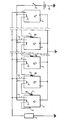
- a generator is thus obtained consisting of a cascade of thermal cells which are arranged in parallel on a device to be supplied and the activator of each of which is controlled by the thermal switch associated with the preceding thermal cell in the cascade, except for the first one which is ordered directly and voluntarily by an operator.
- the generator according to the invention comprises a plurality of thermal cells P 1 , P 2 , .. P i , .. P n of the type described above.
- Each of these batteries comprises a box 1, made of a conductive material and connected to the cathode, an anode 2 and an igniter (or activator) 3.
- the igniter 3 of the battery P 1 is supplied via the contact 6 and the housing 1 of the said battery. Consequently, the battery P 1 is activated and begins to deliver its energy to the user device 4.
- the rest of the operation of the device in the single figure may be different.
- the material 8 and the location on the housings 1 of the thermal switches 7,8 are each chosen so that the switch 7,8 of a P i-1 battery operates just before the moment when this P i-1 battery, activated, will finish delivering its energy to the device 4, so that the igniter 3 of the next battery P i is actuated at this time through the switch 7,8 and the housing 1 of the previous battery P i-1 .
- the thermal switches 7,8 and their arrangement are provided so that the n batteries Pi are activated simultaneously, that is to say so that all the switches 7,8 immediately reach their operating temperature and transmit the activation order from the battery P 2 to the battery P n .
- the user device 4 may require operating periods between which durations varying from seconds to ten years may elapse, each operating period being delimited by closing, then the opening of the switch 5. Within each of said operating periods, it is possible, in the manner described above, to activate one or more Pi batteries, successively or simultaneously.
- the energy required to control the igniters 3 is very low, so that the battery 4 which supplies it (or any other device, such as a piezoelectric system) can be very far from all of the batteries P i .
- one or more batteries P i can be provided with several thermal switches 7,8 to control other control and use chains.
Landscapes
- Chemical & Material Sciences (AREA)
- Chemical Kinetics & Catalysis (AREA)
- Electrochemistry (AREA)
- General Chemical & Material Sciences (AREA)
- Engineering & Computer Science (AREA)
- Manufacturing & Machinery (AREA)
- Primary Cells (AREA)
- Control Of Electrical Variables (AREA)
- Charge And Discharge Circuits For Batteries Or The Like (AREA)
- Secondary Cells (AREA)
- Thermotherapy And Cooling Therapy Devices (AREA)
- Electromechanical Clocks (AREA)
- Electrochromic Elements, Electrophoresis, Or Variable Reflection Or Absorption Elements (AREA)
Abstract
Description
La présente invention concerne un dispositif électrique comportant au moins une pile thermique et son application à un générateur d'énergie électrique modulable.The present invention relates to an electrical device comprising at least one thermal battery and its application to a modular electrical energy generator.
On connaît déjà des piles thermiques, à usage unique et à fonctionnement de durée relativement courte, dans lesquelles l'électrolyte est normalement inerte et doit être activé par l'intermédiaire d'un activateur. Par exemple, cet électrolyte est constitué par un sel minéral fusible se présentant à l'état solide et électriquement inerte à la température ambiante, mais devenant électriquement actif dès qu'il a été fondu par l'activateur, qui est alors un inflammateur initié pyrotechni- quement.There are already known thermal batteries, disposable and relatively short-lived, in which the electrolyte is normally inert and must be activated via an activator. For example, this electrolyte is constituted by a fusible mineral salt which is in the solid state and electrically inert at room temperature, but becomes electrically active as soon as it has been melted by the activator, which is then an initiated pyrotechnic igniter. - only.
De telles piles thermiques présentent des particularités intéressantes, liées notamment au fait qu'avant leur activation l'électrolyte est électriquement neutre et solide :
- - leur durée de vie, en stockage avant activation, est au moins égale à vingt ans, si ce n'est plus ;
- - elles ne nécessitent aucune maintenance et leur étanchéité est parfaite ;
- - elles résistent à des conditions sévères d'environnement et peuvent être activées à tout moment, dans pratiquement n'importe quelles conditions. Elles admettent des conditions de température ambiante comprise entre -50.C et +70'C ;
- - elles présentent une très grande impédance avant et après fonctionnement.
- - their lifespan, in storage before activation, is at least twenty years, if not more;
- - They require no maintenance and their sealing is perfect;
- - they withstand severe environmental conditions and can be activated at any time, in almost any condition. They admit ambient temperature conditions between -50 . C and + 70'C;
- - they have a very high impedance before and after operation.
De telles propriétés avantageuses destineraient lesdites piles thermiques tout particulièrement à l'alimentation des dispositifs électroniques de veille, de surveillance, d'alarme, de secours, etc..., d'autant plus que, même connectées à leur circuit d'utilisation, elles ne débitent pas spontanément, mais au contraire doivent être activées pour ce faire.Such advantageous properties would make said thermal batteries very particularly suitable for supplying electronic devices for monitoring, surveillance, alarm, emergency, etc., all the more so since, even when connected to their circuit of use, they do not flow spontaneously, but on the contrary must be activated to do so.
Cependant, une telle application a été jusqu'à présent impossible à cause du fonctionnement seulement temporaire desdites piles après leur activation.However, such an application has hitherto been impossible because of the only temporary operation of said batteries after their activation.
La présente invention a pour objet de remédier à cet inconvénient et notamment de permettre la réalisation d'un générateur d'énergie électrique, composé de piles thermiques et susceptible de délivrer une énergie électrique modulable dans le temps. Grâce à l'invention, on peut alors s'affranchir des défauts des piles sèches et accumulateurs, concernant principalement leur maintenance délicate, leur faible durée de vie, leur étanchéité aléatoire et leur peu de résistance à un environnement sévère.The object of the present invention is to remedy this drawback and in particular to allow the production of an electrical energy generator, composed of thermal cells and capable of delivering modular electrical energy over time. Thanks to the invention, it is then possible to overcome the faults of dry cells and accumulators, mainly concerning their delicate maintenance, their short service life, their random sealing and their little resistance to a harsh environment.
L'idée de base de la présente invention repose sur la constatation que, pendant leur fonctionnement, ces piles thermiques sont le siège d'un dégagement de chaleur faisant subir à leurs éléments, notamment à leur boîtier, une augmentation continue de température telle qu'à une température desdits éléments correspond un instant déterminé du fonctionnement d'une telle pile, c'est-à-dire un état interne de celle-ci. Par exemple, la température du boitier d'une telle pile thermique placée à la température ambiante croit linéairement de cette température ambiante, à l'instant d'activation, à une température maximale (généralement comprise entre 150 et 300°C) atteinte à l'expiration du fonctionnement.The basic idea of the present invention is based on the observation that, during their operation, these thermal cells are the seat of a release of heat subjecting their elements, in particular to their casing, to a continuous increase in temperature such that a temperature of said elements corresponds to a determined instant of the operation of such a cell, that is to say an internal state thereof. For example, the temperature of the case of such a thermal cell placed at ambient temperature increases linearly from this ambient temperature, at the instant of activation, to a maximum temperature (generally between 150 and 300 ° C.) reached at l expiration of operation.
Pour exploiter cette propriété, la présente invention prévoit un dispositif électrique comportant au moins une pile thermique dans laquelle l'électrolyte, normalement inerte, doit être activé par l'intermédiaire d'un activateur et dont le fonctionnement temporaire s'accompagne d'un dégagement de chaleur faisant subir à des éléments de ladite pile une augmentation de température telle qu'à une température déterminée desdits éléments correspond un instant déterminé du fonctionnement de ladite pile, caractérisé en ce qu'il comporte au moins un interrupteur thermique qui est agencé en liaison thermique avec un élément, appartenant à ladite pile ou lié à celle-ci, et qui est prévu pour fonctionner à une température prédéterminée, comprise dans la plage des températures prises par ledit élément au cours du fonctionnement de ladite pile.To exploit this property, the present invention provides an electrical device comprising at least one thermal battery in which the electrolyte, normally inert, must be activated by means of an activator and whose temporary operation is accompanied by a release of heat subjecting elements of said cell to an increase in temperature such that at a determined temperature of said elements corresponds to a determined instant of operation of said cell, characterized in that it comprises at least one thermal switch which is arranged in connection thermal with an element, belonging to or linked to said cell, and which is designed to operate at a predetermined temperature, included in the range of temperatures taken by said element during the operation of said cell.
Ainsi, ledit interrupteur thermique peut commander un circuit électrique dès que le fonctionnement de ladite pile atteint un état prédéterminé.Thus, said thermal switch can control an electrical circuit as soon as the operation of said battery reaches a predetermined state.
De préférence, ledit interrupteur thermique est monté sur le boîtier de ladite pile et se trouve en liaison thermique avec celui-ci. Il est alors avantageux que ledit boîtier soit au moins en partie électriquement conducteur et fasse partie du circuit électrique commandé par ledit interrupteur.Preferably, said thermal switch is mounted on the case of said cell and is in thermal connection with the latter. It is then advantageous for said housing to be at least partly electrically conductive and to be part of the electrical circuit controlled by said switch.
Dans un mode de réalisation particulier, l'interrupteur peut alors comporter un linguet conducteur, par exemple du type ressort, pressé en direction du boîtier de ladite pile, mais séparé de celui-ci par une matière isolante susceptible, soit d'être éliminée par fusion, soit de devenir conductrice, en réponse à l'augmentation de température de la portion de boitier au contact de laquelle elle se trouve.In a particular embodiment, the switch can then include a conductive latch, for example of the spring type, pressed in the direction of the case of said cell, but separated from the latter by an insulating material which can either be eliminated by fusion, or to become conductive, in response to the increase in temperature of the portion of the housing in contact with which it is.
Bien entendu, pour éviter des défauts de fonctionnement au moment de l'activation de la pile, il est nécessaire de mettre en oeuvre des matières isolantes pour lesquelles la température de ramollissement ou de fusion ou de conduction, non seulement correspond à la température de la pile à laquelle on désire actionner le circuit électrique commandé, mais encore est supérieure à la température maximale de l'environnement dans lequel se trouve la pile, avant son activation.Of course, to avoid malfunctions at the time of activation of the cell, it is necessary to use insulating materials for which the softening or melting or conduction temperature not only corresponds to the temperature of the battery to which it is desired to activate the electric circuit controlled, but still is higher than the maximum temperature of the environment in which the battery is located, before its activation.
A titre d'exemple, on indique ci-après des substances isolantes pouvant être utilisées, en fonction de la température qui leur est appliquée :
- - jusqu'à 70°C : paraffines, stéarines
- - de 70°C à 100°C : polyéthylène
- - de 100°C à 160°C : polyuréthane
- - de 160°C à 210°C : anthracènes
- - de 210°C à 240°C : polycarbonates
- - de 240°C à 270°C : polyoxyphénylènes.
- - up to 70 ° C: paraffins, stearins
- - from 70 ° C to 100 ° C: polyethylene
- - from 100 ° C to 160 ° C: polyurethane
- - from 160 ° C to 210 ° C: anthracene
- - from 210 ° C to 240 ° C: polycarbonates
- - from 240 ° C to 270 ° C: polyoxyphenylenes.
Le choix de l'interrupteur thermique, de l'élément de la pile auquel il est relié, de la liaison entre ledit élément et ledit interrupteur, de l'emplacement de l'interrupteur sur ledit élément, etc... peut être fait pour que l'actionnement dudit interrupteur se fasse dès l'activation de la pile, pendant le fonctionnement de celle-ci, ou bien encore après ce fonctionnement proprement dit.The choice of the thermal switch, of the element of the battery to which it is connected, of the connection between said element and said switch, of the location of the switch on said element, etc. can be made for that the actuation of said switch is made upon activation of the battery, during operation thereof, or even after this operation proper.
Bien entendu, plusieurs interrupteurs thermiques peuvent être associés à ladite pile en vue de la commande de plusieurs circuits électriques et/ou de la délivrance de signaux à différents instants du fonctionnement de ladite pile.Of course, several thermal switches can be associated with said battery for the purpose of controlling several electrical circuits and / or of delivering signals at different times during the operation of said battery.
Le ou les interrupteurs thermiques commandés par l'échauffement de ladite pile peuvent eux-mêmes être disposés dans le circuit de commande de l'activateur d'une autre pile thermique. Ainsi, au choix, ces deux piles thermiques peuvent fonctionner simultanément, avec recouvrement partiel ou total de fonctionnement, ou bien successivement.The thermal switch or switches controlled by the heating of said battery may themselves be arranged in the control circuit of the activator of another thermal battery. Thus, as desired, these two thermal cells can operate simultaneously, with partial or total operating recovery, or alternatively.
De façon plus générale, pour obtenir un générateur continu selon l'invention, on prévoit une pluralité de piles thermiques du type décrit ci-dessus, dont chacune d'elles est associée à au moins un interrupteur thermique pour pouvoir commander au moins une autre desdites piles.More generally, to obtain a continuous generator according to the invention, a plurality of thermal batteries of the type described above is provided, each of which is associated with at least one thermal switch in order to be able to control at least one of the said Battery.
Du fait que, avant et après fonctionnement, de telles piles présentent une impédance très élevée et ne débitent aucun courant, les piles de ladite pluralité peuvent être montées en parallèle les unes sur les autres sur un même dispositif d'utilisation sans l'intermédiaire d'interrupteur. On obtient ainsi un générateur constitué d'une cascade de piles thermiques qui sont disposées en parallèle sur un appareil à alimenter et dont l'activateur de chacune d'elles est commandé par l'interrupteur thermique associé à la pile thermique précédente dans la cascade, sauf pour la première qui est commandée directement et volontairement par un opérateur.Because, before and after operation, such batteries have a very high impedance and do not draw any current, the batteries of said plurality can be mounted in parallel with each other on the same user device without the intermediary of 'light switch. A generator is thus obtained consisting of a cascade of thermal cells which are arranged in parallel on a device to be supplied and the activator of each of which is controlled by the thermal switch associated with the preceding thermal cell in the cascade, except for the first one which is ordered directly and voluntarily by an operator.
La figure unique du dessin annexé fera bien comprendre comment l'invention peut être réalisée.The single figure of the appended drawing will make it clear how the invention can be implemented.
Sur cette figure, on a représenté un exemple de réalisation d'un générateur à piles multiples selon l'invention.In this figure, there is shown an embodiment of a generator with multiple batteries according to the invention.
Le générateur selon l'invention, montré par la figure, comporte une pluralité de piles thermiques P1,P2,..Pi,..Pn du type décrit ci-dessus. Chacune de ces piles comporte un boitier 1, réalisé en une matière conductrice et relié à la cathode, une anode 2 et un inflammateur (ou activateur) 3.The generator according to the invention, shown in the figure, comprises a plurality of thermal cells P 1 , P 2 , .. P i , .. P n of the type described above. Each of these batteries comprises a
Dans l'exemple représenté :
- - tous les
boîtiers 1 sont reliés à la masse ; - - toutes les
anodes 2 sont reliées à la borne correspondante d'un appareil utilisateur 4, dont la borne opposée est reliée à la masse ; - - tous les
inflammateurs 3 sont reliés, d'un côté, à un dispositif de commande, constitué d'une pile 4 et d'un interrupteur 5, ou bien d'un système piezoélectrique ; - - le côté opposé de l'inflammateur 3 de la pile P1 est relié au
boitier 1 de ladite pile P1, par uncontact 6; et - - le côté opposé de l'inflammateur 3 des piles P2,P3'...Pi,...Pn est relié à un contact 7, ces contacts 7 étant respectivement pressés contre le
boitier 1 des piles P1,P2,···Pi-1,...Pn-1, avec interposition d'une couche de matière électriquement isolante 8.
- - all the
boxes 1 are connected to earth; - - All the
anodes 2 are connected to the corresponding terminal of a user device 4, the opposite terminal of which is connected to ground; - - All the
igniters 3 are connected, on one side, to a control device, consisting of a battery 4 and a switch 5, or else of a piezoelectric system; - - the opposite side of the
igniter 3 of the battery P 1 is connected to thecase 1 of the said battery P 1 , by acontact 6; and - the opposite side of the
igniter 3 of the batteries P 2 , P 3 ' ... P i , ... P n is connected to a contact 7, these contacts 7 being respectively pressed against thecasing 1 of the batteries P 1 , P 2 , ··· P i-1 , ... P n-1 , with the interposition of a layer of electrically insulatingmaterial 8.
Dès que l'on ferme l'interrupteur 5, l'inflammateur 3 de la pile P1 est alimenté par l'intermédiaire du contact 6 et du boîtier 1 de ladite pile. En conséquence, la pile P1 est activée et commence à délivrer son énergie à l'appareil utilisateur 4.As soon as the switch 5 is closed, the
En fonction de la nature des piles Pi, de la matière isolante 8 et de l'appareil utilisateur 4, la suite du fonctionnement du dispositif de la figure unique peut être différente.Depending on the nature of the batteries P i , the insulating
Dans le cas où l'appareil 4 doit être alimenté sous une puissance équivalente à celle de chacune des piles élémentaires Pi pendant un temps multiple du temps de fonctionnement d'une de celles-ci, la matière 8 et l'emplacement sur les boîtiers 1 des interrupteurs thermiques 7,8 sont à chaque fois choisis pour que l'interrupteur 7,8 d'une pile Pi-1 fonctionne juste avant le moment où cette pile Pi-1, activée, va finir de délivrer son énergie à l'appareil 4, de sorte que l'inflammateur 3 de la pile suivante Pi est actionné à ce moment à travers l'interrupteur 7,8 et le boîtier 1 de la pile précédente Pi-1.In the case where the apparatus 4 must be supplied with a power equivalent to that of each of the elementary batteries P i for a time multiple of the operating time of one of them, the
Si l'appareil 4 requiert une puissance n fois multiple de celle d'une pile élémentaire Pi, les interrupteurs thermiques 7,8 et leur agencement sont prévus pour que les n piles Pi soient activées simultanément, c'est-à-dire pour que tous les interrupteurs 7,8 atteignent immédiatement leur température de fonctionnement et transmettent l'ordre d'activation de la pile P2 vers le pile Pn.If the apparatus 4 requires a power n times multiple of that of an elementary battery Pi, the
Dans un autre type de fonctionnement, l'appareil utilisateur 4 peut requérir des périodes de fonctionnement entre lesquelles peut s'écouler des durées variant de la seconde à la dizaine d'année, chaque période de fonctionnement étant délimitée par la fermeture, puis l'ouverture de l'interrupteur 5. A l'intérieur de chacune desdites périodes de fonctionnement, on peut, de la façon décrite ci-dessus, mettre en action une ou plusieurs piles Pi, successivement ou simultanément.In another type of operation, the user device 4 may require operating periods between which durations varying from seconds to ten years may elapse, each operating period being delimited by closing, then the opening of the switch 5. Within each of said operating periods, it is possible, in the manner described above, to activate one or more Pi batteries, successively or simultaneously.
On comprendra aisément que d'autres modes de fonctionnement que ceux décrits ci-dessus peuvent être obtenus par adaptation et agencement des interrupteurs 7,8 et/ou commande de l'interrupteur 5.It will easily be understood that other operating modes than those described above can be obtained by adaptation and arrangement of the
On remarquera que l'énergie nécessaire à la commande des inflammateurs 3 est très faible, de sorte que la pile 4 qui la fournie (ou tout autre dispositif, tel qu'un système piézoélectrique) peut être très éloignée de l'ensemble des piles Pi.It will be noted that the energy required to control the
Bien entendu, une ou plusieurs piles Pi peuvent être pourvues de plusieurs interrupteurs thermiques 7,8 pour commander d'autres chaînes de commande et d'utilisation.Of course, one or more batteries P i can be provided with several
Quoique l'on ait décrit une commande purement électrique pour les inflammateurs 3, il va de soi que l'on pourrait utiliser, à partir d'un contact 7,8 d'autres types de commande, par exemple électro-mécanique, électro-optique ou détonique.Although a purely electrical control has been described for the
Claims (9)
caractérisé en ce qu'il comporte au moins un interrupteur thermique (7,8) qui est agencé en liaison thermique avec un élément (1) appartenant à ladite pile (Pi) ou lié à celle-ci, et qui est prévu pour fonctionner à une température prédéterminée, comprise dans la plage des températures prises par ledit élément (1) au cours du fonctionnement de ladite pile (Pi).1.- Electrical device comprising at least one thermal battery (P i ), in which the electrolyte, normally inert, must be activated by means of an activator (3) and whose temporary operation is accompanied by a release of heat subjecting the elements of said thermal cell to a temperature increase such that at a determined temperature of said elements corresponds to a determined instant of operation of said cell,
characterized in that it comprises at least one thermal switch (7,8) which is arranged in thermal connection with an element (1) belonging to or linked to said cell (P i ), and which is designed to operate at a predetermined temperature, included in the range of temperatures taken by said element (1) during the operation of said cell (Pi).
caractérisé en ce que ledit boitier (1) de la pile (Pi) est au moins en partie électriquement conducteur et fait partie dudit circuit électrique commandé par ledit interrupteur thermique (7,8).3. An electrical device according to claim 2, intended to control an electrical circuit via said thermal switch (7,8),
characterized in that said cell (1) of the battery (P i ) is at least partly electrically conductive and forms part of said electrical circuit controlled by said thermal switch (7,8).
caractérisé en ce que ledit interrupteur thermique (7,8) associé à ladite pile (Pi) est agencé dans le circuit de commande de l'activateur (3) d'une autre pile thermique (Pi+1), de même type que la pile (Pi).6. An electrical device according to any one of claims 1 to 5,
characterized in that said thermal switch (7,8) associated with said battery (Pi) is arranged in the control circuit of the activator (3) of another thermal battery (P i + 1 ), of the same type as the stack (P i ).
Priority Applications (1)
| Application Number | Priority Date | Filing Date | Title |
|---|---|---|---|
| AT84402315T ATE52359T1 (en) | 1983-11-16 | 1984-11-14 | DEVICE CONTAINING AT LEAST ONE THERMAL CELL AND ITS USE AS A MODULAR ENERGY GENERATOR. |
Applications Claiming Priority (2)
| Application Number | Priority Date | Filing Date | Title |
|---|---|---|---|
| FR8318206 | 1983-11-16 | ||
| FR8318206A FR2554973B1 (en) | 1983-11-16 | 1983-11-16 | ELECTRIC DEVICE COMPRISING AT LEAST ONE THERMAL CELL AND ITS APPLICATION TO A MODULAR ENERGY GENERATOR |
Publications (3)
| Publication Number | Publication Date |
|---|---|
| EP0145559A2 true EP0145559A2 (en) | 1985-06-19 |
| EP0145559A3 EP0145559A3 (en) | 1985-07-10 |
| EP0145559B1 EP0145559B1 (en) | 1990-04-25 |
Family
ID=9294174
Family Applications (1)
| Application Number | Title | Priority Date | Filing Date |
|---|---|---|---|
| EP84402315A Expired - Lifetime EP0145559B1 (en) | 1983-11-16 | 1984-11-14 | Electrical device containing at least one thermal cell, and its use as an energy generator that can be modulated |
Country Status (7)
| Country | Link |
|---|---|
| US (1) | US4585713A (en) |
| EP (1) | EP0145559B1 (en) |
| JP (1) | JPH0756806B2 (en) |
| AT (1) | ATE52359T1 (en) |
| CA (1) | CA1221151A (en) |
| DE (1) | DE3482079D1 (en) |
| FR (1) | FR2554973B1 (en) |
Families Citing this family (8)
| Publication number | Priority date | Publication date | Assignee | Title |
|---|---|---|---|---|
| US5206456A (en) * | 1989-08-24 | 1993-04-27 | The United States Of America As Represented By The Secretary Of The Navy | Ordinance thermal battery |
| US5006429A (en) * | 1989-08-24 | 1991-04-09 | The United States Of America As Represented By The Secretary Of The Navy | Externally heated thermal battery |
| JPH0946893A (en) * | 1995-07-28 | 1997-02-14 | Honda Motor Co Ltd | Monitoring system and protective device for set battery |
| US6475662B1 (en) | 2000-06-05 | 2002-11-05 | Eagle-Picher Technologies, Llc | Thermal battery |
| ES2385068T3 (en) * | 2008-06-30 | 2012-07-17 | Abb Research Ltd. | Arrangement of a battery unit for high voltage applications, connection and disconnection arrangement and method |
| CN102148378A (en) * | 2011-02-28 | 2011-08-10 | 崔志国 | Electrolyte thermal battery and process and principle thereof |
| US10670381B1 (en) * | 2013-09-17 | 2020-06-02 | The United States Of America, As Represented By The Secretary Of The Navy | Electronic thermally-initiated venting system (ETIVS) for rocket motors |
| KR102236307B1 (en) * | 2020-12-10 | 2021-04-05 | 국방과학연구소 | Thermal battery system and ignition method of the system |
Citations (7)
| Publication number | Priority date | Publication date | Assignee | Title |
|---|---|---|---|---|
| FR1088450A (en) * | 1953-10-19 | 1955-03-07 | Photographiques Modernes Lab | Sealing system for battery cells |
| US3639773A (en) * | 1970-03-20 | 1972-02-01 | Catalyst Research Corp | Thermal battery initiation sequencer |
| US3689776A (en) * | 1970-08-25 | 1972-09-05 | Us Army | Isolation of parallel cell stacks in thermal batteries by a squib switch |
| GB1342334A (en) * | 1972-05-30 | 1974-01-03 | Bogue J C | Battery power supply system |
| US3855003A (en) * | 1974-01-02 | 1974-12-17 | Atomic Energy Commission | Thermal sensing, fire safing device for a thermal battery |
| DE2819583A1 (en) * | 1978-05-05 | 1979-11-08 | Bbc Brown Boveri & Cie | ELECTROCHEMICAL STORAGE CELL |
| EP0013005A1 (en) * | 1978-12-21 | 1980-07-09 | The Dow Chemical Company | D.C. transformers and multi-terminal D.C. power network utilizing the same |
Family Cites Families (6)
| Publication number | Priority date | Publication date | Assignee | Title |
|---|---|---|---|---|
| US4156057A (en) * | 1961-06-01 | 1979-05-22 | National Union Electric Corporation | Secondary heat system for thermal batteries |
| FR1503730A (en) * | 1966-10-11 | 1967-12-01 | Nord Aviation | Improvement in thermal starting electric batteries |
| FR1597052A (en) * | 1968-12-23 | 1970-06-22 | ||
| US3625767A (en) * | 1969-12-17 | 1971-12-07 | Atomic Energy Commission | Thermal battery |
| JPS4929367A (en) * | 1972-07-18 | 1974-03-15 | ||
| JPS5443245Y2 (en) * | 1974-08-15 | 1979-12-14 |
-
1983
- 1983-11-16 FR FR8318206A patent/FR2554973B1/en not_active Expired
-
1984
- 1984-11-14 AT AT84402315T patent/ATE52359T1/en not_active IP Right Cessation
- 1984-11-14 EP EP84402315A patent/EP0145559B1/en not_active Expired - Lifetime
- 1984-11-14 DE DE8484402315T patent/DE3482079D1/en not_active Expired - Fee Related
- 1984-11-14 US US06/671,440 patent/US4585713A/en not_active Expired - Fee Related
- 1984-11-14 JP JP59240375A patent/JPH0756806B2/en not_active Expired - Lifetime
- 1984-11-16 CA CA000468085A patent/CA1221151A/en not_active Expired
Patent Citations (7)
| Publication number | Priority date | Publication date | Assignee | Title |
|---|---|---|---|---|
| FR1088450A (en) * | 1953-10-19 | 1955-03-07 | Photographiques Modernes Lab | Sealing system for battery cells |
| US3639773A (en) * | 1970-03-20 | 1972-02-01 | Catalyst Research Corp | Thermal battery initiation sequencer |
| US3689776A (en) * | 1970-08-25 | 1972-09-05 | Us Army | Isolation of parallel cell stacks in thermal batteries by a squib switch |
| GB1342334A (en) * | 1972-05-30 | 1974-01-03 | Bogue J C | Battery power supply system |
| US3855003A (en) * | 1974-01-02 | 1974-12-17 | Atomic Energy Commission | Thermal sensing, fire safing device for a thermal battery |
| DE2819583A1 (en) * | 1978-05-05 | 1979-11-08 | Bbc Brown Boveri & Cie | ELECTROCHEMICAL STORAGE CELL |
| EP0013005A1 (en) * | 1978-12-21 | 1980-07-09 | The Dow Chemical Company | D.C. transformers and multi-terminal D.C. power network utilizing the same |
Also Published As
| Publication number | Publication date |
|---|---|
| FR2554973A1 (en) | 1985-05-17 |
| ATE52359T1 (en) | 1990-05-15 |
| JPH0756806B2 (en) | 1995-06-14 |
| US4585713A (en) | 1986-04-29 |
| EP0145559B1 (en) | 1990-04-25 |
| FR2554973B1 (en) | 1986-02-28 |
| DE3482079D1 (en) | 1990-05-31 |
| CA1221151A (en) | 1987-04-28 |
| JPS60125131A (en) | 1985-07-04 |
| EP0145559A3 (en) | 1985-07-10 |
Similar Documents
| Publication | Publication Date | Title |
|---|---|---|
| EP0145559B1 (en) | Electrical device containing at least one thermal cell, and its use as an energy generator that can be modulated | |
| EP3459100B1 (en) | Breaker device intended to be linked to an electrical circuit | |
| EP3991191B1 (en) | Electric circuit breaker | |
| EP0177380A1 (en) | Switching device with a variable composition by means of modular elements | |
| EP0017892A1 (en) | Automatic switching device for parallel charging and series discharging of two batteries | |
| FR2737605A1 (en) | THERMALLY ACTIVE SHORT CIRCUIT SWITCH FOR A BATTERY CELL | |
| EP2415139A2 (en) | Method for securing the operation of an electric battery | |
| FR2562723A1 (en) | IMPROVED DEVICE FOR CHARGING AN ELECTRIC BATTERY ASSEMBLY | |
| FR2492157A1 (en) | COMBINED STARTING AND PROTECTING DEVICE FOR SINGLE PHASE ELECTRIC MOTOR USING STARTING THERMISTOR | |
| FR2916933A1 (en) | DEVICE FOR ELECTRICAL CONNECTION BETWEEN AN ELECTRICAL POWER SOURCE AND AN ELECTRICAL RADIATOR, AND A METHOD OF MAKING SUCH A CONNECTING DEVICE | |
| EP1368843B1 (en) | Connection device for an electric accumulator | |
| FR2496352A1 (en) | METHOD AND DEVICE FOR CHARGING A BATTERY OF ELECTRIC BATTERIES USING SOLAR CELLS | |
| EP1825557A2 (en) | Method for controlling a rechargeable battery and rechargeable battery for carrying out said method | |
| EP0341159B1 (en) | Electrical energy accumulator of the capacitive type with high capacity | |
| EP1295043A1 (en) | Pyrotechnic microthruster based actuator | |
| EP3339981B1 (en) | Watch provided with a thermoelectric push button | |
| EP0323328B1 (en) | Portable electric steam generator, particularly for removing wall coverings | |
| EP1613920A2 (en) | Device for the electrical initiation of a pyrotechnic microcharge, and microsystem using such a device | |
| EP1290402B1 (en) | Module for supplying hydrogen to a fuel mini-cell with sequential control of pyrotechnic elements | |
| FR3106021A1 (en) | Device for triggering thermal runaway of an electrochemical accumulator, in particular a metal-ion accumulator, Associated process. | |
| EP4006944B1 (en) | Switchable electrical connection system | |
| FR3071658B1 (en) | PYROTECHNIC DEVICE FOR OPENING A FIRST ELECTRIC CIRCUIT AND CLOSING A SECOND ELECTRIC CIRCUIT | |
| WO2007080306A1 (en) | Device for checking at least two storage batteries and charging methods using such a checking device | |
| FR2731113A1 (en) | Battery pack overcharging protection system | |
| CH680691A5 (en) | Battery life extending technique - includes use of switching circuit introducing new cells in series after voltage falls below threshold |
Legal Events
| Date | Code | Title | Description |
|---|---|---|---|
| PUAI | Public reference made under article 153(3) epc to a published international application that has entered the european phase |
Free format text: ORIGINAL CODE: 0009012 |
|
| PUAL | Search report despatched |
Free format text: ORIGINAL CODE: 0009013 |
|
| AK | Designated contracting states |
Designated state(s): AT BE CH DE GB IT LI NL SE |
|
| AK | Designated contracting states |
Designated state(s): AT BE CH DE GB IT LI NL SE |
|
| RTI1 | Title (correction) | ||
| 17P | Request for examination filed |
Effective date: 19850605 |
|
| RAP1 | Party data changed (applicant data changed or rights of an application transferred) |
Owner name: AEROSPATIALE SOCIETE NATIONALE INDUSTRIELLE |
|
| 17Q | First examination report despatched |
Effective date: 19870127 |
|
| GRAA | (expected) grant |
Free format text: ORIGINAL CODE: 0009210 |
|
| RAP1 | Party data changed (applicant data changed or rights of an application transferred) |
Owner name: AEROSPATIALE SOCIETE NATIONALE INDUSTRIELLE |
|
| AK | Designated contracting states |
Kind code of ref document: B1 Designated state(s): AT BE CH DE GB IT LI NL SE |
|
| REF | Corresponds to: |
Ref document number: 52359 Country of ref document: AT Date of ref document: 19900515 Kind code of ref document: T |
|
| GBT | Gb: translation of ep patent filed (gb section 77(6)(a)/1977) | ||
| REF | Corresponds to: |
Ref document number: 3482079 Country of ref document: DE Date of ref document: 19900531 |
|
| ITF | It: translation for a ep patent filed | ||
| PLBE | No opposition filed within time limit |
Free format text: ORIGINAL CODE: 0009261 |
|
| STAA | Information on the status of an ep patent application or granted ep patent |
Free format text: STATUS: NO OPPOSITION FILED WITHIN TIME LIMIT |
|
| 26N | No opposition filed | ||
| ITTA | It: last paid annual fee | ||
| PGFP | Annual fee paid to national office [announced via postgrant information from national office to epo] |
Ref country code: CH Payment date: 19941024 Year of fee payment: 11 |
|
| PGFP | Annual fee paid to national office [announced via postgrant information from national office to epo] |
Ref country code: SE Payment date: 19941028 Year of fee payment: 11 Ref country code: AT Payment date: 19941028 Year of fee payment: 11 |
|
| PGFP | Annual fee paid to national office [announced via postgrant information from national office to epo] |
Ref country code: GB Payment date: 19941104 Year of fee payment: 11 |
|
| PGFP | Annual fee paid to national office [announced via postgrant information from national office to epo] |
Ref country code: DE Payment date: 19941107 Year of fee payment: 11 |
|
| PGFP | Annual fee paid to national office [announced via postgrant information from national office to epo] |
Ref country code: NL Payment date: 19941130 Year of fee payment: 11 |
|
| PGFP | Annual fee paid to national office [announced via postgrant information from national office to epo] |
Ref country code: BE Payment date: 19950111 Year of fee payment: 11 |
|
| EAL | Se: european patent in force in sweden |
Ref document number: 84402315.0 |
|
| PG25 | Lapsed in a contracting state [announced via postgrant information from national office to epo] |
Ref country code: GB Effective date: 19951114 Ref country code: AT Effective date: 19951114 |
|
| PG25 | Lapsed in a contracting state [announced via postgrant information from national office to epo] |
Ref country code: SE Effective date: 19951115 |
|
| PG25 | Lapsed in a contracting state [announced via postgrant information from national office to epo] |
Ref country code: LI Effective date: 19951130 Ref country code: CH Effective date: 19951130 Ref country code: BE Effective date: 19951130 |
|
| BERE | Be: lapsed |
Owner name: AEROSPATIALE SOC. NATIONALE INDUSTRIELLE Effective date: 19951130 |
|
| PG25 | Lapsed in a contracting state [announced via postgrant information from national office to epo] |
Ref country code: NL Effective date: 19960601 |
|
| GBPC | Gb: european patent ceased through non-payment of renewal fee |
Effective date: 19951114 |
|
| REG | Reference to a national code |
Ref country code: CH Ref legal event code: PL |
|
| NLV4 | Nl: lapsed or anulled due to non-payment of the annual fee |
Effective date: 19960601 |
|
| PG25 | Lapsed in a contracting state [announced via postgrant information from national office to epo] |
Ref country code: DE Effective date: 19960801 |
|
| EUG | Se: european patent has lapsed |
Ref document number: 84402315.0 |