EP0145541B1 - Eye frame ophthalmic drug delivery device - Google Patents
Eye frame ophthalmic drug delivery device Download PDFInfo
- Publication number
- EP0145541B1 EP0145541B1 EP84402219A EP84402219A EP0145541B1 EP 0145541 B1 EP0145541 B1 EP 0145541B1 EP 84402219 A EP84402219 A EP 84402219A EP 84402219 A EP84402219 A EP 84402219A EP 0145541 B1 EP0145541 B1 EP 0145541B1
- Authority
- EP
- European Patent Office
- Prior art keywords
- drug delivery
- delivery device
- patient
- syringe
- eye
- Prior art date
- Legal status (The legal status is an assumption and is not a legal conclusion. Google has not performed a legal analysis and makes no representation as to the accuracy of the status listed.)
- Expired
Links
Images

Classifications
-
- G—PHYSICS
- G02—OPTICS
- G02C—SPECTACLES; SUNGLASSES OR GOGGLES INSOFAR AS THEY HAVE THE SAME FEATURES AS SPECTACLES; CONTACT LENSES
- G02C11/00—Non-optical adjuncts; Attachment thereof
-
- A—HUMAN NECESSITIES
- A61—MEDICAL OR VETERINARY SCIENCE; HYGIENE
- A61F—FILTERS IMPLANTABLE INTO BLOOD VESSELS; PROSTHESES; DEVICES PROVIDING PATENCY TO, OR PREVENTING COLLAPSING OF, TUBULAR STRUCTURES OF THE BODY, e.g. STENTS; ORTHOPAEDIC, NURSING OR CONTRACEPTIVE DEVICES; FOMENTATION; TREATMENT OR PROTECTION OF EYES OR EARS; BANDAGES, DRESSINGS OR ABSORBENT PADS; FIRST-AID KITS
- A61F9/00—Methods or devices for treatment of the eyes; Devices for putting in contact-lenses; Devices to correct squinting; Apparatus to guide the blind; Protective devices for the eyes, carried on the body or in the hand
- A61F9/0008—Introducing ophthalmic products into the ocular cavity or retaining products therein
-
- A—HUMAN NECESSITIES
- A61—MEDICAL OR VETERINARY SCIENCE; HYGIENE
- A61F—FILTERS IMPLANTABLE INTO BLOOD VESSELS; PROSTHESES; DEVICES PROVIDING PATENCY TO, OR PREVENTING COLLAPSING OF, TUBULAR STRUCTURES OF THE BODY, e.g. STENTS; ORTHOPAEDIC, NURSING OR CONTRACEPTIVE DEVICES; FOMENTATION; TREATMENT OR PROTECTION OF EYES OR EARS; BANDAGES, DRESSINGS OR ABSORBENT PADS; FIRST-AID KITS
- A61F9/00—Methods or devices for treatment of the eyes; Devices for putting in contact-lenses; Devices to correct squinting; Apparatus to guide the blind; Protective devices for the eyes, carried on the body or in the hand
- A61F9/0008—Introducing ophthalmic products into the ocular cavity or retaining products therein
- A61F9/0026—Ophthalmic product dispenser attachments to facilitate positioning near the eye
Definitions
- the particular eye glass frame mounted unit dose ophthalmic drug delivery device of this invention does innovatively address and overcome these problems and consistently delivers an exact unit dosage of ophthalmic medicament or drug to the inferior cul-de-sac of the eye.
- an object of this invention to provide an ophthalmic drug delivery system which will deliver a unit dosage to the inferior cul-de-sac of the eye. It is a further object of this invention to provide an ophthalmic drug delivery device, that is universally adjustable to fit all patients and that once an initial setting is made no further adjustments are needed or warranted. It is a further object of this invention to provide a device wherein the patient's head is in an erect position while the dose is administered to the inferior cul-de-sac of the eye and to provide a patient with a great deal more flexibility than is known in the prior devices and particularly in self-dosing and in cutting down of wasted medication.
- Figure 1 is an isometric view illustrating the assembly of the complete ophthalmic drug delivery device.
- Figure 2 is a detailed illustration of the adjustable bridge feature with repositionable nose pads of this device.
- Figure 3 is a detailed drawing of the adjustable temple piece of the drug delivery device.
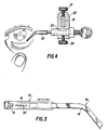
- Figure 4 illustrates the disposable unit dose tip installed on a microsyringe which is part of this device and
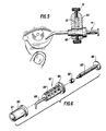
- Figure 5 illustrates the positioning of the disposable microsyringe while Figure 6 illustrates in detail the disposable syringe.
- the eyeglass- like framed drug delivery device is made up of two basic pieces, namely the bridge portion 11 and two temple pieces 16 and 17.
- the two temple pieces, 16 and 17, are hinged by means of hinges 12 to each end of the bridge piece 11 to form a typical eyeglass frame.
- Slidably mounted on each temple piece is a block 22 on which a microsyringe 31 or 41 is adjustably mounted to each block.
- FIG. 2 a detailed front view of the bridge portion of the eyeglass bridge 11.
- the nose pads 10 fit on the nose of the patient and allow said frames to rest comfortably and in a specific position when being used by the patient to administer medicament to the eyes.
- the nose pads 10 are adjustably mounted on the bridge 11 by means of a male and female dovetail joint.
- a male dovetail joint 18 At the center lower part of the bridge there is constructed a male dovetail joint 18 whereas the nose pads are constructed having a female dovetail 19.
- These dovetails are so constructed that the nose pads 10 can be slidably adjusted along the bridge 11.
- the adjustment of the nose pads in relation to the bridge is provided by a set screw 15 used to lock the nose pads to the bridge once the patient has properly positioned the nose pads. Adjustment of the nose pads compensates for the individual differences in depth which each patient's eyes are set into the skull.
- the temple pieces 16 and 17 of the drug delivery device are mounted by means of hinge assemblies 12.
- FIG. 1 and 3 show particular detail of the temple pieces 16 and 17 of the drug delivery device.
- each temple piece 16 and 17 is composed of a channel temple portion 13 which has a series of holes 19 whose center line corresponds to nibs 20 located on the sliding ear lobe portion 14 of the temple pieces 16 and 17.
- This telescoping sliding and locking action provides the mechanism of adjustment for the temple pieces.
- a person needs to adjust the temple pieces he merely pulls out or pushes in the sliding ear lobe portion 14 of the temple pieces such that the nibs 20 move along and are aligned with the various holes 19 on the channel portion 13 of the temple piece.
- the channel portion 13 of the temple piece acts as a support for the syringe block 22.
- the syringe blocks 22 are made with a hole therein of a shape slightly larger than the rectangular shape of a cross section of the channel temple portion 13 such that the block 22 can slide along the channel temple portion 13.
- the block 22 serves a double purpose in that it acts as a rigid holder for the syringe 31 or 41 and secondly it securely attaches the syringe assembly to the channel temple 13.
- thumb screws 21 on the top portion of the block 22.
- FIG. 1 shows the syringe 31 or 41 slidably mounted in the block 22.
- the syringe portions 31 or 41 are slidably mounted in the block 22 through a hole 23 in said block 22.
- the axis of the hole 23 in said block 22 is perpendicular to the longitudinal axis of the channel temple portions 13.
- the barrel of the syringe is of a diameter such that it can be slidably adjusted through the hole 23.
- a set screw 24 similar to the set screw 21 rigidly fixes the adjustment of the syringe 31 or 41. Thus, if the syringe must be moved inward toward the patient's eye one merely opens the set screws 24, adjusts the syringe and tightens the set screw 24.
- the drug delivery device herein described can generally employ two types of syringes for controlling drug delivery.
- a unit dose microsyringe 31 employs a disposable sterile tip 32 as shown in figure 4. This tip can be either preloaded with the unit dose or the microsyringe which is calibrated can be manually loaded with the unit dose.
- a disposable tip and mating microsyringe are designed so that there is only one possible alignment after mounting.
- a second type of unit disposable microsyringe 41 is completely presterilized and preloaded with a unit dose. This type of syringe is shown part 60 in figures 5 and 6.
- this second type unit disposable syringe consists of a flanged cylindrical portion 60 which rests in hole 23 in block 22 and is adjusted by set screw 24. Fitting into the body of the cylindrical portion 60 is the main syringe barrel 61. Syringe barrel 61 has on one end a flange 65 which prevents the barrel from passing through the cylindrical portion 60 and in fact forms a stop with flanged cylindrical portion 60. Barrel 61 can also have a guide 66 mounted along its length which guide moves in a depression 67 in the cylindrical portion 60 to keep the syringe and particularly the drop portion 68 on proper alignment with the patient's eye.
- Piston 63 with end portion 62 and outer flanged portion 69 forms the final part of the syringe.
- a unit dose of ophthalmic drug one merely pushes the piston until its outer flange portion 69 stops against flange 65.
- the unit dose drops out of the drop portion 68 into the patient's eye.
- the device of this invention In order to use the device of this invention one must make four adjustments before the drug solution can be administered to the eye. These include : one, adjusting the nose pads 10 so that the eye glass frame is comfortably resting on the patient's nose, secondly, adjusting the position of the block 22 on the channel temple portion 13, thirdly, adjusting the syringe 31 or 41 along the block 22 so that the tip 32 or 68 is just above the cul-de-sac of the eye when the frame is in the final position on the patient and fourth adjusting the length of the slidable temple portion 14 so that the eye glass frame comfortably fits on the patient's face being comfortable around the ears and on the nose. These adjustments do not have to be performed in the order above given but can be varied according to the preferences of the patient.
- the syringe is then used to administer the medicament or drug to the inferior cul-de-sac by the patient pulling the lower eyelid down and outside the conforming cavity to receive the medicament or drug solution liquid whereupon the plunger of the syringe is expressed expelling the contents. Once the drug has been injected into the inferior cul-de-sac the lower eyelid is released with little to no waste of the dosage.
- the ophthalmic medicaments and drug solutions which can be used in the drug delivery device of this invention can be any ophthalmic medicament or drug solution which the patient needs to administer eye drops for any ailment of the eyes.
- ophthalmic drug medicament useful for glaucoma such as timolol, propine and the like.
- Any type ophthalmic drug or medicament can be administered in this manner comfortably and once the position of the drug delivery device has been set medically no reset of any of the adjustments on the eye glass frame drug delivery device of this invention is further required.
- All the parts of the drug delivery device namely the bridge, temples, and block can be constructed of lightweight material, particularly any type plastic material commonly used for the preparation of eyeglass frames. Also, metals can be used although this would increase the cost of any drug delivery device.
- the nose pads can be made of material which would rest comfortably on the patient's nose and the end of the temples of the patient's ear can be coated with material to make the eye glass frames rest comfortably on the patient's ears.
- the syringes 31 and 41 which are used as parts of the device are typical syringes which are commonly available. There is no inventive feature in the syringe itself.
Landscapes
- Health & Medical Sciences (AREA)
- Ophthalmology & Optometry (AREA)
- General Health & Medical Sciences (AREA)
- Public Health (AREA)
- Heart & Thoracic Surgery (AREA)
- Vascular Medicine (AREA)
- Life Sciences & Earth Sciences (AREA)
- Animal Behavior & Ethology (AREA)
- Engineering & Computer Science (AREA)
- Biomedical Technology (AREA)
- Veterinary Medicine (AREA)
- Physics & Mathematics (AREA)
- General Physics & Mathematics (AREA)
- Optics & Photonics (AREA)
- Infusion, Injection, And Reservoir Apparatuses (AREA)
- Media Introduction/Drainage Providing Device (AREA)
Description
- In general, administration of ophthalmic medicaments and drug solutions to the eye has been difficult to accomplish and is generally inefficient. The most commonly employed way to administer said medicaments to the eye is to administer drops to the eye by means of an eye dropper or squeeze bottle. When this form of administration is used, the patient is required to tilt his or her head back or to lie down. This method is both messy and wasteful due to misalignment, patient blinking, inaccurate dosage and muscle control problems in many adults.
- Review of prior art has shown that F. Gorbahn (Derwent Abstract G6772W/26) developed an eye glass frame with a stationary mounting plate for the eye dropper. The device patented by A. Macha (U. S. Patent 3,446,209) April, 1966, is very similar to Gorbahn's but could also use a squeeze bottle applicator. In January, 1980, M. Meckler (U. S. Patent 4,183,355) improved on this method. He employed an eye glass frame mounted set of slides for positioning the eye dropper directly over a reclining patient's eyes. Alignment was improved. All of these devices, however, did not address the major problems of inaccurate dosage, wasteful and messy delivery.
- The particular eye glass frame mounted unit dose ophthalmic drug delivery device of this invention does innovatively address and overcome these problems and consistently delivers an exact unit dosage of ophthalmic medicament or drug to the inferior cul-de-sac of the eye.
- The advantages of our ophthalmic drug delivery device as defined in Claims 1 to 6 are several.
- 1) The patient uses a unit dose medication that has been preloaded for exact dosage and there is no spilling of contents or inaccurate dose measurements as in the old systems whereby the drops could have run out of the eye or not even gotten into the eye.
- 2) The eyeglass frame mounted unit dose ophthalmic drug delivery device of our invention is universally adjustable so that after the initial setting the patient does not need to readjust the frames.
- 3) The patient's head remains erect and the ophthalmic medication or drug solution is delivered directly into the inferior cul-de-sac of the eye thus eliminating any problems of said drug or solution running out of the eye.
- 4) Many older patients who lack muscle control will be able to use this device effectively since once it is adjusted to the patients physical feature it is rather easy to administer the ophthalmic drug or medication to the eye.
- Thus it is an object of this invention to provide an ophthalmic drug delivery system which will deliver a unit dosage to the inferior cul-de-sac of the eye. It is a further object of this invention to provide an ophthalmic drug delivery device, that is universally adjustable to fit all patients and that once an initial setting is made no further adjustments are needed or warranted. It is a further object of this invention to provide a device wherein the patient's head is in an erect position while the dose is administered to the inferior cul-de-sac of the eye and to provide a patient with a great deal more flexibility than is known in the prior devices and particularly in self-dosing and in cutting down of wasted medication.
- To provide a better understanding of this invention there are provided six figures showing the various embodiments of the invention. Figure 1 is an isometric view illustrating the assembly of the complete ophthalmic drug delivery device. Figure 2 is a detailed illustration of the adjustable bridge feature with repositionable nose pads of this device. Figure 3 is a detailed drawing of the adjustable temple piece of the drug delivery device. Figure 4 illustrates the disposable unit dose tip installed on a microsyringe which is part of this device and Figure 5 illustrates the positioning of the disposable microsyringe while Figure 6 illustrates in detail the disposable syringe.
- Referring now to the figures, particularly Figure 1, there is shown a frame mounted unit dose ophthalmic drug delivery device 1. The eyeglass- like framed drug delivery device is made up of two basic pieces, namely the bridge portion 11 and two
temple pieces hinges 12 to each end of the bridge piece 11 to form a typical eyeglass frame. Slidably mounted on each temple piece is ablock 22 on which a microsyringe 31 or 41 is adjustably mounted to each block. - Referring now in detail to each particular part of the eyeglass frame drug delivery device, there is shown in Figure 2 a detailed front view of the bridge portion of the eyeglass bridge 11. On the bridge 11 are shown built-in
adjustable nose pads 10 mounted on the lower part of the bridge 11 at about its central area. The nose pads 10 fit on the nose of the patient and allow said frames to rest comfortably and in a specific position when being used by the patient to administer medicament to the eyes. Thenose pads 10 are adjustably mounted on the bridge 11 by means of a male and female dovetail joint. At the center lower part of the bridge there is constructed amale dovetail joint 18 whereas the nose pads are constructed having afemale dovetail 19. These dovetails are so constructed that thenose pads 10 can be slidably adjusted along the bridge 11. The adjustment of the nose pads in relation to the bridge is provided by aset screw 15 used to lock the nose pads to the bridge once the patient has properly positioned the nose pads. Adjustment of the nose pads compensates for the individual differences in depth which each patient's eyes are set into the skull. At each end of the bridge 11 thetemple pieces hinge assemblies 12. - Figure 1 and 3 show particular detail of the
temple pieces temple piece channel temple portion 13 which has a series ofholes 19 whose center line corresponds tonibs 20 located on the slidingear lobe portion 14 of thetemple pieces ear lobe portion 14 of the temple pieces such that thenibs 20 move along and are aligned with thevarious holes 19 on thechannel portion 13 of the temple piece. - As shown in figures 1, 4 and 5 the
channel portion 13 of the temple piece acts as a support for thesyringe block 22. Thus thesyringe blocks 22 are made with a hole therein of a shape slightly larger than the rectangular shape of a cross section of thechannel temple portion 13 such that theblock 22 can slide along thechannel temple portion 13. Theblock 22 serves a double purpose in that it acts as a rigid holder for the syringe 31 or 41 and secondly it securely attaches the syringe assembly to thechannel temple 13. - In order to adjust the
blocks 22 in a position convenient to administer the medicament or drug solution to the patient's eye there are providedthumb screws 21 on the top portion of theblock 22. To adjust the block along thechannel temple portion 13 one merely opens thethumb screw 21 moves the block to the desired position and tightens thethumb screw 21. Tightening the thumb screw against thetemple portion 13 rigidly sets the block in the desired position. - As a final portion to the eye glass frame drug delivery device figures 1, 4, 5 and 6 show the syringe 31 or 41 slidably mounted in the
block 22. The syringe portions 31 or 41 are slidably mounted in theblock 22 through ahole 23 in saidblock 22. The axis of thehole 23 in saidblock 22 is perpendicular to the longitudinal axis of thechannel temple portions 13. The barrel of the syringe is of a diameter such that it can be slidably adjusted through thehole 23. Aset screw 24 similar to theset screw 21 rigidly fixes the adjustment of the syringe 31 or 41. Thus, if the syringe must be moved inward toward the patient's eye one merely opens the setscrews 24, adjusts the syringe and tightens theset screw 24. - The drug delivery device herein described can generally employ two types of syringes for controlling drug delivery. First a unit dose microsyringe 31 employs a disposable
sterile tip 32 as shown in figure 4. This tip can be either preloaded with the unit dose or the microsyringe which is calibrated can be manually loaded with the unit dose. A disposable tip and mating microsyringe are designed so that there is only one possible alignment after mounting. - A second type of unit disposable microsyringe 41 is completely presterilized and preloaded with a unit dose. This type of syringe is shown
part 60 in figures 5 and 6. - As shown in figures 5 and 6 this second type unit disposable syringe consists of a flanged
cylindrical portion 60 which rests inhole 23 inblock 22 and is adjusted by setscrew 24. Fitting into the body of thecylindrical portion 60 is themain syringe barrel 61.Syringe barrel 61 has on one end a flange 65 which prevents the barrel from passing through thecylindrical portion 60 and in fact forms a stop with flangedcylindrical portion 60.Barrel 61 can also have aguide 66 mounted along its length which guide moves in adepression 67 in thecylindrical portion 60 to keep the syringe and particularly thedrop portion 68 on proper alignment with the patient's eye.Piston 63 withend portion 62 and outerflanged portion 69 forms the final part of the syringe. Thus to administer a unit dose of ophthalmic drug one merely pushes the piston until itsouter flange portion 69 stops against flange 65. The unit dose drops out of thedrop portion 68 into the patient's eye. - In order to use the device of this invention one must make four adjustments before the drug solution can be administered to the eye. These include : one, adjusting the
nose pads 10 so that the eye glass frame is comfortably resting on the patient's nose, secondly, adjusting the position of theblock 22 on thechannel temple portion 13, thirdly, adjusting the syringe 31 or 41 along theblock 22 so that thetip slidable temple portion 14 so that the eye glass frame comfortably fits on the patient's face being comfortable around the ears and on the nose. These adjustments do not have to be performed in the order above given but can be varied according to the preferences of the patient. Once the preferred orientation of the ophthalmic drug delivery device to the eye is reached no further adjustments will be necessary. The syringe is then used to administer the medicament or drug to the inferior cul-de-sac by the patient pulling the lower eyelid down and outside the conforming cavity to receive the medicament or drug solution liquid whereupon the plunger of the syringe is expressed expelling the contents. Once the drug has been injected into the inferior cul-de-sac the lower eyelid is released with little to no waste of the dosage. - The ophthalmic medicaments and drug solutions which can be used in the drug delivery device of this invention can be any ophthalmic medicament or drug solution which the patient needs to administer eye drops for any ailment of the eyes. Thus for example if the patient has glaucoma he can administer ophthalmic drug medicament useful for glaucoma such as timolol, propine and the like. Anyone skilled in the art would realize that any type ophthalmic drug or medicament can be administered in this manner comfortably and once the position of the drug delivery device has been set medically no reset of any of the adjustments on the eye glass frame drug delivery device of this invention is further required.
- All the parts of the drug delivery device, namely the bridge, temples, and block can be constructed of lightweight material, particularly any type plastic material commonly used for the preparation of eyeglass frames. Also, metals can be used although this would increase the cost of any drug delivery device. Typically, the nose pads can be made of material which would rest comfortably on the patient's nose and the end of the temples of the patient's ear can be coated with material to make the eye glass frames rest comfortably on the patient's ears. The syringes 31 and 41 which are used as parts of the device are typical syringes which are commonly available. There is no inventive feature in the syringe itself.
- The above is a description of the invention as defined by the claims and should be considered an illustration of the invention and not be considered a limitation thereof.
Claims (6)
Applications Claiming Priority (2)
| Application Number | Priority Date | Filing Date | Title |
|---|---|---|---|
| US06/550,427 US4573982A (en) | 1983-11-10 | 1983-11-10 | Eye frame ophthalmic drug delivery device |
| US550427 | 1983-11-10 |
Publications (2)
| Publication Number | Publication Date |
|---|---|
| EP0145541A1 EP0145541A1 (en) | 1985-06-19 |
| EP0145541B1 true EP0145541B1 (en) | 1987-03-25 |
Family
ID=24197143
Family Applications (1)
| Application Number | Title | Priority Date | Filing Date |
|---|---|---|---|
| EP84402219A Expired EP0145541B1 (en) | 1983-11-10 | 1984-11-06 | Eye frame ophthalmic drug delivery device |
Country Status (4)
| Country | Link |
|---|---|
| US (1) | US4573982A (en) |
| EP (1) | EP0145541B1 (en) |
| JP (1) | JPS60116371A (en) |
| DE (1) | DE3462750D1 (en) |
Families Citing this family (27)
| Publication number | Priority date | Publication date | Assignee | Title |
|---|---|---|---|---|
| GB8710664D0 (en) * | 1987-05-06 | 1987-06-10 | Scras | Self-administration of ocular treatment materials |
| US4981479A (en) * | 1987-11-06 | 1991-01-01 | Py Daniel C | Ocular treatment apparatus |
| US5133702A (en) * | 1987-11-06 | 1992-07-28 | O.P.T.I.C. | Ocular treatment apparatus |
| US4908024A (en) * | 1988-05-04 | 1990-03-13 | Py Daniel C | Ocular self-treatment apparatus and method |
| US5163929A (en) * | 1989-03-13 | 1992-11-17 | O.P.T.I.C., Inc. | Ocular vial |
| US5085651A (en) * | 1989-03-13 | 1992-02-04 | Py Daniel C | Ocular vial |
| US5368582A (en) * | 1992-08-10 | 1994-11-29 | The Schepens Eye Research Institute | Method and apparatus for introducing fluid material into an eye |
| US5807357A (en) * | 1997-08-19 | 1998-09-15 | Kang; Meng-Che | Compact nebulizer for treating the eyes |
| US8128606B2 (en) * | 2003-07-03 | 2012-03-06 | Hewlett-Packard Development Company, L.P. | Ophthalmic apparatus and method for administering agents to the eye |
| US20060092678A1 (en) * | 2004-11-02 | 2006-05-04 | Nec Electronics Corporation | Apparatus and method for power conversion |
| US20080233053A1 (en) * | 2005-02-07 | 2008-09-25 | Pharmalight Inc. | Method and Device for Ophthalmic Administration of Active Pharmaceutical Ingredients |
| GB0516106D0 (en) * | 2005-08-05 | 2005-09-14 | Ian Harrison Associates | Applicator |
| US20070286890A1 (en) * | 2006-06-07 | 2007-12-13 | John Garnett Walt | Eyelash applicator and method |
| US20110181832A1 (en) * | 2009-01-16 | 2011-07-28 | Brian Patrick Smith | Eyewear system for the treatment of unilateral neglect syndrome |
| US7824372B1 (en) | 2009-05-13 | 2010-11-02 | Kurup Shree K | Syringe guide and shield for use in administering ophthalmologic injections |
| US8147467B2 (en) * | 2009-09-24 | 2012-04-03 | Stephen C Chen | Noninvasive lacrimal canalicular occlusion device and method |
| US8348912B2 (en) * | 2009-10-22 | 2013-01-08 | Anakin Llc | Eye dropper alignment apparatus and method for using same |
| US9033941B2 (en) | 2009-10-22 | 2015-05-19 | Anakin Llc | Eye dropper alignment apparatus and method for using same |
| US20110118678A1 (en) * | 2009-10-22 | 2011-05-19 | Jeffrey Rehkemper | Condensed eye dropper alignment apparatus and method for using same |
| WO2015123656A1 (en) * | 2014-02-17 | 2015-08-20 | University Of Florida Research Foundation, Inc. | Automated eye drop instillation |
| EP4173550A1 (en) | 2015-03-16 | 2023-05-03 | Magic Leap, Inc. | Diagnosing and treating health ailments |
| CA3019946C (en) | 2016-04-08 | 2023-02-28 | Magic Leap, Inc. | Augmented reality systems and methods with variable focus lens elements |
| US9539170B1 (en) | 2016-08-22 | 2017-01-10 | Hamdah J. S. Adaie | Lacrimal duct therapy device |
| EP3586187B1 (en) | 2017-02-23 | 2024-01-03 | Magic Leap, Inc. | Display system with variable power reflector |
| CN111920574B (en) * | 2020-08-21 | 2021-04-27 | 永目堂股份有限公司 | A device for automatically instilling eye drops before eye examination |
| US11647942B1 (en) | 2022-03-22 | 2023-05-16 | Stat Capsule Inc. | Device for monitoring and treating bradyarrhythmia |
| US11471657B1 (en) | 2022-03-22 | 2022-10-18 | Stat Capsule Inc. | Device and method for monitoring and treating advanced bradycardia |
Family Cites Families (5)
| Publication number | Priority date | Publication date | Assignee | Title |
|---|---|---|---|---|
| US3209755A (en) * | 1961-02-03 | 1965-10-05 | Avco Corp | Nasal catheter holder |
| US3446209A (en) * | 1966-04-07 | 1969-05-27 | August Macha | Device for facilitating self-introduction of medicinal drops in eyes |
| US3934585A (en) * | 1970-08-13 | 1976-01-27 | Maurice David M | Method and apparatus for application of eye drops |
| DE2550254C3 (en) * | 1975-11-08 | 1978-05-03 | Fritz Dr.Med. 5810 Witten Gorbahn | Auxiliary device for use when instilling eye drops |
| US4183355A (en) * | 1978-02-02 | 1980-01-15 | Milton Meckler | Eye medication dispensing frames |
-
1983
- 1983-11-10 US US06/550,427 patent/US4573982A/en not_active Expired - Fee Related
-
1984
- 1984-11-06 EP EP84402219A patent/EP0145541B1/en not_active Expired
- 1984-11-06 DE DE8484402219T patent/DE3462750D1/en not_active Expired
- 1984-11-09 JP JP59235345A patent/JPS60116371A/en active Pending
Also Published As
| Publication number | Publication date |
|---|---|
| EP0145541A1 (en) | 1985-06-19 |
| US4573982A (en) | 1986-03-04 |
| DE3462750D1 (en) | 1987-04-30 |
| JPS60116371A (en) | 1985-06-22 |
Similar Documents
| Publication | Publication Date | Title |
|---|---|---|
| US4573982A (en) | Eye frame ophthalmic drug delivery device | |
| US4908024A (en) | Ocular self-treatment apparatus and method | |
| US6197008B1 (en) | Precise instilation eye dropper tip | |
| US5848999A (en) | Dispensing eye drops | |
| EP1891942B1 (en) | Opthalmic insert and method for sustained release of medication to the eye | |
| US5354335A (en) | Intraocular insert for implantation in the human eye | |
| US7527613B2 (en) | Therapeutic solution drop dispenser | |
| US5129717A (en) | Adjustable telescopic alignment apparatus for use with a carrier lens | |
| USRE28873E (en) | Scleral lens with attached tube | |
| US8348912B2 (en) | Eye dropper alignment apparatus and method for using same | |
| US4183355A (en) | Eye medication dispensing frames | |
| US3664340A (en) | Scleral lens with attached tube | |
| US5665069A (en) | Pressure-directed peribulbar anesthesia delivery device | |
| US9033941B2 (en) | Eye dropper alignment apparatus and method for using same | |
| DE69828275T2 (en) | LIQUID APPLICATOR FOR THE EYES | |
| Hanna et al. | Ocular penetration of topical chloramphenicol in humans | |
| CN114173723A (en) | Eye drop administration system | |
| JP2673537B2 (en) | Ocular treatment substance self-administration device | |
| CN108743008B (en) | Auxiliary self-help dual-purpose eye dropper | |
| CN209661952U (en) | A kind of auxiliary device for putting eyedrops in eyes | |
| DE10250473A1 (en) | Aid for administering medication or another substance into the eye comprises a spectacle-shaped holder provided with an adapter for a container that is arranged on the holder so that an end region is arranged a distance away from the eye | |
| US7478850B2 (en) | Ocular device | |
| CN214805947U (en) | Drug delivery device for clinical diagnosis and treatment of ophthalmology | |
| US20230056572A1 (en) | Eye drop dispenser assembly | |
| EP3900683A1 (en) | Cannula and container of ophthalmic solutions |
Legal Events
| Date | Code | Title | Description |
|---|---|---|---|
| PUAI | Public reference made under article 153(3) epc to a published international application that has entered the european phase |
Free format text: ORIGINAL CODE: 0009012 |
|
| AK | Designated contracting states |
Designated state(s): CH DE FR GB IT LI NL |
|
| ITCL | It: translation for ep claims filed |
Representative=s name: SOCIETA' ITALIANA BREVETTI S.P.A. |
|
| 17P | Request for examination filed |
Effective date: 19850829 |
|
| 17Q | First examination report despatched |
Effective date: 19860709 |
|
| GRAA | (expected) grant |
Free format text: ORIGINAL CODE: 0009210 |
|
| AK | Designated contracting states |
Kind code of ref document: B1 Designated state(s): CH DE FR GB IT LI NL |
|
| REF | Corresponds to: |
Ref document number: 3462750 Country of ref document: DE Date of ref document: 19870430 |
|
| ET | Fr: translation filed | ||
| ITF | It: translation for a ep patent filed | ||
| PLBE | No opposition filed within time limit |
Free format text: ORIGINAL CODE: 0009261 |
|
| STAA | Information on the status of an ep patent application or granted ep patent |
Free format text: STATUS: NO OPPOSITION FILED WITHIN TIME LIMIT |
|
| 26N | No opposition filed | ||
| ITTA | It: last paid annual fee | ||
| PGFP | Annual fee paid to national office [announced via postgrant information from national office to epo] |
Ref country code: CH Payment date: 19920917 Year of fee payment: 9 |
|
| PGFP | Annual fee paid to national office [announced via postgrant information from national office to epo] |
Ref country code: FR Payment date: 19920924 Year of fee payment: 9 |
|
| PGFP | Annual fee paid to national office [announced via postgrant information from national office to epo] |
Ref country code: GB Payment date: 19921001 Year of fee payment: 9 |
|
| PGFP | Annual fee paid to national office [announced via postgrant information from national office to epo] |
Ref country code: DE Payment date: 19921126 Year of fee payment: 9 |
|
| PGFP | Annual fee paid to national office [announced via postgrant information from national office to epo] |
Ref country code: NL Payment date: 19921130 Year of fee payment: 9 |
|
| PG25 | Lapsed in a contracting state [announced via postgrant information from national office to epo] |
Ref country code: GB Effective date: 19931106 |
|
| PG25 | Lapsed in a contracting state [announced via postgrant information from national office to epo] |
Ref country code: LI Effective date: 19931130 Ref country code: CH Effective date: 19931130 |
|
| PG25 | Lapsed in a contracting state [announced via postgrant information from national office to epo] |
Ref country code: NL Effective date: 19940601 |
|
| GBPC | Gb: european patent ceased through non-payment of renewal fee |
Effective date: 19931106 |
|
| NLV4 | Nl: lapsed or anulled due to non-payment of the annual fee | ||
| PG25 | Lapsed in a contracting state [announced via postgrant information from national office to epo] |
Ref country code: FR Effective date: 19940729 |
|
| REG | Reference to a national code |
Ref country code: CH Ref legal event code: PL |
|
| PG25 | Lapsed in a contracting state [announced via postgrant information from national office to epo] |
Ref country code: DE Effective date: 19940802 |
|
| REG | Reference to a national code |
Ref country code: FR Ref legal event code: ST |