EP0145516B1 - Cutting device and method for the precision trimming of the edge of a cast contact lens - Google Patents
Cutting device and method for the precision trimming of the edge of a cast contact lens Download PDFInfo
- Publication number
- EP0145516B1 EP0145516B1 EP84401827A EP84401827A EP0145516B1 EP 0145516 B1 EP0145516 B1 EP 0145516B1 EP 84401827 A EP84401827 A EP 84401827A EP 84401827 A EP84401827 A EP 84401827A EP 0145516 B1 EP0145516 B1 EP 0145516B1
- Authority
- EP
- European Patent Office
- Prior art keywords
- cutting
- edge
- male mold
- contact lens
- lens
- Prior art date
- Legal status (The legal status is an assumption and is not a legal conclusion. Google has not performed a legal analysis and makes no representation as to the accuracy of the status listed.)
- Expired
Links
Images


Classifications
-
- B—PERFORMING OPERATIONS; TRANSPORTING
- B29—WORKING OF PLASTICS; WORKING OF SUBSTANCES IN A PLASTIC STATE IN GENERAL
- B29D—PRODUCING PARTICULAR ARTICLES FROM PLASTICS OR FROM SUBSTANCES IN A PLASTIC STATE
- B29D11/00—Producing optical elements, e.g. lenses or prisms
- B29D11/00932—Combined cutting and grinding thereof
- B29D11/00942—Combined cutting and grinding thereof where the lens material is mounted in a support for mounting onto a cutting device, e.g. a lathe, and where the support is of machinable material, e.g. plastics
-
- B—PERFORMING OPERATIONS; TRANSPORTING
- B29—WORKING OF PLASTICS; WORKING OF SUBSTANCES IN A PLASTIC STATE IN GENERAL
- B29C—SHAPING OR JOINING OF PLASTICS; SHAPING OF MATERIAL IN A PLASTIC STATE, NOT OTHERWISE PROVIDED FOR; AFTER-TREATMENT OF THE SHAPED PRODUCTS, e.g. REPAIRING
- B29C37/00—Component parts, details, accessories or auxiliary operations, not covered by group B29C33/00 or B29C35/00
- B29C37/02—Deburring or deflashing
-
- B—PERFORMING OPERATIONS; TRANSPORTING
- B29—WORKING OF PLASTICS; WORKING OF SUBSTANCES IN A PLASTIC STATE IN GENERAL
- B29D—PRODUCING PARTICULAR ARTICLES FROM PLASTICS OR FROM SUBSTANCES IN A PLASTIC STATE
- B29D11/00—Producing optical elements, e.g. lenses or prisms
- B29D11/00009—Production of simple or compound lenses
- B29D11/00038—Production of contact lenses
-
- B—PERFORMING OPERATIONS; TRANSPORTING
- B29—WORKING OF PLASTICS; WORKING OF SUBSTANCES IN A PLASTIC STATE IN GENERAL
- B29D—PRODUCING PARTICULAR ARTICLES FROM PLASTICS OR FROM SUBSTANCES IN A PLASTIC STATE
- B29D11/00—Producing optical elements, e.g. lenses or prisms
- B29D11/00009—Production of simple or compound lenses
- B29D11/0048—Moulds for lenses
-
- Y—GENERAL TAGGING OF NEW TECHNOLOGICAL DEVELOPMENTS; GENERAL TAGGING OF CROSS-SECTIONAL TECHNOLOGIES SPANNING OVER SEVERAL SECTIONS OF THE IPC; TECHNICAL SUBJECTS COVERED BY FORMER USPC CROSS-REFERENCE ART COLLECTIONS [XRACs] AND DIGESTS
- Y10—TECHNICAL SUBJECTS COVERED BY FORMER USPC
- Y10T—TECHNICAL SUBJECTS COVERED BY FORMER US CLASSIFICATION
- Y10T408/00—Cutting by use of rotating axially moving tool
- Y10T408/83—Tool-support with means to move Tool relative to tool-support
- Y10T408/85—Tool-support with means to move Tool relative to tool-support to move radially
- Y10T408/858—Moving means including wedge, screw or cam
- Y10T408/8595—Pivotable tool-support
-
- Y—GENERAL TAGGING OF NEW TECHNOLOGICAL DEVELOPMENTS; GENERAL TAGGING OF CROSS-SECTIONAL TECHNOLOGIES SPANNING OVER SEVERAL SECTIONS OF THE IPC; TECHNICAL SUBJECTS COVERED BY FORMER USPC CROSS-REFERENCE ART COLLECTIONS [XRACs] AND DIGESTS
- Y10—TECHNICAL SUBJECTS COVERED BY FORMER USPC
- Y10T—TECHNICAL SUBJECTS COVERED BY FORMER US CLASSIFICATION
- Y10T408/00—Cutting by use of rotating axially moving tool
- Y10T408/86—Tool-support with means to permit positioning of the Tool relative to support
- Y10T408/865—Pivotable Tool
-
- Y—GENERAL TAGGING OF NEW TECHNOLOGICAL DEVELOPMENTS; GENERAL TAGGING OF CROSS-SECTIONAL TECHNOLOGIES SPANNING OVER SEVERAL SECTIONS OF THE IPC; TECHNICAL SUBJECTS COVERED BY FORMER USPC CROSS-REFERENCE ART COLLECTIONS [XRACs] AND DIGESTS
- Y10—TECHNICAL SUBJECTS COVERED BY FORMER USPC
- Y10T—TECHNICAL SUBJECTS COVERED BY FORMER US CLASSIFICATION
- Y10T409/00—Gear cutting, milling, or planing
- Y10T409/30—Milling
- Y10T409/303752—Process
- Y10T409/303808—Process including infeeding
-
- Y—GENERAL TAGGING OF NEW TECHNOLOGICAL DEVELOPMENTS; GENERAL TAGGING OF CROSS-SECTIONAL TECHNOLOGIES SPANNING OVER SEVERAL SECTIONS OF THE IPC; TECHNICAL SUBJECTS COVERED BY FORMER USPC CROSS-REFERENCE ART COLLECTIONS [XRACs] AND DIGESTS
- Y10—TECHNICAL SUBJECTS COVERED BY FORMER USPC
- Y10T—TECHNICAL SUBJECTS COVERED BY FORMER US CLASSIFICATION
- Y10T409/00—Gear cutting, milling, or planing
- Y10T409/30—Milling
- Y10T409/304144—Means to trim edge
-
- Y—GENERAL TAGGING OF NEW TECHNOLOGICAL DEVELOPMENTS; GENERAL TAGGING OF CROSS-SECTIONAL TECHNOLOGIES SPANNING OVER SEVERAL SECTIONS OF THE IPC; TECHNICAL SUBJECTS COVERED BY FORMER USPC CROSS-REFERENCE ART COLLECTIONS [XRACs] AND DIGESTS
- Y10—TECHNICAL SUBJECTS COVERED BY FORMER USPC
- Y10T—TECHNICAL SUBJECTS COVERED BY FORMER US CLASSIFICATION
- Y10T409/00—Gear cutting, milling, or planing
- Y10T409/30—Milling
- Y10T409/306216—Randomly manipulated, work supported, or work following device
- Y10T409/306552—Randomly manipulated
-
- Y—GENERAL TAGGING OF NEW TECHNOLOGICAL DEVELOPMENTS; GENERAL TAGGING OF CROSS-SECTIONAL TECHNOLOGIES SPANNING OVER SEVERAL SECTIONS OF THE IPC; TECHNICAL SUBJECTS COVERED BY FORMER USPC CROSS-REFERENCE ART COLLECTIONS [XRACs] AND DIGESTS
- Y10—TECHNICAL SUBJECTS COVERED BY FORMER USPC
- Y10T—TECHNICAL SUBJECTS COVERED BY FORMER US CLASSIFICATION
- Y10T409/00—Gear cutting, milling, or planing
- Y10T409/30—Milling
- Y10T409/306664—Milling including means to infeed rotary cutter toward work
- Y10T409/306776—Axially
- Y10T409/306832—Axially with infeed control means energized in response to activator stimulated by condition sensor
- Y10T409/306944—In response to work condition
-
- Y—GENERAL TAGGING OF NEW TECHNOLOGICAL DEVELOPMENTS; GENERAL TAGGING OF CROSS-SECTIONAL TECHNOLOGIES SPANNING OVER SEVERAL SECTIONS OF THE IPC; TECHNICAL SUBJECTS COVERED BY FORMER USPC CROSS-REFERENCE ART COLLECTIONS [XRACs] AND DIGESTS
- Y10—TECHNICAL SUBJECTS COVERED BY FORMER USPC
- Y10T—TECHNICAL SUBJECTS COVERED BY FORMER US CLASSIFICATION
- Y10T409/00—Gear cutting, milling, or planing
- Y10T409/30—Milling
- Y10T409/308624—Milling with limit means to aid in positioning of cutter bit or work [e.g., gauge, stop, etc.]
-
- Y—GENERAL TAGGING OF NEW TECHNOLOGICAL DEVELOPMENTS; GENERAL TAGGING OF CROSS-SECTIONAL TECHNOLOGIES SPANNING OVER SEVERAL SECTIONS OF THE IPC; TECHNICAL SUBJECTS COVERED BY FORMER USPC CROSS-REFERENCE ART COLLECTIONS [XRACs] AND DIGESTS
- Y10—TECHNICAL SUBJECTS COVERED BY FORMER USPC
- Y10T—TECHNICAL SUBJECTS COVERED BY FORMER US CLASSIFICATION
- Y10T82/00—Turning
- Y10T82/10—Process of turning
-
- Y—GENERAL TAGGING OF NEW TECHNOLOGICAL DEVELOPMENTS; GENERAL TAGGING OF CROSS-SECTIONAL TECHNOLOGIES SPANNING OVER SEVERAL SECTIONS OF THE IPC; TECHNICAL SUBJECTS COVERED BY FORMER USPC CROSS-REFERENCE ART COLLECTIONS [XRACs] AND DIGESTS
- Y10—TECHNICAL SUBJECTS COVERED BY FORMER USPC
- Y10T—TECHNICAL SUBJECTS COVERED BY FORMER US CLASSIFICATION
- Y10T82/00—Turning
- Y10T82/14—Axial pattern
- Y10T82/148—Pivoted tool rest
Definitions
- the present invention relates to a cutting device for precision trimming a selected portion of the peripheral edge of a cast contact lens secured within a flexible circumferential rim on the exter- . nal surfaces of a male mold.
- the invention also relates to a method for the economical and precision trimming of a selected portion of the peripheral edge of a cast contact lens secured within a circumferential rim on the external surface of a male mold.
- US-A-3295417 discloses an apparatus for cutting optical elements such as lenses for sunglasses. Such an apparatus cannot be used for trimming the edge of contact lenses, said trimming presenting problems unlike those which exist for conventional glass lenses which are to be mounted on a frame.
- a widely practiced technique for the manufacture of soft contact lenses involves the lathing procedure (DE-A 2102820).
- This technique has many drawbacks inasmuch as it is a labor intensive operation, requires several steps, is relatively expensive, and the finished lens product is characterized by striations on its optical surfaces.
- an appropriate polymerization medium is first polymerized into a cylindrical shape from which there are cut so-calldd-lens "buttons" or lens blanks, or the lens blanks perse can be made in appropriate molds.
- the blanks are subjected to a postcure treatment to improve certain of their physical characteristics.
- a pre- determined curved surface is thereafter cut on one face of the blank by using precision lathe machinery and the cut curved surface is polished to an optical surface.
- Formation of an optical surface on the opposite face of the blank requires adhering the partially cut blank to an arbor or mandrel by means of a waxy substance in a manner that the uncut face of the blank is exposed for the lathing and polishing operations. Thereafter, there are washing and cleaning steps to remove residues from the cutting and polishing procedures and eventually, as with soft contact lenses, soaking in a physiologic solution until osmotic equilibrium is reached at which stage the hydrogel lens attains its final dimensions.
- This method suffers from the disadvantage of requiring highly skilled artisans for quality production.
- the inevitable shrinkage that occurs on polymerization can result in surface and/or edge irregularity of the cast lenses.
- the volumetric shrinkage during polymerization can be as high as 22%. This degree of shrinkage will generally prevent satisfactory casting of soft contact lenses where surface finish and sharpe are important.
- a polymerizable acrylate, or methacrylate ester mixture held in a closed glass mold invariably would pull away from at least one mold surface and cause the formation of surface voids which render the cast lines unsuitable for use as a contact lens for humans.
- the lens-forming material contracts causing the flexible rim to flex, inwardly usually, whereby the two mold members move towards each other.
- the mold members are separated and the resulting contact lens is secured within the circumferential rim on the mold.
- the lens can then be removed in a condition ready for use, except for cleaning and perhaps a buffing of the lens edge.
- Objects of the invention are for the provision of novel cutting devices and novel methods for symmetrically trimming the peripheral edge portion of a cast lens.
- Another object of the invention is to provide a novel cutting device employing guiding means associated with cutting means for the precision trimming of a selected portion of the peripheral edge of a soft contact lens.
- Yet another object of the invention is to provide a novel cutting device employing guiding means associated with cutting means and utilizing fiber optic means for detecting when the selected portion of the peripheral edge of a cast soft contact lens is in position to be trimmed.
- Another additional object of the invention is to provide a novel cutting device employing guiding means associated with cutting means and utilizing air gage sensing means for detecting when the selected portion of the peripheral edge of a cast soft contact lens is in position to be trimmed.
- Still another object of the invention is to provide a method for the precision trimming of a selected portion of the peripheral edge of a cast soft contact lens which is not labor intensive or capital intensive, which can be operated in an efficient manner on a continuous basis, which is relatively small in size as to be readily portable and/or obviates various disadvantages of the art.
- the invention relates to a cutting device for trimming a selected peripheral edge portion of a contact lens secured in a male mold, which cutting device comprises a housing having an extended support member; a cutting means having a cutting edge and said cutting means secured to said support member; said support member having a guiding edge disposed a fixed distance from said cutting edge; and said guiding edge and said cutting edge being cooperatively associated so that when said guiding edge contacts the outer wall of a male mold, the cutting edge will be positioned for the precision trimming of an edge portion of a contact lens secured on the male mold.
- a symmetrical and precision trimming of a selected portion of the peripheral edge of a contact lens secured on a male mold can be performed.
- the cutting edge will be precisely positioned for trimming a preselected portion of the peripheral edge of a contact lens secured on the male mold.
- the guiding edge will ride on the outer wall of the male mold thereby insuring that the cutting edge is positioned for selectively trimming a precise segment of the edge of the contact lens.
- This guiding edge and cutting edge arrangement will compensate for any eccentricity that may exist between the opening defined in the male mold which is adapted to receive a conventional rotating mandrel and the outer diameter of the male mold.
- the cutting edge will impart a precision trim to the peripheral edge portion of the contact lens such that the cut of the lens is concentric with the outer diameter of the lens and independent of any eccentricity that may exist between the opening defined in the mold and the outer diameter of the mold.
- the extended support member should be pivotable with respect to the housing of the device so that the housing could remain fixed while the extended support member and cutting means secured thereon would be free to follow any run-out created by any eccentricity between the outer diameter of the male mold and the hole defined in the center of the male mold.
- Another preferred feature of the invention is to have the cutting means adjustably mounted on the support member so that the distance between the cutting edge and the guiding edge can be adjusted to accommodate different size molds.
- the cutting means should be easily disassembled from the cutting device to facilitate the sharpening of the cutting edge when desired or to replace the cutting edge when necessary.
- the cutting edge comprises a sharp segment and a blunt segment such that the sharp segment could be positioned to precision trim the contact lens while the blunt segment could be positioned to slide upon the circumferential rim of the male mold that secures the contact lens to the mold.
- the guiding edge of the support member could be appropriately curved to conform to the contour of the wall of the mold so as to facilitate the sliding of the guiding edge on the mold.
- An additional embodiment of the invention would entail the use of fiber optics means or air gage sensing means in the novel cutting device to detect when the cutting edge is properly distanced from the contact lens so that the extremely accurate trimming of the lens edge can be accomplished. Since the male mold will be rotating at the same speed as the mandrel, the detection of the precise position that trimming of the lens will occur by the fiber optic means or air gage sensing means will provide a signal which will cause the advancing cutting device to stop whereupon the lens trimming operation will be accomplished. The male mold can be taken off the mandrel and the contact lens can then be removed in a condition ready for use, except for cleaning and perhaps a buffing of the lens edge. Due to the small size of contact lenses and specifically to the extremely small size of the edge portion of the lens to be trimmed, it is rather difficult to determine when and if trimming has been completed.
- the cutting device can be used on a continuous operation to produce contact lenses to exact physical specifications in a minimum of time since the fiber optic means or air gage sensing means will insure when the trimming of the lens has commenced.
- Conventional fiber optic means can be used in conjunction with the novel cutting device of this invention.
- the distal end of a fiber bundle (for example, from an optical extender coupled to a fiber optic probe) is placed in close proxomity to where the reflected surface of the lens in the male mold would be positioned to be trimmed by the cutting edge of the cutting means.
- Light traveling down the fiber bundle is reflected from the contact lens surface back onto receive fibers of the bundle located in a conventional probe tip and such reflection is detected by a photo sensor.
- the amount of reflected light is related to the distance between the face of the fibers and the reflected surface, the acceptance angle, or numerical aperture of the fibers, and the reflectivity of the surface.
- the fiber optic means can be used as a convenient prox- imitor for generating a signal to stop the advancing cutting device when the contact lens surface is precisely positioned for trimming by the cutting edge of the cutting means.
- a signal can be generated to automatically remove the cutting device to another rotating male mold on a mandrel thus providing a continuous operation for trimming the edge of cast lenses.
- Conventional air gage sensing means can be used in conjunction with the novel cutting device of this invention.
- Commercial air gage sensing means can be obtained from Edmunds Manufacturing Company, Farmington Industrial Park, Farmington, Connecticut 06032.
- air from a regulated supply will flow through a restriction device coupled to an output nozzle.
- the air flow will be restricted and pressure down stream of the restriction device will gradually build up until it is the same as the regulated supply.
- the exact distance of the object from the end of the nozzle can be detected by measuring the change of air flow and the change of pressure.
- air gage sensing means can be used as a convenient proximeter for generating a signal to stop the advancing cutting device when the lens surface is precisely positioned for trimming by the cutting edge of the cutting means.
- This sensing means can also be used to provide an automatic system for trimming the edge of cast lenses.
- Another aspect of the invention is directed to a method for trimming a selected peripheral edge portion of a contact lens mounted on a male mold comprising the steps:
- the above method can be modified by employing fiber optic means for detecting when the contact lens is positioned for trimming by the cutting means and then removing the male mold from the cutting means after a predetermined fixed time that would insure that the lens had been completely trimmed.
- the male mold could be automatically removed from the cutting means and replaced by another male mold containing a contact lens to be trimmed.
- the male molds can be arranged in a carousel type arrangement and thus be advanced and removed from the cutting means on a continuous basis.
- the mold comprises two portions, namely a male portion 2 and a female portion 4.
- the male mold 2 comprises a substantially cylindrical support segment 6 having, optionally, attached to the upper end thereof a rim 8.
- Cylindrical support segment 6 defines an opening which is adapted to fit over a mandrel as will be discussed later.
- Cylindrical support segment 6 is closed by male molding surface 10 circumferentially attached to the bottom of cylindrical support segment 6.
- the curvature of male molding surface 10 is predetermined to comply with the optical requirements of the lens to be produced. The curvature may be entirely spherical or aspherical or combinations of both.
- Male molding surface 10 can be toric in the central or optical zone; however, the peripheral portion must be symmetrical with respect to the central axis of the lens in order to achieve proper seating or mating with rim 8.
- a flexible circumferential ring 12 is located around male molding surface 10 and is integral therewith. Ring 12 comprises an outer surface 14, an inner surface 16 and a contact edge 18.
- the female mold 4 includes a cylindrical support member 22 set, optionally, in a base 24 set circumferentially thereto and a female molding surface 26 set internally in cylindrical support member 22.
- the curvature of female molding surface 26 is pre-determined and may vary in the same manner as the curvature of mold surface 10.
- the only limitation placed upon the mutual relationship of curvature of male molding surface 10 and female molding surface 26 is that the article to be molded therebetween shall have the general characteristics suitable for a contact lens, namely that the article produced thereby shall have a concave surface which will contact, when in use, the eyeball of the user and a second, convex surface, which shall contact the internal portion of the eyelid of the user.
- a polymerizable or curable material 30 which will constitute the contact lens is placed on female molding surface 26 of female mold 4.
- the male mold 2 is positioned into the female mold 4 in such a manner that contact edge 18 of flexible circumferential ring 12 in this case attached circumferentially around the male molding surface 10 just touches female molding surface 26 as shown in Figure 2.
- excess molding material 31 is squeezed out between the outer edge of support segment 6 of male mold 2 and the inner support wall 28 of female mold 4.
- no runoff channels are shown or provided. Nevertheless, the provisions of molds having such channels can be used. They are sometimes not utilized since the provision of such molds required an additional, and more expensive, step in manufacturing the molds and this provision has not been found to be needed in most applications.
- the mold assembly containing the molding material is then subjected to the molding processes.
- the polymerizable or curable molding material will contract as much as 20% of the volume of the molding material originally present between surfaces 10, 16 and 26. Since such a contraction takes place in a totally enclosed space, a potential vacuum is formed which will be counteracted by external atmospheric pressure causing the male molds 2 . and female mold 4 to move towards each other.
- the flexibility of ring 12 permits the molds to thus approach each other more closely due to the flexing of ring 12 in a uniform manner. If desired, external pressure can be applied to ensure that the molding surfaces do approach each other as closely as possible.
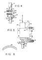
- Figure 3 shows an inverted enlarged view of the male mold 2 containing a cast lens 33.
- Peripheral edge 32 with undesirable flash is removed by the cutting tool generally along line a-a. Slight buffing may be desirable after the cutting operation. Due to the small size and transparent characteristic of the lens, the trimming of the edge portion of the lens is preferably done while the lens is secured within the ring 12 of male mold 2.
- any eccentricity between opening 38 defined in male mold 2 and the outside diameter 40 of mold 2 will result in an asymmetrical trimming of the lens. This could result in unacceptable contact lens for human use.
- the thickness of the peripheral edge of the lens could be about 0.087 mm precision cutting is necessary to trim only a selected portion of the edge.
- Figure 4 shows one embodiment of a cutting device 42 of this invention that can compensate for any eccentricity between the opening 38 in male mold 2 and the outside diameter 40 of male mold 2.
- cutting device 42 includes a housing 44 having secured thereto support member 46 pivotable about pin 48.
- Extended support member 46 is spring biased above pin 48 by means of a set screw 50 coupled to spring 52.
- a stop screw 53 is disposed below pin 48.
- extended support member 46 can only pivot counter clockwise against spring 52.
- an extended guiding edge 54 Disposed at the lower tip of extended support member 46 is an extended guiding edge 54.
- a cutting tool 56 having a cutting edge 58.
- the cutting tool 56 is adjusted such that the distance between the guiding edge 54 and cutting edge 58 will allow the guiding edge 54to ride on wall 60 of male mold 2 and position cutting edge 58 to impart an exact trim to the peripheral edge of cast lens 33 secured on male mold 2.
- male mold 2 placed on a rotatable mandrel 62, the positioning of male mold 2 to cutting device 42 will cause the guiding edge 54 to ride on outer wall 60 of male mold 2 while cutting edge 58 imparts the necessary trimming to the edge of lens 33.
- the support member is spring loaded and has a pivotal point, guiding edge 54 and cutting edge 58 will follow any run-out created by the eccentricity between the outside diameter 40 of male mold 2 and opening 38 defined in male mold 2.
- the trim made on the periphery of lens 33 will be concentric with the outside diameter of the mold and thereby the outside diameter of the lens.
- cutting edge 58 is provided with a sharp segment for trimming the lens.
- Guiding edge 54 can be straight or appropriately curved to conform to the contour of the cylindrical wall of male mold 2 to facilitate sliding thereon and provide greater stability.
- Figure 5 shows another embodiment of a novel cutting device of the invention employing some similar elements which are identified with the same reference numbers.
- a stop screw 64 is disposed above pin 48 and prevents extended support member 46 from pivoting clockwise.
- a conventional spring plunger 66 that biases extended support member 46 against counter clockwise rotation. Thus support member 46 can only be pivoted counter clockwise against the force of spring plunger 66.
- a conventional optical extender 68 coupled to a fiber optic probe 70 is secured above cutting tool 56 and positioned so that light can be directed to the surface of lens 33.
- the fiber optics means (68, 70) is calibrated to deliver a signal when the light reflected from the lens indicates that the lens is properly positioned to be trimmed.
- a selected time period after detecting the signal from the fiber optic means and the stopping of the advancing of the cutting device will insure that the cutting operation has been completed. It is within the scope of this invention to have the signal from the fiber optic means stop the advancing cutting device and then after a preset time generate another signal to automatically remove the cutting device from the lens and position the cutting device adjacent to another mold containing a lens to be trimmed.
- lens 33 is generally buffed and then removed from the mold.
- a lens 33 is shown in Figure 6 after being removed from the mold.
- Figure 7 shows the preferred embodiment of the invention employing some similar elements which are identified with the same reference numbers.
- a stop screw 64 is disposed above pin 48 and prevents extended support member 46 from pivoting clockwise.
- a conventional spring plunger 66 that biases extended support member 46 against counter clockwise rotation. Thus support member 46 can only be pivoted counter clockwise against the force of spring plunger 66.
- a conventional air gage sensing means 72 of the type supplied by Edmunds Manufacturing Company, Farmington Industrial Park, Farmington, Connecticut 06032, is shown as comprising an air regulator 74 coupled to restriction means 76 (for regulating the flow of gas) which in turn is coupled to nozzle 78.
- Nozzle 78 is positioned so that air can be directed to the surface of lens 33.
- the signal from air gage sensing means 72 stop the advancing cutting device and then after a preset time generate another signal to automatically remove the cutting device from the lens and position the cutting device adjacent another mold containing a lens to be trimmed.
- lens 33 is generally buffed and then removed from the mold. A lens 33 is shown in Figure 6 after being removed from the mold.
- the molds are themselves preferably manufactured from thermoplastic materials, for example low density polyethylene or polypropylene. These and other suitable materials are described in U.S. Patents 4,208,365 and 4,121,896.
- the process of the invention is not limited to trimming soft plastic contact lenses, i.e., hydrogels and their hydrated state, although these are preferred articles. Also included for trimming are the hard or rigid contact lenses as well as flexible, hydrophobic truncated contacted lenses.
- novel process results in advantages over prior art methods in that a contact lens is cast directly from the desired lens-forming material and then edge trimmed using the novel device of this invention, polishing of the optical surfaces is not required although only minimum finishing or buffing of the lens edges may be required in some applications.
- the overall manufacturing of finished lenses using the novel cutting device is far less labor intensive than with prior procedures, e.g., lathe procedure. As with most soft lenses, the lens will be washed with water to remove any catalyst residue and unreacted monomer, then equilibrated in aqueous or saline solution to attain their final dimensions.
- the liquid lens-forming mixture can comprise monomer, prepolymer or vulcanizable components.
- Particular suitable components are hydrophilic monomers preferably including those which form slightly or moderately crosslinked, three dimensional networks such as those disclosed in U.S. 3,822,089.
- Illustrative hydrophilic monomers include water soluble monoesters of an acrylic acid or methacrylic acid with an alcohol having an esterifiable hydroxyl group and at least one additional hydroxyl group such as the mono-and polyalkylene glycol monoesters of methacrylic acid and acrylic acid, e.g., ethylene glycol monomethacrylate, ethylene glycol monoacrylate, diethylene glycol monomethacrylate, diethylene glycol monoacrylate, propylene glycol monomethylate, dipropylene glycol monoacrylate, and the like; the N-alkyl and N,N-dialkyl substituted acrylamides and methacrylamides such as N-methylacrylamide, N,N-dimethylacrylamide, N-methylme
- Hydrophilic monomers particularly useful in the practice of the invention to manufacture contact lenses include hydrophobic acrylic esters, suitably lower alkyl acrylic esters, preferably wherein the alkyl moiety contains 1-5 carbon atoms, such as methyl acrylate or methacrylate, ethyl acrylate or methacrylate, n-propyl acrylate or methacrylate, isopropyl acrylate or methacrylate, isobutyl acrylate or methacrylate, n-butyl acrylate or methacrylate, or mixtures thereof.
- hydrophobic acrylic esters suitably lower alkyl acrylic esters, preferably wherein the alkyl moiety contains 1-5 carbon atoms, such as methyl acrylate or methacrylate, ethyl acrylate or methacrylate, n-propyl acrylate or methacrylate, isopropyl acrylate or methacrylate, isobutyl acrylate or methacrylate, n-buty
- Suitable monomers include the ethylenically unsaturated monocarboxylic acid esters, in particular, the methacrylic and acrylic acid esters of siloxane monomers and polymers with/without a pendant hydroxyl group. These monomers are well documented in the contact lens art; see, for example, U.S. Pat. Nos. 4,139,548; 4,235,985; 4,152,508; 3,808,178; 4,139,692; 4,248,989; and 4,139,513.
- the preferred monomeric mixtures are those which contain at least one alkylene glycol monoester of methacrylic acid, especially ethylene glycol monomethacrylate, and at least one crosslinking monomer such as the alkylene glycol diester of methacrylic acid, especially ethylene glycol dimethacrylate.
- Such mixtures may contain other polymerizable monomers, desirably in minor amounts such as N-vinylpyrrolidone, methyl methacrylate, acrylamide, glycidyl methacrylate, N-methylacrylamide, diethylene glycol monomethacrylate, and others illustrated above.
- the above illustrated monomers may be further admixed with a minor proportion of di- or polyfunctional polymerizable species to cause crosslinking of the polymeric matrix as polymerization or curing proceeds.
- di- or polyfunctional species include: divinylbenzene, ethylene glycol diacrylate or methacrylate, propylene glycol diacrylate or methacrylate, and the acrylate or methacrylate esters of the following polyols: triethanolamine, glycerol, pentaerythritol, butylene glycol, diethylene glycol, triethylene glycol, tetraethylene glycol, mannitol, sorbitol and the like.
- Other crosslinking monomers can be illustrated by N,N-methylene-bis-acrylamide or methacrylamide, sulfonated divinylbenzene, and divinylsulfone.
- Additional lens-forming materials which are suitable in the fabrication of contact lenses are illustrated by one or more of the following U.S. Patents: 2,976,576; 3,220,960; 3,937,680; 3,948,871; 3,949,021; 3,983,083; 3,988,274; 4,018,853; 3,875,211; 3,503,942; 3,532,679; 3,621,079; 3,639,524; 3,700,761; 3,721,657; 3,758,448; 3,772,235; 3,786,034; 3,803,093; 3,816,571; 3,940,207; 3,431,046; 3,542,461; 4,055,378; 4,064,086; and 4,062,627.
- the polymerization reaction can be carried out in bulk or with an inert solvent.
- suitable solvents include water; organic solvents such as watersoluble lower aliphatic monohydric alcohols as well as polyhydric alcohols, e.g., glycol, glycerol, dioxane, etc.; and mixtures thereof.
- the solvent comprises a minor amount of the reaction medium, i.e., less than about 50 weight percent.
- Polymerization of the lens-forming mixture may be carried out with free radical catalysts and/ or initiators of the type in common use in vinyl polymerization.
- catalyst species can include the organic peroxides, the alkyl percarbonates, hydrogen peroxides, and inorganic materials such as ammonium, sodium, or potassium persulfate.
- Polymerization temperatures can vary from about 20°C, and lower, to about 100°C, and higher.
- Polymerization of the monomer or prepolymer material can also be effected using, for example, radiation (U.V., X-ray, microwave, or other well-known forms of radiation) with/without the presence of well-known initiator(s) and/or catalyst(s).
- radiation U.V., X-ray, microwave, or other well-known forms of radiation
- Both anterior and posterior surfaces of the lenses may consist of entirely spherical curves or aspherical curves or combinations of both.
- the central position of the lens may consist of spherical curves on both the anterior and posterior surface, and the periphery of the anterior surface may consist of a steeper or flatter spherical curve, and the periphery of the posterior surface may be aspheric to achieve improved fitting characteristics.
- one or both of the surfaces may be toric in the central or optical zone; however, the peripheral portion must be symmetrical with respect to the central axis of the lens to achieve proper seating or mating of the integral rim.
- Female high density polyethylene molds were prepared by injection molding on a convex male steel mold having an outside diameter of 12.0 mm, a central radius of curvature of 7.50 mm with a chord diameter of 10.0 mm and a peripheral radium of curvature of 7.00 mm.
- Male high density polyethylene molds were prepared by injection molding in a concave steel mold having an inside diameter of 11.9 mm, central radius of 7.00 mm with a chord diameter of 11.0 mm, and a peripheral curve having a radius of 12.5 mm.
- the periphery of the curved mold surface was recessed to provide a periphery rim 0.01 mm wide at the apex extending 0.12 mm from the edge of the curve.
- Radiuscope measurement showed the central radius of curvature of the female concave molds was 11.8 mm, and the central radius of curvature was 6.95 ⁇ 0.03 mm.
- a concave female mold was placed on a flat surface with the cavity projecting upward.
- a solution consisting of carefully purified 2-hydroxyethyl methacrylate, 100 parts; distilled water, 30 parts; ethylene glycol dimethyl ether, 25 parts; triethylene glycol dimethacrylate, 0.4 parts; an diisopropyl percarbonate, 0.2 parts; was prepared by thorough mixing.
- One-half ml. of the solution was placed in the female mold, and the male mold half was slowly inserted to displace excess solution and to displace any bubbles. Slight pressure was applied on the male half to ensure seating of the rim.
- the filled mold was then placed in a circulating air oven at 45°C for 1 1/2 hours. After cooling to room temperature, the mold was opened, the "ring" of polymerized material filling the cylindrical void in the annulus between the mold halves was removed, and the flexible lens adhered lightly to the male half of the mold.
- the male mold containing the formed lens secured within the circumferential rim was inverted and placed on a rotatable mandrel.
- a cutting device as basically shown in Figure 4 was positioned adjacent to the revolving mandrel and the guiding edge was positioned to contact the cylindrical wall of the mold. This insured that the cutting edge was precisely positioned to trim a selected area of undesirable flash at the peripheral edge of the lens as basically shown in Figure 3.
- the finished contact lens - was placed in a physiological solution.
- the lens had an optical power of -3 diopters.
- the lens had a center thickness of 0.04 mm and an edge thickness of 0.09 mm.
- the edge of the lens was reduced in thickness by 0.04 mm thereby providing a tapered edge portion for the lens without sharp points that could irritate the eye of the user.
Description
- The present invention relates to a cutting device for precision trimming a selected portion of the peripheral edge of a cast contact lens secured within a flexible circumferential rim on the exter- . nal surfaces of a male mold. The invention also relates to a method for the economical and precision trimming of a selected portion of the peripheral edge of a cast contact lens secured within a circumferential rim on the external surface of a male mold.
- US-A-3295417 discloses an apparatus for cutting optical elements such as lenses for sunglasses. Such an apparatus cannot be used for trimming the edge of contact lenses, said trimming presenting problems unlike those which exist for conventional glass lenses which are to be mounted on a frame.
- A widely practiced technique for the manufacture of soft contact lenses involves the lathing procedure (DE-A 2102820). This technique has many drawbacks inasmuch as it is a labor intensive operation, requires several steps, is relatively expensive, and the finished lens product is characterized by striations on its optical surfaces. In the lathing technique, an appropriate polymerization medium is first polymerized into a cylindrical shape from which there are cut so-calldd-lens "buttons" or lens blanks, or the lens blanks perse can be made in appropriate molds. The blanks are subjected to a postcure treatment to improve certain of their physical characteristics. A pre- determined curved surface is thereafter cut on one face of the blank by using precision lathe machinery and the cut curved surface is polished to an optical surface. Formation of an optical surface on the opposite face of the blank requires adhering the partially cut blank to an arbor or mandrel by means of a waxy substance in a manner that the uncut face of the blank is exposed for the lathing and polishing operations. Thereafter, there are washing and cleaning steps to remove residues from the cutting and polishing procedures and eventually, as with soft contact lenses, soaking in a physiologic solution until osmotic equilibrium is reached at which stage the hydrogel lens attains its final dimensions. This method suffers from the disadvantage of requiring highly skilled artisans for quality production.
- In utilizing closed mold system for casting contact lenses, the inevitable shrinkage that occurs on polymerization can result in surface and/or edge irregularity of the cast lenses. With some monomeric materials, the volumetric shrinkage during polymerization can be as high as 22%. This degree of shrinkage will generally prevent satisfactory casting of soft contact lenses where surface finish and sharpe are important. For example, as taught in U.S. Patent No. 3,660,545, a polymerizable acrylate, or methacrylate ester mixture held in a closed glass mold invariably would pull away from at least one mold surface and cause the formation of surface voids which render the cast lines unsuitable for use as a contact lens for humans.
- A closed mold casting system in which the disadvantage associated with shrinkage of the polymerizable or curable material has been proposed in U.S. Patent No. 4,121,896 to T. H. Shepherd. According to the process described in this United States Patent, complementing replica male and female mold members each having an optical molding surface are prepared by injection molding of plastic composition in the master mold pairs. The plastic mold members are then longitudinally aligned and used to mold contact lenses, one of the molding surfaces being provided with a flexible circumferential rim which defines the periphery of the resulting lens. The lens-forming polymerizable or curable material which will constitute the lens is charged into the female mold member or portion. The complementing male member or portion is brought into contact with the female mold member so that the flexible rim portion is seated on the opposite molding surface. During molding the lens-forming material contracts causing the flexible rim to flex, inwardly usually, whereby the two mold members move towards each other. Once the molding cycle is completed the mold members are separated and the resulting contact lens is secured within the circumferential rim on the mold. The lens can then be removed in a condition ready for use, except for cleaning and perhaps a buffing of the lens edge.
- Although the above-described closed mold casting process does produce precision lenses, time-consuming steps must be taken to often- times remove undesirable flash on the peripheral edge of the lenses as by buffing in order to make them commercially acceptable. If a male mold containing the lens is positioned on a revolving mandrel and a conventional cutting tool is employed to trim a selected peripherial edge portion of the lens, then due to the possibility of eccentricity between the opening in the cylindrical mold and the outer diameter of the mold, an asymmetrical trim could be imparted to the lens. This could result in unacceptably soft contact lenses being produced.
- Accordingly, one or more objects will be achieved by the practice of the invention.
- Objects of the invention are for the provision of novel cutting devices and novel methods for symmetrically trimming the peripheral edge portion of a cast lens.
- Another object of the invention is to provide a novel cutting device employing guiding means associated with cutting means for the precision trimming of a selected portion of the peripheral edge of a soft contact lens.
- Yet another object of the invention is to provide a novel cutting device employing guiding means associated with cutting means and utilizing fiber optic means for detecting when the selected portion of the peripheral edge of a cast soft contact lens is in position to be trimmed.
- Another additional object of the invention is to provide a novel cutting device employing guiding means associated with cutting means and utilizing air gage sensing means for detecting when the selected portion of the peripheral edge of a cast soft contact lens is in position to be trimmed.
- Still another object of the invention is to provide a method for the precision trimming of a selected portion of the peripheral edge of a cast soft contact lens which is not labor intensive or capital intensive, which can be operated in an efficient manner on a continuous basis, which is relatively small in size as to be readily portable and/or obviates various disadvantages of the art.
- The foregoing as well as additional objects will become fully apparent from the following description and the accompanying drawings.
- The invention relates to a cutting device for trimming a selected peripheral edge portion of a contact lens secured in a male mold, which cutting device comprises a housing having an extended support member; a cutting means having a cutting edge and said cutting means secured to said support member; said support member having a guiding edge disposed a fixed distance from said cutting edge; and said guiding edge and said cutting edge being cooperatively associated so that when said guiding edge contacts the outer wall of a male mold, the cutting edge will be positioned for the precision trimming of an edge portion of a contact lens secured on the male mold.
- Through the cooperative association of the guiding edge of the support member and the cutting edge of the cutting means, a symmetrical and precision trimming of a selected portion of the peripheral edge of a contact lens secured on a male mold can be performed. Specifically, when the guiding edge is positioned to contact the outer wall of a cylindrical male mold containing a cast contact lens, the cutting edge will be precisely positioned for trimming a preselected portion of the peripheral edge of a contact lens secured on the male mold. Thus as the male mold containing the contact lens is rotated on a conventional mandrel, the guiding edge will ride on the outer wall of the male mold thereby insuring that the cutting edge is positioned for selectively trimming a precise segment of the edge of the contact lens. This guiding edge and cutting edge arrangement will compensate for any eccentricity that may exist between the opening defined in the male mold which is adapted to receive a conventional rotating mandrel and the outer diameter of the male mold. Through the use of the guiding edge on the extended support member which slides on the outer wall of the male mold, the cutting edge will impart a precision trim to the peripheral edge portion of the contact lens such that the cut of the lens is concentric with the outer diameter of the lens and independent of any eccentricity that may exist between the opening defined in the mold and the outer diameter of the mold.
- Preferably, the extended support member should be pivotable with respect to the housing of the device so that the housing could remain fixed while the extended support member and cutting means secured thereon would be free to follow any run-out created by any eccentricity between the outer diameter of the male mold and the hole defined in the center of the male mold. Another preferred feature of the invention is to have the cutting means adjustably mounted on the support member so that the distance between the cutting edge and the guiding edge can be adjusted to accommodate different size molds. In addition, the cutting means should be easily disassembled from the cutting device to facilitate the sharpening of the cutting edge when desired or to replace the cutting edge when necessary.
- In another embodiment of the invention the cutting edge comprises a sharp segment and a blunt segment such that the sharp segment could be positioned to precision trim the contact lens while the blunt segment could be positioned to slide upon the circumferential rim of the male mold that secures the contact lens to the mold. When using male molds, the guiding edge of the support member could be appropriately curved to conform to the contour of the wall of the mold so as to facilitate the sliding of the guiding edge on the mold.
- An additional embodiment of the invention would entail the use of fiber optics means or air gage sensing means in the novel cutting device to detect when the cutting edge is properly distanced from the contact lens so that the extremely accurate trimming of the lens edge can be accomplished. Since the male mold will be rotating at the same speed as the mandrel, the detection of the precise position that trimming of the lens will occur by the fiber optic means or air gage sensing means will provide a signal which will cause the advancing cutting device to stop whereupon the lens trimming operation will be accomplished. The male mold can be taken off the mandrel and the contact lens can then be removed in a condition ready for use, except for cleaning and perhaps a buffing of the lens edge. Due to the small size of contact lenses and specifically to the extremely small size of the edge portion of the lens to be trimmed, it is rather difficult to determine when and if trimming has been completed.
- Advantageously by utilizing the use of fiber optic means of air gage sensing means as described above, the cutting device can be used on a continuous operation to produce contact lenses to exact physical specifications in a minimum of time since the fiber optic means or air gage sensing means will insure when the trimming of the lens has commenced.
- Conventional fiber optic means can be used in conjunction with the novel cutting device of this invention. Generally, the distal end of a fiber bundle (for example, from an optical extender coupled to a fiber optic probe) is placed in close proxomity to where the reflected surface of the lens in the male mold would be positioned to be trimmed by the cutting edge of the cutting means. Light traveling down the fiber bundle is reflected from the contact lens surface back onto receive fibers of the bundle located in a conventional probe tip and such reflection is detected by a photo sensor. The amount of reflected light is related to the distance between the face of the fibers and the reflected surface, the acceptance angle, or numerical aperture of the fibers, and the reflectivity of the surface. Accordingly, the fiber optic means can be used as a convenient prox- imitor for generating a signal to stop the advancing cutting device when the contact lens surface is precisely positioned for trimming by the cutting edge of the cutting means. A signal can be generated to automatically remove the cutting device to another rotating male mold on a mandrel thus providing a continuous operation for trimming the edge of cast lenses.
- Conventional air gage sensing means can be used in conjunction with the novel cutting device of this invention. Commercial air gage sensing means can be obtained from Edmunds Manufacturing Company, Farmington Industrial Park, Farmington, Connecticut 06032. Generally, air from a regulated supply will flow through a restriction device coupled to an output nozzle. When an object is placed in front of the nozzle and slowly brought towards of the nozzle, the air flow will be restricted and pressure down stream of the restriction device will gradually build up until it is the same as the regulated supply. The exact distance of the object from the end of the nozzle can be detected by measuring the change of air flow and the change of pressure. A summary of air gage sensing means is disclosed in a publication titled Gage Page by Edmunds Manufacturing Company, Farmington Industrial Park, Farmington, Connecticut 06032, and the disclosure made therein is fully incorporated herein by reference as if set out in full text. Accordingly, the air gage sensing means can be used as a convenient proximeter for generating a signal to stop the advancing cutting device when the lens surface is precisely positioned for trimming by the cutting edge of the cutting means. This sensing means can also be used to provide an automatic system for trimming the edge of cast lenses.
- Another aspect of the invention is directed to a method for trimming a selected peripheral edge portion of a contact lens mounted on a male mold comprising the steps:
- (a) placing a male mold such as a cylindrical or tapered mold, containing an exposed cast contact lens secured on one end of the mold on a rotatable mandrel;
- (b) positioning a cutting edge of a cutting tool adjacent a guiding edge of a support member such that the cutting edge is positioned a pre- determined distance from the guiding edge; and
- (c) rotating the mandrel containing the male mold with the contact lens and contacting the guiding edge of the support member to the revolving outer wall of the male mold thereby positioning the cutting edge against the peripheral edge of the contact lens for the precision trimming of a selected edge portion of the contact lens secured on the male mold.
- The above method can be modified by employing fiber optic means for detecting when the contact lens is positioned for trimming by the cutting means and then removing the male mold from the cutting means after a predetermined fixed time that would insure that the lens had been completely trimmed. By coupling the fiber optic means to appropriate power operated machinery, a fixed time period after a signal is detected from the fiber optic means, the male mold could be automatically removed from the cutting means and replaced by another male mold containing a contact lens to be trimmed. The male molds can be arranged in a carousel type arrangement and thus be advanced and removed from the cutting means on a continuous basis.
- The present invention will become more apparent from the following description thereof when considered together with the accompanying drawing which is set forth as being exemplary of embodiments of the present invention and is not intended in any way to limited thereof and wherein:
- Figure 1 is a side elevation in cross section of a convex male molding surface with a flexible rim attached thereto and a concave female molding surface.
- Figure 2 is a side elevation in cross section illustrating a mating of the molds of Figure 1 and wherein the rim is shown in flexed form.
- Figure 3 is an enlarged side elevation in cross section of the male mold of Figure 2 shown inverted.
- Figure 4 is a side elevation partly in cross section of the novel cutting device of this invention.
- Figure 5 is a side elevation partly in cross section of another embodiment of the invention which comprises the novel cutting device which includes a fiber optic sensing device.
- Figure 6 is a side elevation in cross section of a cast contact lens that was trimmed by the cutting device of this invention.
- Figure 7 is a side elevation partly in cross section of another embodiment of the invention which comprises the novel cutting device which includes an air gage sensing means.
- The mold comprises two portions, namely a
male portion 2 and afemale portion 4. Themale mold 2 comprises a substantially cylindrical support segment 6 having, optionally, attached to the upper end thereof arim 8. Cylindrical support segment 6 defines an opening which is adapted to fit over a mandrel as will be discussed later. Cylindrical support segment 6 is closed bymale molding surface 10 circumferentially attached to the bottom of cylindrical support segment 6. The curvature ofmale molding surface 10 is predetermined to comply with the optical requirements of the lens to be produced. The curvature may be entirely spherical or aspherical or combinations of both.Male molding surface 10 can be toric in the central or optical zone; however, the peripheral portion must be symmetrical with respect to the central axis of the lens in order to achieve proper seating or mating withrim 8. As shown in Figure 1, a flexiblecircumferential ring 12 is located aroundmale molding surface 10 and is integral therewith.Ring 12 comprises anouter surface 14, aninner surface 16 and acontact edge 18. - The
female mold 4 includes acylindrical support member 22 set, optionally, in a base 24 set circumferentially thereto and afemale molding surface 26 set internally incylindrical support member 22. As with respect tomale molding surface 10 the curvature offemale molding surface 26 is pre-determined and may vary in the same manner as the curvature ofmold surface 10. The only limitation placed upon the mutual relationship of curvature ofmale molding surface 10 andfemale molding surface 26 is that the article to be molded therebetween shall have the general characteristics suitable for a contact lens, namely that the article produced thereby shall have a concave surface which will contact, when in use, the eyeball of the user and a second, convex surface, which shall contact the internal portion of the eyelid of the user. - During the operation of the process, a polymerizable or
curable material 30 which will constitute the contact lens is placed onfemale molding surface 26 offemale mold 4. Themale mold 2 is positioned into thefemale mold 4 in such a manner that contactedge 18 of flexiblecircumferential ring 12 in this case attached circumferentially around themale molding surface 10 just touchesfemale molding surface 26 as shown in Figure 2. At this pointexcess molding material 31 is squeezed out between the outer edge of support segment 6 ofmale mold 2 and theinner support wall 28 offemale mold 4. In the embodiment shown in the Figures 1 and 2, no runoff channels are shown or provided. Nevertheless, the provisions of molds having such channels can be used. They are sometimes not utilized since the provision of such molds required an additional, and more expensive, step in manufacturing the molds and this provision has not been found to be needed in most applications. - The drawings herein are not to scale, in particular, with regard to the flexible
circumferential ring 12 and the clearance betweenmale mold 2 andfemale mold 4. - The mold assembly containing the molding material is then subjected to the molding processes. During the molding stage, the polymerizable or curable molding material will contract as much as 20% of the volume of the molding material originally present between
surfaces male molds 2 . andfemale mold 4 to move towards each other. The flexibility ofring 12 permits the molds to thus approach each other more closely due to the flexing ofring 12 in a uniform manner. If desired, external pressure can be applied to ensure that the molding surfaces do approach each other as closely as possible. However, the application of such external pressure is optional and, while in certain cases, may give rise to improved results, the operation of the process will proceed without said external pressure under appropriate activity conditions. Upon completion of the molding step, the molds are separated. Figure 3 shows an inverted enlarged view of themale mold 2 containing acast lens 33.Peripheral edge 32 with undesirable flash is removed by the cutting tool generally along line a-a. Slight buffing may be desirable after the cutting operation. Due to the small size and transparent characteristic of the lens, the trimming of the edge portion of the lens is preferably done while the lens is secured within thering 12 ofmale mold 2. However, whenmale mold 2 is placed on a conventional mandrel 36 (shown in outline form in Figure 3) and a conventional cutting tool is used to trim the edge, any eccentricity betweenopening 38 defined inmale mold 2 and theoutside diameter 40 ofmold 2 will result in an asymmetrical trimming of the lens. This could result in unacceptable contact lens for human use. Generally, since the thickness of the peripheral edge of the lens could be about 0.087 mm precision cutting is necessary to trim only a selected portion of the edge. - Figure 4 shows one embodiment of a
cutting device 42 of this invention that can compensate for any eccentricity between the opening 38 inmale mold 2 and theoutside diameter 40 ofmale mold 2. Specifically, cuttingdevice 42 includes ahousing 44 having secured thereto supportmember 46 pivotable aboutpin 48.Extended support member 46 is spring biased abovepin 48 by means of aset screw 50 coupled tospring 52. To preventextended support member 46 from pivoting aboutpin 48 due tospring 52, a stop screw 53 is disposed belowpin 48. Thus extendedsupport member 46 can only pivot counter clockwise againstspring 52. - Disposed at the lower tip of
extended support member 46 is anextended guiding edge 54. Adjustably secured above guidingedge 54 is acutting tool 56 having a cuttingedge 58. The cuttingtool 56 is adjusted such that the distance between the guidingedge 54 and cuttingedge 58 will allow the guiding edge 54to ride onwall 60 ofmale mold 2 andposition cutting edge 58 to impart an exact trim to the peripheral edge ofcast lens 33 secured onmale mold 2. Withmale mold 2 placed on arotatable mandrel 62, the positioning ofmale mold 2 to cuttingdevice 42 will cause the guidingedge 54 to ride onouter wall 60 ofmale mold 2 while cuttingedge 58 imparts the necessary trimming to the edge oflens 33. Since the support member is spring loaded and has a pivotal point, guidingedge 54 and cuttingedge 58 will follow any run-out created by the eccentricity between theoutside diameter 40 ofmale mold 2 andopening 38 defined inmale mold 2. Thus the trim made on the periphery oflens 33 will be concentric with the outside diameter of the mold and thereby the outside diameter of the lens. - Although not shown, cutting
edge 58 is provided with a sharp segment for trimming the lens. Guidingedge 54 can be straight or appropriately curved to conform to the contour of the cylindrical wall ofmale mold 2 to facilitate sliding thereon and provide greater stability. - Figure 5 shows another embodiment of a novel cutting device of the invention employing some similar elements which are identified with the same reference numbers. As shown, a
stop screw 64 is disposed abovepin 48 and preventsextended support member 46 from pivoting clockwise. Belowpin 48 is aconventional spring plunger 66 that biases extendedsupport member 46 against counter clockwise rotation. Thussupport member 46 can only be pivoted counter clockwise against the force ofspring plunger 66. In this embodiment, a conventionaloptical extender 68 coupled to afiber optic probe 70 is secured above cuttingtool 56 and positioned so that light can be directed to the surface oflens 33. Knowing the exact position wheremale mold 2 should be for precise trimming of the lens, the fiber optics means (68, 70) is calibrated to deliver a signal when the light reflected from the lens indicates that the lens is properly positioned to be trimmed. Withmale mold 2 revolving onrotatable mandrel 62, a selected time period after detecting the signal from the fiber optic means and the stopping of the advancing of the cutting device, will insure that the cutting operation has been completed. It is within the scope of this invention to have the signal from the fiber optic means stop the advancing cutting device and then after a preset time generate another signal to automatically remove the cutting device from the lens and position the cutting device adjacent to another mold containing a lens to be trimmed. - After trimming is completed,
lens 33 is generally buffed and then removed from the mold. Alens 33 is shown in Figure 6 after being removed from the mold. - Figure 7 shows the preferred embodiment of the invention employing some similar elements which are identified with the same reference numbers. As shown, a
stop screw 64 is disposed abovepin 48 and preventsextended support member 46 from pivoting clockwise. Belowpin 48 is aconventional spring plunger 66 that biases extendedsupport member 46 against counter clockwise rotation. Thussupport member 46 can only be pivoted counter clockwise against the force ofspring plunger 66. In this embodiment, a conventional air gage sensing means 72, of the type supplied by Edmunds Manufacturing Company, Farmington Industrial Park, Farmington, Connecticut 06032, is shown as comprising anair regulator 74 coupled to restriction means 76 (for regulating the flow of gas) which in turn is coupled tonozzle 78.Nozzle 78 is positioned so that air can be directed to the surface oflens 33. Using conventional means to measure the change of air flow and change of pressure in air gage sensing means 72 due to the placement oflens 33 in front ofnozzle 78, the precise location oflens 33 from the nozzle can be determined. Oncelens 33 is precisely positioned to be trimmed by the cutting device a signal can be generated to stop the advancement of the cutting device. Withmale mold 2 revolving onrotatable mandrel 62, a selected time period after detecting the signal from air gage sensing means 72, which indicates that the lens is in position to be trimmed, will insure that the cutting operation has been completed. It is within the scope of this invention to have the signal from air gage sensing means 72 stop the advancing cutting device and then after a preset time generate another signal to automatically remove the cutting device from the lens and position the cutting device adjacent another mold containing a lens to be trimmed. As stated above, after trimming is completed,lens 33 is generally buffed and then removed from the mold. Alens 33 is shown in Figure 6 after being removed from the mold. - The molds are themselves preferably manufactured from thermoplastic materials, for example low density polyethylene or polypropylene. These and other suitable materials are described in U.S. Patents 4,208,365 and 4,121,896.
- The process of the invention is not limited to trimming soft plastic contact lenses, i.e., hydrogels and their hydrated state, although these are preferred articles. Also included for trimming are the hard or rigid contact lenses as well as flexible, hydrophobic truncated contacted lenses.
- The novel process results in advantages over prior art methods in that a contact lens is cast directly from the desired lens-forming material and then edge trimmed using the novel device of this invention, polishing of the optical surfaces is not required although only minimum finishing or buffing of the lens edges may be required in some applications. The overall manufacturing of finished lenses using the novel cutting device is far less labor intensive than with prior procedures, e.g., lathe procedure. As with most soft lenses, the lens will be washed with water to remove any catalyst residue and unreacted monomer, then equilibrated in aqueous or saline solution to attain their final dimensions.
- The liquid lens-forming mixture can comprise monomer, prepolymer or vulcanizable components. Particular suitable components are hydrophilic monomers preferably including those which form slightly or moderately crosslinked, three dimensional networks such as those disclosed in U.S. 3,822,089. Illustrative hydrophilic monomers include water soluble monoesters of an acrylic acid or methacrylic acid with an alcohol having an esterifiable hydroxyl group and at least one additional hydroxyl group such as the mono-and polyalkylene glycol monoesters of methacrylic acid and acrylic acid, e.g., ethylene glycol monomethacrylate, ethylene glycol monoacrylate, diethylene glycol monomethacrylate, diethylene glycol monoacrylate, propylene glycol monomethylate, dipropylene glycol monoacrylate, and the like; the N-alkyl and N,N-dialkyl substituted acrylamides and methacrylamides such as N-methylacrylamide, N,N-dimethylacrylamide, N-methylmethacrylamide, N,N-dimethylmethacrylamide, and the like; N-vinylpyrrolidone; the alkyl substituted N-vinyl pyrrolidones, e.g., methyl substituted N-vinylpyrrolidone; glycidyl methacrylate; glycidyl acrylate; the unsaturated amines; the alkyl ethyl acrylates; solubilized collagen; mixtures thereof; and others known to the art.
- Hydrophilic monomers particularly useful in the practice of the invention to manufacture contact lenses include hydrophobic acrylic esters, suitably lower alkyl acrylic esters, preferably wherein the alkyl moiety contains 1-5 carbon atoms, such as methyl acrylate or methacrylate, ethyl acrylate or methacrylate, n-propyl acrylate or methacrylate, isopropyl acrylate or methacrylate, isobutyl acrylate or methacrylate, n-butyl acrylate or methacrylate, or mixtures thereof.
- Other suitable monomers include the ethylenically unsaturated monocarboxylic acid esters, in particular, the methacrylic and acrylic acid esters of siloxane monomers and polymers with/without a pendant hydroxyl group. These monomers are well documented in the contact lens art; see, for example, U.S. Pat. Nos. 4,139,548; 4,235,985; 4,152,508; 3,808,178; 4,139,692; 4,248,989; and 4,139,513.
- Among the preferred monomeric mixtures are those which contain at least one alkylene glycol monoester of methacrylic acid, especially ethylene glycol monomethacrylate, and at least one crosslinking monomer such as the alkylene glycol diester of methacrylic acid, especially ethylene glycol dimethacrylate. Such mixtures may contain other polymerizable monomers, desirably in minor amounts such as N-vinylpyrrolidone, methyl methacrylate, acrylamide, glycidyl methacrylate, N-methylacrylamide, diethylene glycol monomethacrylate, and others illustrated above.
- The above illustrated monomers, monomeric mixtures including mixtures of hydrophobic and hydrophilic reactants, may be further admixed with a minor proportion of di- or polyfunctional polymerizable species to cause crosslinking of the polymeric matrix as polymerization or curing proceeds. Examples of such di- or polyfunctional species include: divinylbenzene, ethylene glycol diacrylate or methacrylate, propylene glycol diacrylate or methacrylate, and the acrylate or methacrylate esters of the following polyols: triethanolamine, glycerol, pentaerythritol, butylene glycol, diethylene glycol, triethylene glycol, tetraethylene glycol, mannitol, sorbitol and the like. Other crosslinking monomers can be illustrated by N,N-methylene-bis-acrylamide or methacrylamide, sulfonated divinylbenzene, and divinylsulfone.
- Additional lens-forming materials which are suitable in the fabrication of contact lenses are illustrated by one or more of the following U.S. Patents: 2,976,576; 3,220,960; 3,937,680; 3,948,871; 3,949,021; 3,983,083; 3,988,274; 4,018,853; 3,875,211; 3,503,942; 3,532,679; 3,621,079; 3,639,524; 3,700,761; 3,721,657; 3,758,448; 3,772,235; 3,786,034; 3,803,093; 3,816,571; 3,940,207; 3,431,046; 3,542,461; 4,055,378; 4,064,086; and 4,062,627.
- The polymerization reaction can be carried out in bulk or with an inert solvent. Suitable solvents include water; organic solvents such as watersoluble lower aliphatic monohydric alcohols as well as polyhydric alcohols, e.g., glycol, glycerol, dioxane, etc.; and mixtures thereof. In general, the solvent comprises a minor amount of the reaction medium, i.e., less than about 50 weight percent.
- Polymerization of the lens-forming mixture may be carried out with free radical catalysts and/ or initiators of the type in common use in vinyl polymerization. Such catalyst species can include the organic peroxides, the alkyl percarbonates, hydrogen peroxides, and inorganic materials such as ammonium, sodium, or potassium persulfate. Polymerization temperatures can vary from about 20°C, and lower, to about 100°C, and higher.
- Polymerization of the monomer or prepolymer material can also be effected using, for example, radiation (U.V., X-ray, microwave, or other well-known forms of radiation) with/without the presence of well-known initiator(s) and/or catalyst(s).
- A procedure for the making of molds and formation of lenses suitable for use with the cutting device of this invention is described in U.S. Patent 4,121,896. As disclosed in this reference, the design of lenses by the cast system employing a mold with a circumferential rim is not restricted to any particular set of parameters. Both anterior and posterior surfaces of the lenses may consist of entirely spherical curves or aspherical curves or combinations of both. For example, the central position of the lens may consist of spherical curves on both the anterior and posterior surface, and the periphery of the anterior surface may consist of a steeper or flatter spherical curve, and the periphery of the posterior surface may be aspheric to achieve improved fitting characteristics.
- In addition, one or both of the surfaces may be toric in the central or optical zone; however, the peripheral portion must be symmetrical with respect to the central axis of the lens to achieve proper seating or mating of the integral rim.
- Female high density polyethylene molds were prepared by injection molding on a convex male steel mold having an outside diameter of 12.0 mm, a central radius of curvature of 7.50 mm with a chord diameter of 10.0 mm and a peripheral radium of curvature of 7.00 mm. Male high density polyethylene molds were prepared by injection molding in a concave steel mold having an inside diameter of 11.9 mm, central radius of 7.00 mm with a chord diameter of 11.0 mm, and a peripheral curve having a radius of 12.5 mm. The periphery of the curved mold surface was recessed to provide a periphery rim 0.01 mm wide at the apex extending 0.12 mm from the edge of the curve. Radiuscope measurement showed the central radius of curvature of the female concave molds was 11.8 mm, and the central radius of curvature was 6.95±0.03 mm.
- A concave female mold was placed on a flat surface with the cavity projecting upward. A solution consisting of carefully purified 2-hydroxyethyl methacrylate, 100 parts; distilled water, 30 parts; ethylene glycol dimethyl ether, 25 parts; triethylene glycol dimethacrylate, 0.4 parts; an diisopropyl percarbonate, 0.2 parts; was prepared by thorough mixing. One-half ml. of the solution was placed in the female mold, and the male mold half was slowly inserted to displace excess solution and to displace any bubbles. Slight pressure was applied on the male half to ensure seating of the rim. The filled mold was then placed in a circulating air oven at 45°C for 1 1/2 hours. After cooling to room temperature, the mold was opened, the "ring" of polymerized material filling the cylindrical void in the annulus between the mold halves was removed, and the flexible lens adhered lightly to the male half of the mold.
- The male mold containing the formed lens secured within the circumferential rim was inverted and placed on a rotatable mandrel. A cutting device as basically shown in Figure 4 was positioned adjacent to the revolving mandrel and the guiding edge was positioned to contact the cylindrical wall of the mold. This insured that the cutting edge was precisely positioned to trim a selected area of undesirable flash at the peripheral edge of the lens as basically shown in Figure 3. After the trimming and buffing operations were completed, the lens was easily removed from the mold. The finished contact lens -was placed in a physiological solution. As measured on a Nikon Vertexometer, the lens had an optical power of -3 diopters. The lens had a center thickness of 0.04 mm and an edge thickness of 0.09 mm. Using the novel cutting device of this invention, the edge of the lens was reduced in thickness by 0.04 mm thereby providing a tapered edge portion for the lens without sharp points that could irritate the eye of the user.
Claims (10)
Applications Claiming Priority (2)
| Application Number | Priority Date | Filing Date | Title |
|---|---|---|---|
| US06/533,478 US4647261A (en) | 1983-09-19 | 1983-09-19 | Cutting device and method for the precision trimming of the edge of a cast lens |
| US533478 | 1983-09-19 |
Publications (3)
| Publication Number | Publication Date |
|---|---|
| EP0145516A2 EP0145516A2 (en) | 1985-06-19 |
| EP0145516A3 EP0145516A3 (en) | 1985-07-10 |
| EP0145516B1 true EP0145516B1 (en) | 1988-05-04 |
Family
ID=24126124
Family Applications (1)
| Application Number | Title | Priority Date | Filing Date |
|---|---|---|---|
| EP84401827A Expired EP0145516B1 (en) | 1983-09-19 | 1984-09-14 | Cutting device and method for the precision trimming of the edge of a cast contact lens |
Country Status (7)
| Country | Link |
|---|---|
| US (1) | US4647261A (en) |
| EP (1) | EP0145516B1 (en) |
| JP (1) | JPS60114401A (en) |
| AU (1) | AU568874B2 (en) |
| CA (1) | CA1227125A (en) |
| DE (1) | DE3470865D1 (en) |
| ES (1) | ES535850A0 (en) |
Families Citing this family (11)
| Publication number | Priority date | Publication date | Assignee | Title |
|---|---|---|---|---|
| US5137441A (en) * | 1990-10-30 | 1992-08-11 | Minnesota Mining And Manufacturing Company | Mold assembly for making an ocular lens blank |
| US5110278A (en) * | 1990-11-30 | 1992-05-05 | Pilkington Visioncare, Inc. | Injection molding apparatus for producing a toric lens casting mold arbor |
| JPH0639697A (en) * | 1992-04-14 | 1994-02-15 | Wernicke & Co Gmbh | Processing machine for eyeglass lens edge |
| US5378412A (en) * | 1992-12-02 | 1995-01-03 | Bausch & Lomb Incorporated | Method of edging a contact lens or lens blank |
| JPH0966401A (en) * | 1995-06-21 | 1997-03-11 | Canon Inc | Cylindrical member and manufacture method and device thereof |
| JPH1076415A (en) * | 1996-09-03 | 1998-03-24 | Fuji Photo Optical Co Ltd | Periphery working device for molded optical part |
| US7433027B2 (en) * | 2004-12-22 | 2008-10-07 | Novartis Ag | Apparatus and method for detecting lens thickness |
| US9057595B2 (en) | 2011-11-30 | 2015-06-16 | Novartis Ag | Combination of mirror images to improve signal quality for contact lenses |
| NL2009432C2 (en) * | 2012-09-07 | 2014-03-10 | Innovalens B V | METHOD FOR MANUFACTURING A SEMI-MANUFACTURE INTENDED FOR FORMING A SHTHALMIC DEVICE |
| US9457522B2 (en) | 2013-02-26 | 2016-10-04 | Coopervision International Holding Company, Lp | Methods and apparatus useful in manufacturing lenses |
| CN109676977A (en) * | 2018-12-06 | 2019-04-26 | 杭州索凯实业有限公司 | A kind of car light part optical surface processing technology |
Family Cites Families (29)
| Publication number | Priority date | Publication date | Assignee | Title |
|---|---|---|---|---|
| US2369318A (en) * | 1943-03-27 | 1945-02-13 | Western Electric Co | Apparatus for forming metallic articles |
| US2625061A (en) * | 1949-04-11 | 1953-01-13 | Greenlee Bros & Co | Work position responsive control mechanism |
| US2661640A (en) * | 1950-09-22 | 1953-12-08 | Armag Spezialwerkzeuge Und Mas | Device for shape-turning and for the production of hollow shapes and turned parts bymeans of a rotating cutting tool on machine tools |
| US3301105A (en) * | 1965-02-23 | 1967-01-31 | Quality Optics Inc | Method and apparatus for shaping the edge on a contact lens |
| US3295417A (en) * | 1965-10-07 | 1967-01-03 | Polaroid Corp | Apparatus for cutting optical elements |
| US3514908A (en) * | 1967-11-29 | 1970-06-02 | Bausch & Lomb | Process for finishing contact lenses |
| FR2076643A5 (en) * | 1970-01-22 | 1971-10-15 | Silor | |
| US3731363A (en) * | 1971-03-11 | 1973-05-08 | Westinghouse Electric Corp | Printed circuit board manual assembly director device |
| US3736115A (en) * | 1971-07-06 | 1973-05-29 | Bausch & Lomb | Apparatus for and method of edge machining flexible contact lenses |
| US3738064A (en) * | 1971-11-26 | 1973-06-12 | Optimetric Syst Inc | Lens edging machine |
| US3832920A (en) * | 1972-07-13 | 1974-09-03 | Bausch & Lomb | Apparatus for and method of edging a non-rigid lens |
| US3896688A (en) * | 1972-07-13 | 1975-07-29 | Bausch & Lomb | Method of edging a non-rigid lens |
| US3835596A (en) * | 1972-08-10 | 1974-09-17 | Bausch & Lomb | Apparatus for and method of removing material from a flexible contact lens |
| US3841598A (en) * | 1972-09-19 | 1974-10-15 | B Grucza | A mold for casting a hydrophilic contact lens blank |
| US3795160A (en) * | 1972-09-29 | 1974-03-05 | K Janiszewski | Guiding means for boring bars |
| BE810322A (en) * | 1974-01-29 | 1974-05-16 | NEW CUTTING PROCESS | |
| FR2275279A1 (en) * | 1974-06-20 | 1976-01-16 | Essilor Int | REPRODUCING MACHINE ENABLING IN PARTICULAR THE REALIZATION OF CONCAVED SURFACES |
| US3981210A (en) * | 1974-09-12 | 1976-09-21 | Kasimir Janiszewski | Guide means for boring bars |
| IT1069630B (en) * | 1976-05-05 | 1985-03-25 | Bendini Alberto | LATHE TO GENERATE IN A SINGLE PIT SORSBOZZI FOR LENTIC CONTACT OF THE SUCCESSIONS OF SPHERICAL AND ANASPHERIC SURFACES CONCAVE OR WITH VESSE AS WELL AS CONTIGUE SPHERICAL SURFACES CONCAVE OR CONVEX OF DIFFERENT RADIUS |
| US4051751A (en) * | 1976-09-13 | 1977-10-04 | Ignacio Acevedo | Machine for generating surfaces of various characteristics on workpieces |
| US4048879A (en) * | 1976-11-12 | 1977-09-20 | Cincinnati Milacron Inc. | Stock sensing device |
| US4084459A (en) * | 1977-03-07 | 1978-04-18 | Bausch & Lomb Incorporated | Method and apparatus for lens turning |
| DK338978A (en) * | 1977-08-02 | 1979-02-03 | Automated Optics | CONTACT LENS AND METHOD AND MACHINE FOR MANUFACTURE OF SUCH LENSES |
| US4274313A (en) * | 1978-06-19 | 1981-06-23 | Sekula Vulic | Apparatus for cutting aspherical surfaces on contact lenses and the like |
| US4247492A (en) * | 1979-06-28 | 1981-01-27 | Neefe Optical Laboratory, Inc. | Method of controlling the adhesion of cast lenses to the mold |
| SE430231B (en) * | 1980-02-05 | 1983-10-31 | Tetra Pak Int | DEVICE FOR REDUCING THE THICKNESS OF A CURRENT MATERIAL COVER |
| US4394099A (en) * | 1981-01-22 | 1983-07-19 | Lemay Corporation | Plastic lens contour cutting machine |
| US4455901A (en) * | 1981-10-09 | 1984-06-26 | Bausch & Lomb Incorporated | Apparatus for controlling lathed contact lens thickness |
| US4420253A (en) * | 1981-11-20 | 1983-12-13 | Diffracto Ltd. | Method and apparatus for detecting wear or breakage of tools and other objects |
-
1983
- 1983-09-19 US US06/533,478 patent/US4647261A/en not_active Expired - Fee Related
-
1984
- 1984-09-11 AU AU32909/84A patent/AU568874B2/en not_active Ceased
- 1984-09-12 ES ES535850A patent/ES535850A0/en active Granted
- 1984-09-14 EP EP84401827A patent/EP0145516B1/en not_active Expired
- 1984-09-14 DE DE8484401827T patent/DE3470865D1/en not_active Expired
- 1984-09-18 CA CA000463525A patent/CA1227125A/en not_active Expired
- 1984-09-19 JP JP59196491A patent/JPS60114401A/en active Pending
Also Published As
| Publication number | Publication date |
|---|---|
| ES8600105A1 (en) | 1985-10-01 |
| ES535850A0 (en) | 1985-10-01 |
| AU3290984A (en) | 1985-03-28 |
| EP0145516A2 (en) | 1985-06-19 |
| EP0145516A3 (en) | 1985-07-10 |
| CA1227125A (en) | 1987-09-22 |
| JPS60114401A (en) | 1985-06-20 |
| US4647261A (en) | 1987-03-03 |
| DE3470865D1 (en) | 1988-06-09 |
| AU568874B2 (en) | 1988-01-14 |
Similar Documents
| Publication | Publication Date | Title |
|---|---|---|
| US4407766A (en) | Molds and procedure for producing truncated contact lenses | |
| US5300262A (en) | Process of spincasting a compound contact lens | |
| US4208364A (en) | Process for the production of contact lenses | |
| CA1075419A (en) | Apparatus for the production of contact lenses and processs for the utilization thereof | |
| CA1144316A (en) | Method and apparatus for molding toric contact lenses | |
| US5200121A (en) | Method for the manufacture of contact lenses | |
| US4681295A (en) | Tricurve optical metal master mold and method of making | |
| EP0145516B1 (en) | Cutting device and method for the precision trimming of the edge of a cast contact lens | |
| CA1176414A (en) | Molded toric contact lenses | |
| US4469646A (en) | Method of molding plastic contact lenses | |
| AU569089B2 (en) | Improvements relating to molding hydrosel contact lenses | |
| US4534723A (en) | Cutting device for the precision trimming of the edge of a centrifugally cast lens | |
| US4584148A (en) | Method for the precision trimming of the edge of a centrifugally cast lens | |
| CA2019685C (en) | Spuncast compound lens and method of manufacture | |
| CA1218545A (en) | Molds and procedure for producing truncated contact lenses | |
| JPS6391230A (en) | Manufacture of intraocular lens | |
| IE52078B1 (en) | Molded toric contact lenses | |
| JPH03107817A (en) | Manufacture of span implantation compound lens |
Legal Events
| Date | Code | Title | Description |
|---|---|---|---|
| PUAI | Public reference made under article 153(3) epc to a published international application that has entered the european phase |
Free format text: ORIGINAL CODE: 0009012 |
|
| PUAL | Search report despatched |
Free format text: ORIGINAL CODE: 0009013 |
|
| AK | Designated contracting states |
Designated state(s): BE CH DE FR GB IT LI LU NL SE |
|
| AK | Designated contracting states |
Designated state(s): BE CH DE FR GB IT LI LU NL SE |
|
| 17P | Request for examination filed |
Effective date: 19860108 |
|
| 17Q | First examination report despatched |
Effective date: 19861201 |
|
| GRAA | (expected) grant |
Free format text: ORIGINAL CODE: 0009210 |
|
| AK | Designated contracting states |
Kind code of ref document: B1 Designated state(s): BE CH DE FR GB IT LI LU NL SE |
|
| PG25 | Lapsed in a contracting state [announced via postgrant information from national office to epo] |
Ref country code: LI Effective date: 19880504 Ref country code: IT Free format text: LAPSE BECAUSE OF FAILURE TO SUBMIT A TRANSLATION OF THE DESCRIPTION OR TO PAY THE FEE WITHIN THE PRESCRIBED TIME-LIMIT;WARNING: LAPSES OF ITALIAN PATENTS WITH EFFECTIVE DATE BEFORE 2007 MAY HAVE OCCURRED AT ANY TIME BEFORE 2007. THE CORRECT EFFECTIVE DATE MAY BE DIFFERENT FROM THE ONE RECORDED. Effective date: 19880504 Ref country code: CH Effective date: 19880504 |
|
| PG25 | Lapsed in a contracting state [announced via postgrant information from national office to epo] |
Ref country code: SE Effective date: 19880531 |
|
| REF | Corresponds to: |
Ref document number: 3470865 Country of ref document: DE Date of ref document: 19880609 |
|
| REG | Reference to a national code |
Ref country code: CH Ref legal event code: PL |
|
| ET | Fr: translation filed | ||
| PG25 | Lapsed in a contracting state [announced via postgrant information from national office to epo] |
Ref country code: LU Free format text: LAPSE BECAUSE OF NON-PAYMENT OF DUE FEES Effective date: 19880930 |
|
| PLBE | No opposition filed within time limit |
Free format text: ORIGINAL CODE: 0009261 |
|
| STAA | Information on the status of an ep patent application or granted ep patent |
Free format text: STATUS: NO OPPOSITION FILED WITHIN TIME LIMIT |
|
| 26N | No opposition filed | ||
| REG | Reference to a national code |
Ref country code: FR Ref legal event code: TP |
|
| NLS | Nl: assignments of ep-patents |
Owner name: ALLERGAN, INC. TE IRVINE, CALIFORNIE, VER. ST. V. |
|
| REG | Reference to a national code |
Ref country code: GB Ref legal event code: 732 |
|
| PGFP | Annual fee paid to national office [announced via postgrant information from national office to epo] |
Ref country code: FR Payment date: 19960814 Year of fee payment: 13 |
|
| PGFP | Annual fee paid to national office [announced via postgrant information from national office to epo] |
Ref country code: NL Payment date: 19960820 Year of fee payment: 13 Ref country code: DE Payment date: 19960820 Year of fee payment: 13 |
|
| PGFP | Annual fee paid to national office [announced via postgrant information from national office to epo] |
Ref country code: BE Payment date: 19960827 Year of fee payment: 13 |
|
| PGFP | Annual fee paid to national office [announced via postgrant information from national office to epo] |
Ref country code: GB Payment date: 19960828 Year of fee payment: 13 |
|
| PG25 | Lapsed in a contracting state [announced via postgrant information from national office to epo] |
Ref country code: GB Free format text: LAPSE BECAUSE OF NON-PAYMENT OF DUE FEES Effective date: 19970914 |
|
| PG25 | Lapsed in a contracting state [announced via postgrant information from national office to epo] |
Ref country code: FR Free format text: THE PATENT HAS BEEN ANNULLED BY A DECISION OF A NATIONAL AUTHORITY Effective date: 19970930 Ref country code: BE Free format text: LAPSE BECAUSE OF NON-PAYMENT OF DUE FEES Effective date: 19970930 |
|
| BERE | Be: lapsed |
Owner name: ALLERGAN INC. Effective date: 19970930 |
|
| PG25 | Lapsed in a contracting state [announced via postgrant information from national office to epo] |
Ref country code: NL Free format text: LAPSE BECAUSE OF NON-PAYMENT OF DUE FEES Effective date: 19980401 |
|
| GBPC | Gb: european patent ceased through non-payment of renewal fee |
Effective date: 19970914 |
|
| NLV4 | Nl: lapsed or anulled due to non-payment of the annual fee |
Effective date: 19980401 |
|
| PG25 | Lapsed in a contracting state [announced via postgrant information from national office to epo] |
Ref country code: DE Free format text: LAPSE BECAUSE OF NON-PAYMENT OF DUE FEES Effective date: 19980603 |
|
| REG | Reference to a national code |
Ref country code: FR Ref legal event code: ST |