EP0145277B1 - Nuclear magnetic resonance signal artifact removal - Google Patents
Nuclear magnetic resonance signal artifact removal Download PDFInfo
- Publication number
- EP0145277B1 EP0145277B1 EP84307728A EP84307728A EP0145277B1 EP 0145277 B1 EP0145277 B1 EP 0145277B1 EP 84307728 A EP84307728 A EP 84307728A EP 84307728 A EP84307728 A EP 84307728A EP 0145277 B1 EP0145277 B1 EP 0145277B1
- Authority
- EP
- European Patent Office
- Prior art keywords
- phase
- line
- pulse
- signals
- nmr
- Prior art date
- Legal status (The legal status is an assumption and is not a legal conclusion. Google has not performed a legal analysis and makes no representation as to the accuracy of the status listed.)
- Expired
Links
Images


Classifications
-
- G—PHYSICS
- G01—MEASURING; TESTING
- G01R—MEASURING ELECTRIC VARIABLES; MEASURING MAGNETIC VARIABLES
- G01R33/00—Arrangements or instruments for measuring magnetic variables
- G01R33/20—Arrangements or instruments for measuring magnetic variables involving magnetic resonance
- G01R33/44—Arrangements or instruments for measuring magnetic variables involving magnetic resonance using nuclear magnetic resonance [NMR]
- G01R33/48—NMR imaging systems
- G01R33/54—Signal processing systems, e.g. using pulse sequences ; Generation or control of pulse sequences; Operator console
- G01R33/56—Image enhancement or correction, e.g. subtraction or averaging techniques, e.g. improvement of signal-to-noise ratio and resolution
- G01R33/565—Correction of image distortions, e.g. due to magnetic field inhomogeneities
Definitions
- This invention relates to techniques for removing unwanted artifact signal components from nuclear magnetic resonance (NMR) signals and, in particular, to techniques for artifact removal in NMR imaging systems through control of the phase relationships of radio frequency (r.f.) pulses in an NMR excitation sequence prior to Fourier transformation.
- NMR nuclear magnetic resonance
- the NMR technique may be used to form images of several characteristics of cellular and other materials.
- the object to be imaged is placed in a static magnetic field, whereby atomic nuclei align themselves with the static field. This field is disturbed in a controlled manner by excitation signals from a radio frequency coil, disturbing the nuclei from their equilibrium alignment. When the disturbing signals are removed, the nuclei begin to assume their original alignment, and emit energy in the process.
- the emitter signals are detected by the transmitting r.f. coil, or by another dedicated receiving r.f. coil.
- the signals are spatially encoded with magnetic field gradients.
- the detected signals are then processed to produce an image, typically of a plane or planes of the object being imaged.
- detected NMR signals should contain only specific information relating to the characteristics of the material being imaged, uncontaminated by spurious signal components. Numerous efforts have been directed toward this goal. For instance, in the case of one dimensional pulse-Fourier transform NMR signals, an unwanted steady-state-free-precession type of refocussing can build up at the end of the desired free induction decay experiment. One approach toward eliminating this build-up is variation of the interpulse delay between excitation pulses.
- a second technique for improving resolution is to increase the time window during which the NMR signal is sampled. By gathering more information in the time domain, a greater spectral resolution is available for Fourier transform processing, resulting in greater spectral resolution in the spatial representation of the NMR signals.
- NMR signals In the time domain, two types of NMR signals can be produced. One type is the free induction signal, an ' r.f. signal emitted immediately following a single r.f. excitation pulse.
- the second type of NMR signal is the multiple pulse response, of which the spin-echo signal is an example.
- Spin-echo signals may be induced, for instance, by tipping the bulk magnetization to the (x-y) plane with a 90° excitation pulse. Following the 90° pulse, a second, 180° pulse is applied, and the components of magnetization begin to refocus in the (x-y) plane and regain phase coherence momentarily. As they rephase, a spin-echo signal is developed. The emitted spin-echo signal resembles back-to-back free induction signals, with a signal peak occurring after the second r.f. pulse at a time equal to the time separation of the two r.f. pulses.
- the sampling window for the spin echo signal may be adjusted in both directions (in time) relative to the signal peak.
- free induction signal components generated from each of the two pulses individually, but primarily the second r.f. pulse are also present.
- These unwanted components are caused by r.f. magnetic field inhomogeneities, or by tip angle missettings.
- a perfect 180° pulse causes no free induction decay signal; however, it is not always possible to generate a perfect pulse.
- phase of the second excitation pulse, the phase of the receiver reference signal, or preferably both are alternated over a number of different data acquisitions.
- the data recovered from the different acquisitions, preferably four in number, is summed, resulting in coherent addition of spin-echoes and phase cancellation of artifacts.
- the foregoing technique requires that as many as four excitation pulse sequences of two pulses each be performed in order to provide for proper constructive reinforcement and cancellation.
- the time required to perform four sequences may be insubstantial for scans of small areas, but the aggregate time allocation may be significant when performing scans of large areas or three dimensions. This is due to the physical principles inherent in NMR imaging.
- time must be allotted for the disturbed spin system to relax.
- the allocated time for relaxation is governed by the immutable spin-spin and spin-lattice relaxation time constants.
- this NMR spectroscopy technique for artifact cancellation would impose a severe time constraint in NMR imaging.
- the Bodenhausen paper discloses a nuclear magnetic resonance imaging system comprising:
- control means is arranged to alternate the phase of the second pulse in the two pulse sequence from one excitation pulse sequence to the next.
- control means may be arranged to alternate the phase of the first pulse in the two pulse sequence from one excitation pulse sequence to the next and the detection means includes means for inverting the phase of alternating ones of the data lines prior to Fourier transformation.
- the NMR system is arranged to perform said Fourier transformation at least in the direction of said phase alternation.
- the undesired artifact signal components are free decay components and said desired NMR signals are spin-echo signals.
- the Bodenhausen paper also discloses a method for reducing the effects of undesired artifact signal components in an NMR signal, comprising:
- the method of the present invention is characterised in that the phasing of the excitation pulse sequence alternates from line to line, and the Fourier transformation is performed in at least the direction of alternation of said artifact signal component.
- the artifact signal components are free decay signals which are removed from the center of the image.
- phase of the second pulse in the two pulse sequence is alternated from one sequence to the next.
- phase of the first pulse in the two pulse sequence may be alternated from one sequence to the next and the phase of the detected signals is alternated from one phase to the next so as to phase-encode detected artifact signal components with a phasing which alternates from line to line.
- the artifact components are made to alternate phase coherently by alternation of the phase of a r.f. excitation signal.
- the desired spin-echo signals possess no such alternation.
- a two- or three-dimensional Fourier transformation is then performed with respect to the direction of this alternation, resulting in the reconstruction of the phase coherent artifact components at the edge of the image.
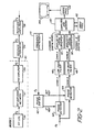
- a transmitter mixer 12 receives a signal F s , where F s is the transmitted radio frequency NMR signal, from a frequency synthesizer 10.
- the F s signal is heterodyned by the mixer to produce the F s signal, which is coupled by way of a controlled transmitter attenuator 14 to a transmitter amplifier 16.
- the transmitter mixer 12 and attenuator 14 are controlled by control signals provided by a pulse sequencer 20, which applies an r.f. enable signal to the mixer 12.
- the F s signal is amplified by the amplifier 16 and applied to the r.f. coil 24 in the magnet 30 in the form of a sequence of pulses formed under control of the pulse sequencer 20.
- the r.f. coil 24 applies the F s pulses to the subject being imaged.
- x, y, and z gradient coils 26, 28, and 29 are also located within the field of the magnet 30. These coils receive gradient control signals G x , Gy, and G Z from gradient signal amplifiers 22. The control signals are produced by the pulse sequencer 20.
- the NMR signals emitted by the nuclei of the material being imaged induce F s return signals in the r.f. coil 24. These return signals are coupled by way of an r.f. matching network 27 to a preamplifier 29, and on to a receiver attenuator 34 as shown in Figure 2.
- the received F s signals are amplified by an amplifier 36 and applied to quadrature phase detectors 42 and 44.
- the phase detectors receive two phase demodulating signals at respective 0° and 90° phase angles from a phase shifter 40, which receives an F s reference signal from the frequency synthesizer 10.
- the phase detectors 42 and 44 produce a channel A and a channel B signal, respectively.
- the baseband A and B signals are filtered by respective low pass filters 46 and 48, and the filtered signals are then sampled by respective analog to digital converters 50 and 52.
- the resultant channel A and channel B digital words are stored in a the memory of a computer 60.
- the channel A and B digital words are then combined and transformed to the frequency domain by a Fourier transform array processor 62.
- the resultant image signals are assembled in an image format by an image processor 64, and the processed image is displayed on a video monitor 66.
- the scan line there shown includes the two pulse sequence of a 90 degree pulse 70 and a 180 degree pulse 72. Free decay signals 71 and 73 follow the respective excitation pulses, and the desired spin-echo signal 75 is shown occurring during a sampling period T s .
- gradient coils 26, 28 and 29 of Figure 1 are energized by gradient pulses G x , Gy and G z as shown in Figure 3.
- the G x gradient pulse is applied following the 90 degree excitation pulse and during the time of acquisition of the spin-echo signal 75.
- the G z gradient pulse is applied during the first excitation pulse period to spatially identify the (x-y) plane which is to be imaged.
- the Gy gradient pulse is applied during the interval between the two excitation pulses to impose a spatially encoded phase factor onto the signal.
- each two pulse sequence is comprised of an a° pulse and a following ⁇ ° pulse, after which a spin echo signal is generated by the nuclei and detected by the r.f. coil.
- the a° pulse is a 90 degree pulse and the ⁇ ° pulse is a 180 degree pulse as shown in the scanning sequences of Figure 4.
- a 90 degree pulse 70 is transmitted followed by a relaxation period T .
- a free induction signal 71 is produced by the material being imaged, a signal which is not read by the receiver circuitry.
- a 180 degree pulse 72 is transmitted which exhibits a phase ⁇ .
- the 180 degree pulse should cause the bulk magnetization of the material being imaged to refocus in a direction opposite to that in which it was first "tipped" in the transverse (x-y) plane.
- an additional free decay signal 73 develops immediately following the end of the 180 degree pulse 72.
- the signal 73 rapidly decays, and is succeeded by the desired spin echo signal 75 as the bulk magnetization refocuses in the (x-y) plane.
- the spin-echo signal 75 peaks around a time ⁇ following the 180 degree pulse, and is detected and sampled during sampling period T s .
- the present inventors have found that favorable signal-to-noise conditions are attained by setting the sampling period duration T s at least equal to the time T , and setting T equal to T 2 /4 for the T 2 relaxation characteristic of the material being imaged.
- the sampling period T s is centered in time around the time of occurrance of the spin-echo signal peak.
- a second scanning sequence for line n+1 is performed.
- the line n+1 sequence differs from the line n sequence in that the 180 degree pulse 82 exhibits a phase of ⁇ +180°, in phase opposition to that of the preceding 180 degree pulse 72.
- the generated spin-echo signal 85 is detected and sampled during the T s sampling period of the line n+1 sequence.
- the desired spin-echo signal is unaffected by the different phasing of the 180 degree pulse 82.
- the unwanted free induction decay signal 83 has been phase-shifted by 180 degrees in comparison to the previous free induction decay signal 73.
- the detected spin-echo signals over a plurality of scan lines are sampled by the analog to digital converters 50 and 52 in Figure 2, which produces signal information in the form of discrete digital words.
- These digital words, A and B are arranged in a matrix array of complex numbers of the form Aj(t)+iBj(t), where t references the time of sampling during the sampling interval T s , and j refers to line numbers.
- a Fourier transformation is then performed to convert the time domain data to a spatially representative frequency domain using Fourier transformation.
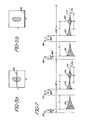
- the result of the alternate phasing of the 180 degree pulses 72 and 82 is to alternately phase encode the artifact signals 73 and 83. Without this phase encoding, the portions of the artifact signals occurring during the sample time T s would have no phase modulation, as they are induced at a time when there is no Gy pulse. In the process of Fourier transformation the randomly phased artifacts would manifest themselves as a distribution of signals about the zero frequency value in the center of the image in the y-direction, as indicated by the artifacts 90 in Figure 5a.
- the artifacts will manifest themselves as components located in the frequency spectrum at the limit of that employed in the Fourier transformation process, which causes them to appear at the edge of the image as shown by artifacts 92 in Figure 5b.
- the artifacts are thus removed from the center of the image, which is generally the region of primary interest.
- FIG. 6 depicts a plane of a raw data before Fourier transformation.
- the spin-echo signals for the various lines of data are shown as a group of generally harmonically related waveforms 100, each having a center along the time axis at t e .
- the undesired free decay artifact signals 102 At the left hand side of the time axis and along the edge of the Gy axis are the undesired free decay artifact signals 102. It is seen that, from line to line, the phasing of the artifact signals alternates at the same respective time location on each line.
- the phase alternation at the line rate encodes the artifacts by this frequency dependence, resulting in the appearance of the artifacts at the boundary of the Fourier transformed image plane.
- the artifacts are thereby removed from the center and other disadvantageous locations in the final image.
- Figure 7 is similar to Figure 4, in that it shows two lines of image data acquisition using two-pulse sequences.
- the first line n includes a 90 degree pulse 170 which exhibits a phase 0, followed by a 180 degree pulse 172.
- Free induction decay signals 171 and 173 are developed following each excitation pulse, and a spin-echo signal 175 is developed at time T after the 180 degree pulse 172.
- the second line n+1 in Figure 7 includes a 90 degree pulse 180 which exhibits a phase ())+180°.
- the 90 degree pulse 180 is followed by a 180 degree pulse 182.
- Free induction decay signals 181 and 183 are developed after each excitation pulse, and a spin-echo signal 185 is produced at time T after the 180 degree pulse 182.
- the alternate phasing of the 90 degree pulses from line to line phase modulates the unwanted free induction decay signals 173 and 183 and the spin-echo signals 175 and 185 in the following manner.
- the unwanted signals 173 and 183 are in phase at respective points in time following the 180 degree pulses from line to line.
- the spin-echo signals 175 and 185 are in respective phase opposition from line to line as shown in the Figure.
- the reference phase of the receiver is alternated from line to line. This may be done electronically, for instance, by shifting the reference phase applied to phase detector 42 and 44 in Figure 2 from line to line.
- phase detectors 42 anf 44 receive 0° and 90° phase'reference signals, and during line n+1 the phase detectors receive 180° and 270° phase reference signals.
- This phase alternation brings the spin-echo signals back into the same phase relationship during the sampling periods T S , and also shifts the unwanted free induction decay signals into phase opposition from line to line.
- the signals are then sampled during the T s sampling periods and the resulting data sets are subjected to Fourier transformation.
- the Fourier transformation of the phase modulated artifact signals cause them to appear at the edge of the image, since their spectral location is at the limit of that employed in the Fourier transformation process.
- the present inventors have found that it is preferential not to switch the phases of the phase detector reference signals, but to sample the signals and perform the phase shifting through software manipulation of the sampled data values in the computer 60.
- the software phase shifting is performed prior to Fourier transformation with the same result, and without the electronic complexity of electronic reference signal switching.
- This technique of alternating the phase of the a (90 degree) pulse from line to line also results in the elimination of D.C. signal offsets.
- the dashed lines 177 in Figure 7 indicate the true center line of the received signals.
- the effects of signal coupling and biasing in the receiver electronics may cause the true center line of the signals to be offset from the D.C. reference level 179 by the time the signals are digitized.
- this technique of artifact removal also causes the undesired D.C. offset to be modulated from line to line and appear at the edge of the image, provided that the offset is substantially constant during acquisition of the image.
- the lower waveform comprised of artifact signal 183' and spin-echo signal 185' is shown inverted relative to waveforms 183 and 185 in Figure 7; however, the illustrated effect is the same as that of phase shifting, as the signal in the preferred embodiment is software-inverted as it is passed to the memory of computer 60.
- the waveforms of the respective lines are shown with true center lines 177 and D.C. reference levels 179 and 179'.
- the D.C. reference level 179' in the lower waveform is shown above the true center line 177 since the waveform is shown in inverted form.
- the inverted representation shows that the artifact components 173 and 183' are modulated in phase alternation from line to line for artifact removal.
- Each sampled value in the line n waveform, V sn . has a value equal to the sum of the true center line signal level, v t , and the D.C. offset, Vo.
- each sampled value Vg n+i is equal to the true center line signal level v t minus the D.C. offset V o .
- the sign of the D.C. offset is seen to alternate from line to line.
- the D.C. offset is phase modulated at the Nyquist frequency of the phase-encoded dimension, and Fourier transformation will cause the effects of the D.C. offset to be removed to the frequency spectrum limit at the edge of the NMR image.
Abstract
Description
- This invention relates to techniques for removing unwanted artifact signal components from nuclear magnetic resonance (NMR) signals and, in particular, to techniques for artifact removal in NMR imaging systems through control of the phase relationships of radio frequency (r.f.) pulses in an NMR excitation sequence prior to Fourier transformation.
- The NMR technique may be used to form images of several characteristics of cellular and other materials. The object to be imaged is placed in a static magnetic field, whereby atomic nuclei align themselves with the static field. This field is disturbed in a controlled manner by excitation signals from a radio frequency coil, disturbing the nuclei from their equilibrium alignment. When the disturbing signals are removed, the nuclei begin to assume their original alignment, and emit energy in the process. The emitter signals are detected by the transmitting r.f. coil, or by another dedicated receiving r.f. coil. The signals are spatially encoded with magnetic field gradients. The detected signals are then processed to produce an image, typically of a plane or planes of the object being imaged.
- Ideally, detected NMR signals should contain only specific information relating to the characteristics of the material being imaged, uncontaminated by spurious signal components. Numerous efforts have been directed toward this goal. For instance, in the case of one dimensional pulse-Fourier transform NMR signals, an unwanted steady-state-free-precession type of refocussing can build up at the end of the desired free induction decay experiment. One approach toward eliminating this build-up is variation of the interpulse delay between excitation pulses.
- In two- and three-dimensional NMR imaging, approaches to enhanced resolution become more involved due to the presence of additional signals necessary for spatial resolution. In order to resolve specific locations in a plane of material, the material is subjected to time-varying and space-varying magnetic fields. The gradients (G) are generally linearly varying fields over the image volume. Spatial resolution in the x direction may be improved, for instance, by increasing the slope of the Gx field across the image. The increased spatial resolution in the x direction is accompanied by a corresponding reduction in the signal-to-noise ratio of the received signals, however, due to the wider bandwidth necessary to detect the broader range of NMR signal frequencies.
- A second technique for improving resolution is to increase the time window during which the NMR signal is sampled. By gathering more information in the time domain, a greater spectral resolution is available for Fourier transform processing, resulting in greater spectral resolution in the spatial representation of the NMR signals.
- In the time domain, two types of NMR signals can be produced. One type is the free induction signal, an' r.f. signal emitted immediately following a single r.f. excitation pulse. The second type of NMR signal is the multiple pulse response, of which the spin-echo signal is an example. Spin-echo signals may be induced, for instance, by tipping the bulk magnetization to the (x-y) plane with a 90° excitation pulse. Following the 90° pulse, a second, 180° pulse is applied, and the components of magnetization begin to refocus in the (x-y) plane and regain phase coherence momentarily. As they rephase, a spin-echo signal is developed. The emitted spin-echo signal resembles back-to-back free induction signals, with a signal peak occurring after the second r.f. pulse at a time equal to the time separation of the two r.f. pulses.
- Unlike the free induction signal, the sampling window for the spin echo signal may be adjusted in both directions (in time) relative to the signal peak. However, as the sampling window is extended back in time toward the second excitation pulse, free induction signal components generated from each of the two pulses individually, but primarily the second r.f. pulse are also present. These unwanted components are caused by r.f. magnetic field inhomogeneities, or by tip angle missettings. A perfect 180° pulse causes no free induction decay signal; however, it is not always possible to generate a perfect pulse. When these unwanted signal components are gathered and processed, they manifest themselves as artifacts through the NMR image. Accordingly, it is desirable to be able to widen the sampling window for the NMR signal to improve image resolution without artifacts from free induction decay signal components.
- A technique for eliminating such artifacs in NMR spectroscopy is described in the article "Suppression of Artifacts in Two-Dimensional J Spectroscopy", by G. Bodenhausen, et al., published in the Jouranl of Magnetic Resonance 2, pp. 511-14 (1977). In the technique there described, the phase of the second excitation pulse, the phase of the receiver reference signal, or preferably both, are alternated over a number of different data acquisitions. The data recovered from the different acquisitions, preferably four in number, is summed, resulting in coherent addition of spin-echoes and phase cancellation of artifacts.
- The foregoing technique requires that as many as four excitation pulse sequences of two pulses each be performed in order to provide for proper constructive reinforcement and cancellation. In NMR imaging, the time required to perform four sequences may be insubstantial for scans of small areas, but the aggregate time allocation may be significant when performing scans of large areas or three dimensions. This is due to the physical principles inherent in NMR imaging. After each two-pulse sequence, time must be allotted for the disturbed spin system to relax. The allocated time for relaxation is governed by the immutable spin-spin and spin-lattice relaxation time constants. Hence, the use. of this NMR spectroscopy technique for artifact cancellation would impose a severe time constraint in NMR imaging.
- Thus, the Bodenhausen paper discloses a nuclear magnetic resonance imaging system comprising:
- means for exciting an imaging subject by a two pulse excitation sequence in an excitation period;
- means for detecting resultant NMR signals in a subsequent data collection period and collecting said NMR signals into data lines;
- a source of gradient field signals for spatially encoding said NMR signals;
- means for performing a Fourier transformation of said data lines to produce an image of the subject; and
- control means arranged to alternate the phasing of said excitation pulse sequence.
- The NMR imaging system of the present invention is characterised in that:
- the control means is arranged to alternate the phasing of said excitation pulse sequence so that, in alternating data collection periods following each two pulse sequence, undesired artifact signal components and desired NMR signals exhibit a first and second phase relationship respectively and said data lines, prior to Fourier transformation, are arranged with the artifact signal components exhibiting a phasing which varies from lines to line whereby on Fourier transformation said artifact signal components are located away from the center of said NMR image.
- Preferably, the control means is arranged to alternate the phase of the second pulse in the two pulse sequence from one excitation pulse sequence to the next.
- Alternatively, the control means may be arranged to alternate the phase of the first pulse in the two pulse sequence from one excitation pulse sequence to the next and the detection means includes means for inverting the phase of alternating ones of the data lines prior to Fourier transformation.
- Preferably, the NMR system is arranged to perform said Fourier transformation at least in the direction of said phase alternation.
- Conveniently, the undesired artifact signal components are free decay components and said desired NMR signals are spin-echo signals.
- The Bodenhausen paper also discloses a method for reducing the effects of undesired artifact signal components in an NMR signal, comprising:
- acquiring a plurality of sequences of line information in response to a series of two pulse excitation sequences in which the phasing of the excitation pulse sequence is alternated; and performing a Fourier transformation of said acquired line information so as to form an image,
- The method of the present invention is characterised in that the phasing of the excitation pulse sequence alternates from line to line, and the Fourier transformation is performed in at least the direction of alternation of said artifact signal component.
- Preferably, the artifact signal components are free decay signals which are removed from the center of the image.
- Conveniently, the phase of the second pulse in the two pulse sequence is alternated from one sequence to the next.
- Alternatively, the phase of the first pulse in the two pulse sequence may be alternated from one sequence to the next and the phase of the detected signals is alternated from one phase to the next so as to phase-encode detected artifact signal components with a phasing which alternates from line to line.
- In accordance with the principles of a preferred embodiment of the present invention, the artifact components are made to alternate phase coherently by alternation of the phase of a r.f. excitation signal. The desired spin-echo signals possess no such alternation. A two- or three-dimensional Fourier transformation is then performed with respect to the direction of this alternation, resulting in the reconstruction of the phase coherent artifact components at the edge of the image.
- In the drawings:
- Figure 1 illustrates in block diagram form the transmission portion of an NMR imaging system;
- Figure 2 illustrates in block diagram form the receiver portion of an NMR imaging system;
- Figure 3 illustrates excitation pulse gradient signal, and NMR signal waveforms;
- Figure 4 illustrates waveforms depicting NMR system operation when the phase of a 180° pulse is alternated, from line to line;
- Figures 5a and 5b illustrate the effect of artifact relocation in accordance with the principles of the present invention;
- Figure 6 shows raw data waveforms in the time domain prior to Fourier transformation.
- Figure 7 illustrates waveforms depicting NMR system operation when the phase of a 90° pulse is alternated from line to line; and
- Figure 8 represents the effects of the 90° pulse phase alternation of Figure 7.
- Referring to Figure 1, the transmission portion of an NMR imaging system is shown. A transmitter mixer 12 receives a signal Fs, where Fs is the transmitted radio frequency NMR signal, from a
frequency synthesizer 10. The Fs signal is heterodyned by the mixer to produce the Fs signal, which is coupled by way of a controlledtransmitter attenuator 14 to a transmitter amplifier 16. The transmitter mixer 12 andattenuator 14 are controlled by control signals provided by apulse sequencer 20, which applies an r.f. enable signal to the mixer 12. The Fs signal is amplified by the amplifier 16 and applied to the r.f.coil 24 in themagnet 30 in the form of a sequence of pulses formed under control of thepulse sequencer 20. The r.f.coil 24 applies the Fs pulses to the subject being imaged. - Also located within the field of the
magnet 30 are x, y, and z gradient coils 26, 28, and 29. These coils receive gradient control signals Gx, Gy, and GZ fromgradient signal amplifiers 22. The control signals are produced by thepulse sequencer 20. - The NMR signals emitted by the nuclei of the material being imaged induce Fs return signals in the r.f.
coil 24. These return signals are coupled by way of an r.f. matching network 27 to apreamplifier 29, and on to areceiver attenuator 34 as shown in Figure 2. The received Fs signals are amplified by anamplifier 36 and applied toquadrature phase detectors 42 and 44. The phase detectors receive two phase demodulating signals at respective 0° and 90° phase angles from aphase shifter 40, which receives an Fs reference signal from thefrequency synthesizer 10. Thephase detectors 42 and 44 produce a channel A and a channel B signal, respectively. The baseband A and B signals are filtered by respective low pass filters 46 and 48, and the filtered signals are then sampled by respective analog todigital converters computer 60. The channel A and B digital words are then combined and transformed to the frequency domain by a Fourier transform array processor 62. The resultant image signals are assembled in an image format by animage processor 64, and the processed image is displayed on avideo monitor 66. - Referring to Figure 3, the scan line there shown includes the two pulse sequence of a 90 degree pulse 70 and a 180 degree pulse 72. Free decay signals 71 and 73 follow the respective excitation pulses, and the desired spin-
echo signal 75 is shown occurring during a sampling period Ts. - For spatial identity of the recovered signals, gradient coils 26, 28 and 29 of Figure 1 are energized by gradient pulses Gx, Gy and Gz as shown in Figure 3. The Gx gradient pulse is applied following the 90 degree excitation pulse and during the time of acquisition of the spin-
echo signal 75. The Gz gradient pulse is applied during the first excitation pulse period to spatially identify the (x-y) plane which is to be imaged. The Gy gradient pulse is applied during the interval between the two excitation pulses to impose a spatially encoded phase factor onto the signal. - In the arrangement of Figure 1, the nuclei of the material being imaged are excited by two-pulse sequences in accordance with the principles of the present invention, causing them to emit NMR signals in the form of spin echoes. Each two pulse sequence is comprised of an a° pulse and a following β° pulse, after which a spin echo signal is generated by the nuclei and detected by the r.f. coil. In a preferred embodiment the a° pulse is a 90 degree pulse and the β° pulse is a 180 degree pulse as shown in the scanning sequences of Figure 4. In the line n sequence, a 90 degree pulse 70 is transmitted followed by a relaxation period T. During the relaxation period a
free induction signal 71 is produced by the material being imaged, a signal which is not read by the receiver circuitry. At the end of the relaxation period T a 180 degree pulse 72 is transmitted which exhibits a phase φ. Ideally the 180 degree pulse should cause the bulk magnetization of the material being imaged to refocus in a direction opposite to that in which it was first "tipped" in the transverse (x-y) plane. However, due to inhomogeneities in the r.f. magnetic field at the location of the nuclei and tip angle missettings, an additionalfree decay signal 73 develops immediately following the end of the 180 degree pulse 72. Thesignal 73 rapidly decays, and is succeeded by the desiredspin echo signal 75 as the bulk magnetization refocuses in the (x-y) plane. The spin-echo signal 75 peaks around a time τfollowing the 180 degree pulse, and is detected and sampled during sampling period Ts. - Although it is possible to detect and sample the spin-echo signal during the entire period following the 180 degree pulse 72, it has been found that such sampling will be adversely affected by the free
induction decay signal 73 following the 180 degree pulse 72. Extending the sampling period later in time results in signal acquisition at a time when the spin echo signal is greatly diminished due to T2 decay, or spin-spin relaxation. To avoid extending the sampling period to an earlier point in time, a steeper gradient magnetic field and increased bandwidth are generally used for signal detection. The increased bandwidth over a fixed number of resolved picture elements results in increased noise per image element. The present inventors have found that favorable signal-to-noise conditions are attained by setting the sampling period duration Ts at least equal to the time T, and setting T equal to T2/4 for the T2 relaxation characteristic of the material being imaged. The sampling period Ts is centered in time around the time of occurrance of the spin-echo signal peak. - After the line n sequence a second scanning sequence for line n+1 is performed. The line n+1 sequence differs from the line n sequence in that the 180
degree pulse 82 exhibits a phase of φ+180°, in phase opposition to that of the preceding 180 degree pulse 72. The generated spin-echo signal 85 is detected and sampled during the Ts sampling period of the line n+1 sequence. The desired spin-echo signal is unaffected by the different phasing of the 180degree pulse 82. However, the unwanted freeinduction decay signal 83 has been phase-shifted by 180 degrees in comparison to the previous freeinduction decay signal 73. - The detected spin-echo signals over a plurality of scan lines are sampled by the analog to
digital converters - The result of the alternate phasing of the 180
degree pulses 72 and 82 is to alternately phase encode the artifact signals 73 and 83. Without this phase encoding, the portions of the artifact signals occurring during the sample time Ts would have no phase modulation, as they are induced at a time when there is no Gy pulse. In the process of Fourier transformation the randomly phased artifacts would manifest themselves as a distribution of signals about the zero frequency value in the center of the image in the y-direction, as indicated by theartifacts 90 in Figure 5a. However, when the phase of the artifact components alternates by 180 degrees from line to line, the artifacts will manifest themselves as components located in the frequency spectrum at the limit of that employed in the Fourier transformation process, which causes them to appear at the edge of the image as shown byartifacts 92 in Figure 5b. The artifacts are thus removed from the center of the image, which is generally the region of primary interest. - The effect of Fourier transformation is representatively illustrated in Figure 6, which depicts a plane of a raw data before Fourier transformation. The spin-echo signals for the various lines of data are shown as a group of generally harmonically
related waveforms 100, each having a center along the time axis at te. At the left hand side of the time axis and along the edge of the Gy axis are the undesired free decay artifact signals 102. It is seen that, from line to line, the phasing of the artifact signals alternates at the same respective time location on each line. When Fourier transformation is performed with respect to Gy, the phase alternation at the line rate encodes the artifacts by this frequency dependence, resulting in the appearance of the artifacts at the boundary of the Fourier transformed image plane. The artifacts are thereby removed from the center and other disadvantageous locations in the final image. - A preferred technique in accordance with the principles of the present invention for removing artifacts from an NMR image, and for simultaneously eliminating the effects of D.C. offsets of the received signal, is illustrated in Figures 7 and 8. Figure 7 is similar to Figure 4, in that it shows two lines of image data acquisition using two-pulse sequences. The first line n includes a 90 degree pulse 170 which exhibits a phase 0, followed by a 180 degree pulse 172. Free induction decay signals 171 and 173 are developed following each excitation pulse, and a spin-
echo signal 175 is developed at time T after the 180 degree pulse 172. - The second line n+1 in Figure 7 includes a 90
degree pulse 180 which exhibits a phase ())+180°. The 90degree pulse 180 is followed by a 180degree pulse 182. Free induction decay signals 181 and 183 are developed after each excitation pulse, and a spin-echo signal 185 is produced at time T after the 180degree pulse 182. - The alternate phasing of the 90 degree pulses from line to line phase modulates the unwanted free induction decay signals 173 and 183 and the spin-
echo signals unwanted signals echo signals detector 42 and 44 in Figure 2 from line to line. During line n, for example, the phase detectors 42anf 44 receive 0° and 90° phase'reference signals, and during line n+1 the phase detectors receive 180° and 270° phase reference signals. This phase alternation brings the spin-echo signals back into the same phase relationship during the sampling periods TS, and also shifts the unwanted free induction decay signals into phase opposition from line to line. The signals are then sampled during the Ts sampling periods and the resulting data sets are subjected to Fourier transformation. As before, the Fourier transformation of the phase modulated artifact signals cause them to appear at the edge of the image, since their spectral location is at the limit of that employed in the Fourier transformation process. - The present inventors have found that it is preferential not to switch the phases of the phase detector reference signals, but to sample the signals and perform the phase shifting through software manipulation of the sampled data values in the
computer 60. The software phase shifting is performed prior to Fourier transformation with the same result, and without the electronic complexity of electronic reference signal switching. - This technique of alternating the phase of the a (90 degree) pulse from line to line also results in the elimination of D.C. signal offsets. The dashed
lines 177 in Figure 7 indicate the true center line of the received signals. As the signals proceed through the receiver, the effects of signal coupling and biasing in the receiver electronics may cause the true center line of the signals to be offset from theD.C. reference level 179 by the time the signals are digitized. However, this technique of artifact removal also causes the undesired D.C. offset to be modulated from line to line and appear at the edge of the image, provided that the offset is substantially constant during acquisition of the image. - This effect is representatively shown by the waveforms of Figure 8, which shows line n and line n+1 signal waveforms referenced to a common sampling period Ts. The dots on the waveform indicate sampling times. The upper waveform is comprised of
artifact signal 173 most visible during time segment tART, and spin-echo signal 175 during time segment tSE. For ease of illustration the two signal segments are shown as being monotonal, although it is recognized that in an actual embodiment the signal during time segment TART will be a complex waveform of both the spin-echo and artifact signals. Also for ease of comparative illustration, the lower waveform comprised of artifact signal 183' and spin-echo signal 185' is shown inverted relative towaveforms computer 60. - In Figure 8, the waveforms of the respective lines are shown with
true center lines 177 andD.C. reference levels 179 and 179'. The D.C. reference level 179' in the lower waveform is shown above thetrue center line 177 since the waveform is shown in inverted form. The inverted representation shows that theartifact components 173 and 183' are modulated in phase alternation from line to line for artifact removal. - Each sampled value in the line n waveform, Vsn. has a value equal to the sum of the true center line signal level, vt, and the D.C. offset, Vo. In the line n+1 waveform, each sampled value Vgn+i is equal to the true center line signal level vt minus the D.C. offset Vo. The sign of the D.C. offset is seen to alternate from line to line. Thus, the D.C. offset is phase modulated at the Nyquist frequency of the phase-encoded dimension, and Fourier transformation will cause the effects of the D.C. offset to be removed to the frequency spectrum limit at the edge of the NMR image.
Claims (9)
Priority Applications (1)
| Application Number | Priority Date | Filing Date | Title |
|---|---|---|---|
| AT84307728T ATE32791T1 (en) | 1983-11-09 | 1984-11-08 | REMOVAL OF PARASITIC SIGNALS IN NUCLEAR MAGNETIC RESONANCE. |
Applications Claiming Priority (2)
| Application Number | Priority Date | Filing Date | Title |
|---|---|---|---|
| US06/550,522 US4616182A (en) | 1983-11-09 | 1983-11-09 | Nuclear magnetic resonance signal artifact removal |
| US550522 | 1983-11-09 |
Publications (2)
| Publication Number | Publication Date |
|---|---|
| EP0145277A1 EP0145277A1 (en) | 1985-06-19 |
| EP0145277B1 true EP0145277B1 (en) | 1988-03-02 |
Family
ID=24197519
Family Applications (1)
| Application Number | Title | Priority Date | Filing Date |
|---|---|---|---|
| EP84307728A Expired EP0145277B1 (en) | 1983-11-09 | 1984-11-08 | Nuclear magnetic resonance signal artifact removal |
Country Status (4)
| Country | Link |
|---|---|
| US (1) | US4616182A (en) |
| EP (1) | EP0145277B1 (en) |
| AT (1) | ATE32791T1 (en) |
| DE (1) | DE3469602D1 (en) |
Cited By (1)
| Publication number | Priority date | Publication date | Assignee | Title |
|---|---|---|---|---|
| EP0182267B1 (en) | 1984-11-21 | 1990-03-07 | General Electric Company | A method for removing the effects of baseline error components in nmr imaging applications |
Families Citing this family (16)
| Publication number | Priority date | Publication date | Assignee | Title |
|---|---|---|---|---|
| JPS5938637A (en) * | 1982-08-28 | 1984-03-02 | Toshiba Corp | Nuclear magnetic resonance apparatus |
| DE3514542A1 (en) * | 1985-04-22 | 1986-10-23 | Siemens AG, 1000 Berlin und 8000 München | METHOD AND DEVICE FOR COMPOSING AN MR IMAGE FROM BREATH-CONTROLLED IMAGE DATA |
| US4721911A (en) * | 1985-07-26 | 1988-01-26 | Siemens Aktiengesellschaft | Nuclear magnetic resonance tomography apparatus |
| NL8601845A (en) * | 1986-07-15 | 1988-02-01 | Philips Nv | MRI METHOD AND APPARATUS FOR REDUCING ARTEFACTS BY PHASE CODING |
| JPS63109847A (en) * | 1986-10-29 | 1988-05-14 | 株式会社日立メデイコ | Nuclear magnetic resonance imaging apparatus |
| US4733185A (en) * | 1987-06-01 | 1988-03-22 | General Electric Company | Methods for localization in NMR spectroscopy |
| US4792758A (en) * | 1987-11-19 | 1988-12-20 | Picker International, Inc. | Steady-state echo magnetic resonance imaging |
| US4862081A (en) * | 1988-11-23 | 1989-08-29 | Picker International, Inc. | DC artifact removal in magnetic resonance imaging |
| DE4014220A1 (en) * | 1989-05-16 | 1990-11-22 | Siemens Ag | Transfer function unfolding during image generation - using NMR and Fourier transformation of divided measurement matrix, then addition of factored intermediate matrices |
| DE4005675C2 (en) * | 1990-02-22 | 1995-06-29 | Siemens Ag | Process for the suppression of artifacts in the generation of images by means of nuclear magnetic resonance |
| US5245283A (en) * | 1991-08-07 | 1993-09-14 | Picker International, Inc. | Technique for shifting out-of-slice artifacts to the edge of the field of view |
| DE4205780C2 (en) * | 1992-02-26 | 1995-02-16 | Spectrospin Ag | Method for generating NMR signals with a coherent phase profile by combining high-frequency pulses with an incoherent phase profile |
| EP0871895B1 (en) | 1995-02-24 | 2008-10-08 | QRSciences Pty. Limited | Method of and apparatus for nuclear quadrupole resonance testing a sample |
| US5541513A (en) * | 1995-04-14 | 1996-07-30 | General Electric Company | MRI center point artifact elimination using realtime receiver phase control |
| WO2014008315A1 (en) * | 2012-07-06 | 2014-01-09 | Acuitas Medical Limited | Optimised pulse sequences for evaluating spatial frequency content of a selectively excited internal volume |
| JP6234214B2 (en) * | 2013-12-24 | 2017-11-22 | 株式会社日立製作所 | Magnetic resonance imaging system |
Family Cites Families (4)
| Publication number | Priority date | Publication date | Assignee | Title |
|---|---|---|---|---|
| BE756934R (en) * | 1969-10-15 | 1971-03-16 | Commissariat Energie Atomique | NEW PROCESS FOR DYNAMIC POLARIZATION OF THE ATOMIC NUCLEUS OF A SOLVENT, ESPECIALLY OF A HYDROGENIC SOLVENT, AND MAGNETOMETERS FOR MEASURING THE INTENSITY OF LOW MAGNETIC FIELDS, PARTICULARLY OF THE EARTH MAGNETIC FIELD, IMPLEMENTING THIS PROCEDURE |
| DD137281A1 (en) * | 1978-06-19 | 1979-08-22 | Rudolf Mueller | METHOD AND ARRANGEMENT FOR MEASURING HIGH DEFLECTIVE MAGNETIC CORE RESONANCE |
| US4318043A (en) * | 1978-07-20 | 1982-03-02 | The Regents Of The University Of California | Method and apparatus for rapid NMR imaging of nuclear densities within an object |
| US4301410A (en) * | 1979-09-28 | 1981-11-17 | International Business Machines Corporation | Spin imaging in solids using synchronously rotating field gradients and samples |
-
1983
- 1983-11-09 US US06/550,522 patent/US4616182A/en not_active Expired - Lifetime
-
1984
- 1984-11-08 EP EP84307728A patent/EP0145277B1/en not_active Expired
- 1984-11-08 AT AT84307728T patent/ATE32791T1/en not_active IP Right Cessation
- 1984-11-08 DE DE8484307728T patent/DE3469602D1/en not_active Expired
Cited By (1)
| Publication number | Priority date | Publication date | Assignee | Title |
|---|---|---|---|---|
| EP0182267B1 (en) | 1984-11-21 | 1990-03-07 | General Electric Company | A method for removing the effects of baseline error components in nmr imaging applications |
Also Published As
| Publication number | Publication date |
|---|---|
| DE3469602D1 (en) | 1988-04-07 |
| ATE32791T1 (en) | 1988-03-15 |
| EP0145277A1 (en) | 1985-06-19 |
| US4616182A (en) | 1986-10-07 |
Similar Documents
| Publication | Publication Date | Title |
|---|---|---|
| EP0145277B1 (en) | Nuclear magnetic resonance signal artifact removal | |
| DE19821780B4 (en) | Correction of artifacts caused by Maxwell terms in cut-shift echo-planar imaging | |
| EP0091008B1 (en) | Method of three-dimensional nmr imaging using selective excitation | |
| US4521733A (en) | NMR Imaging of the transverse relaxation time using multiple spin echo sequences | |
| US4748410A (en) | Rapid NMR imaging system | |
| US5942897A (en) | Magnetic resonance imaging apparatus | |
| US4689567A (en) | NMR Fourier imaging from multiple echoes | |
| US5652516A (en) | Spectroscopic magnetic resonance imaging using spiral trajectories | |
| US6472872B1 (en) | Real-time shimming of polarizing field in magnetic resonance system | |
| US4628262A (en) | Multiple echo chemical shift imaging | |
| EP0145276B1 (en) | Complex quotient nuclear magnetic resonance imaging | |
| US4612504A (en) | Method for removing the effects of baseline error components in NMR imaging applications | |
| US5548215A (en) | MR imaging apparatus | |
| US4891595A (en) | Restricted volume imaging | |
| US5309101A (en) | Magnetic resonance imaging in an inhomogeneous magnetic field | |
| JPH0337406B2 (en) | ||
| US4616183A (en) | Method for reducing baseline error components in NMR signals | |
| EP1094331A2 (en) | Mri apparatus | |
| US4959611A (en) | Out-of-slice artifact reduction technique for magnetic resonance imagers | |
| US4695800A (en) | Non harmonic NMR spin echo imaging | |
| US5541512A (en) | Method for the prevention of registration artifacts due to motion in magnetic resonance images | |
| EP0955556B1 (en) | Ghost artifact reduction in fact spin echo MRI sequences | |
| US4714884A (en) | Method of eliminating effects of spurious NMR signals caused by imperfect 180 degree RF pulses | |
| EP0182873A1 (en) | Nmr fourier imaging from multiple echoes | |
| US4916396A (en) | Magnetic resonance imaging method |
Legal Events
| Date | Code | Title | Description |
|---|---|---|---|
| PUAI | Public reference made under article 153(3) epc to a published international application that has entered the european phase |
Free format text: ORIGINAL CODE: 0009012 |
|
| AK | Designated contracting states |
Designated state(s): AT BE CH DE FR GB IT LI LU NL SE |
|
| 17P | Request for examination filed |
Effective date: 19851122 |
|
| 17Q | First examination report despatched |
Effective date: 19861218 |
|
| GRAA | (expected) grant |
Free format text: ORIGINAL CODE: 0009210 |
|
| AK | Designated contracting states |
Kind code of ref document: B1 Designated state(s): AT BE CH DE FR GB IT LI LU NL SE |
|
| REF | Corresponds to: |
Ref document number: 32791 Country of ref document: AT Date of ref document: 19880315 Kind code of ref document: T |
|
| REF | Corresponds to: |
Ref document number: 3469602 Country of ref document: DE Date of ref document: 19880407 |
|
| ET | Fr: translation filed | ||
| ITF | It: translation for a ep patent filed |
Owner name: SOCIETA' ITALIANA BREVETTI S.P.A. |
|
| PG25 | Lapsed in a contracting state [announced via postgrant information from national office to epo] |
Ref country code: LU Free format text: LAPSE BECAUSE OF NON-PAYMENT OF DUE FEES Effective date: 19881130 |
|
| PLBI | Opposition filed |
Free format text: ORIGINAL CODE: 0009260 |
|
| 26 | Opposition filed |
Opponent name: SIEMENS AKTIENGESELLSCHAFT, BERLIN UND MUENCHEN Effective date: 19881202 |
|
| NLR1 | Nl: opposition has been filed with the epo |
Opponent name: SIEMENS AG |
|
| PGFP | Annual fee paid to national office [announced via postgrant information from national office to epo] |
Ref country code: AT Payment date: 19891114 Year of fee payment: 6 |
|
| PGFP | Annual fee paid to national office [announced via postgrant information from national office to epo] |
Ref country code: BE Payment date: 19891117 Year of fee payment: 6 |
|
| PGFP | Annual fee paid to national office [announced via postgrant information from national office to epo] |
Ref country code: LU Payment date: 19891211 Year of fee payment: 6 |
|
| PG25 | Lapsed in a contracting state [announced via postgrant information from national office to epo] |
Ref country code: AT Effective date: 19901108 |
|
| PLBN | Opposition rejected |
Free format text: ORIGINAL CODE: 0009273 |
|
| STAA | Information on the status of an ep patent application or granted ep patent |
Free format text: STATUS: OPPOSITION REJECTED |
|
| PGFP | Annual fee paid to national office [announced via postgrant information from national office to epo] |
Ref country code: SE Payment date: 19901129 Year of fee payment: 7 |
|
| PG25 | Lapsed in a contracting state [announced via postgrant information from national office to epo] |
Ref country code: BE Effective date: 19901130 |
|
| PGFP | Annual fee paid to national office [announced via postgrant information from national office to epo] |
Ref country code: CH Payment date: 19901203 Year of fee payment: 7 |
|
| 27O | Opposition rejected |
Effective date: 19901019 |
|
| NLR2 | Nl: decision of opposition | ||
| BERE | Be: lapsed |
Owner name: TECHNICARE CORP. Effective date: 19901130 |
|
| PG25 | Lapsed in a contracting state [announced via postgrant information from national office to epo] |
Ref country code: SE Effective date: 19911109 |
|
| ITTA | It: last paid annual fee | ||
| PG25 | Lapsed in a contracting state [announced via postgrant information from national office to epo] |
Ref country code: LI Effective date: 19911130 Ref country code: CH Effective date: 19911130 |
|
| PGFP | Annual fee paid to national office [announced via postgrant information from national office to epo] |
Ref country code: NL Payment date: 19911130 Year of fee payment: 8 |
|
| REG | Reference to a national code |
Ref country code: GB Ref legal event code: 732 |
|
| REG | Reference to a national code |
Ref country code: GB Ref legal event code: 732 |
|
| NLT1 | Nl: modifications of names registered in virtue of documents presented to the patent office pursuant to art. 16 a, paragraph 1 |
Owner name: ETHICON INC. TE SOMERVILLE, NEW JERSEY, VER. ST. V |
|
| REG | Reference to a national code |
Ref country code: FR Ref legal event code: TP |
|
| ITPR | It: changes in ownership of a european patent |
Owner name: CESSIONE;SIEMENS AKTIENGESELLSCHAFT |
|
| NLS | Nl: assignments of ep-patents |
Owner name: SIEMENS AKTIENGESELLSCHAFT TE BERLIJN EN MUENCHEN, |
|
| REG | Reference to a national code |
Ref country code: CH Ref legal event code: PL |
|
| PG25 | Lapsed in a contracting state [announced via postgrant information from national office to epo] |
Ref country code: NL Effective date: 19930601 |
|
| NLV4 | Nl: lapsed or anulled due to non-payment of the annual fee | ||
| EUG | Se: european patent has lapsed |
Ref document number: 84307728.0 Effective date: 19920604 |
|
| PGFP | Annual fee paid to national office [announced via postgrant information from national office to epo] |
Ref country code: GB Payment date: 19991116 Year of fee payment: 16 |
|
| PGFP | Annual fee paid to national office [announced via postgrant information from national office to epo] |
Ref country code: FR Payment date: 19991126 Year of fee payment: 16 |
|
| PG25 | Lapsed in a contracting state [announced via postgrant information from national office to epo] |
Ref country code: GB Free format text: LAPSE BECAUSE OF NON-PAYMENT OF DUE FEES Effective date: 20001108 |
|
| PGFP | Annual fee paid to national office [announced via postgrant information from national office to epo] |
Ref country code: DE Payment date: 20010122 Year of fee payment: 17 |
|
| GBPC | Gb: european patent ceased through non-payment of renewal fee |
Effective date: 20001108 |
|
| PG25 | Lapsed in a contracting state [announced via postgrant information from national office to epo] |
Ref country code: FR Free format text: LAPSE BECAUSE OF NON-PAYMENT OF DUE FEES Effective date: 20010731 |
|
| REG | Reference to a national code |
Ref country code: FR Ref legal event code: ST |
|
| PG25 | Lapsed in a contracting state [announced via postgrant information from national office to epo] |
Ref country code: DE Free format text: LAPSE BECAUSE OF NON-PAYMENT OF DUE FEES Effective date: 20020702 |
|
| APAH | Appeal reference modified |
Free format text: ORIGINAL CODE: EPIDOSCREFNO |