EP0145246B1 - Method and apparatus for supplying cooling air in a glass sheet quench - Google Patents
Method and apparatus for supplying cooling air in a glass sheet quench Download PDFInfo
- Publication number
- EP0145246B1 EP0145246B1 EP84307593A EP84307593A EP0145246B1 EP 0145246 B1 EP0145246 B1 EP 0145246B1 EP 84307593 A EP84307593 A EP 84307593A EP 84307593 A EP84307593 A EP 84307593A EP 0145246 B1 EP0145246 B1 EP 0145246B1
- Authority
- EP
- European Patent Office
- Prior art keywords
- blower
- gas
- speed
- quench
- length
- Prior art date
- Legal status (The legal status is an assumption and is not a legal conclusion. Google has not performed a legal analysis and makes no representation as to the accuracy of the status listed.)
- Expired
Links
- 238000010791 quenching Methods 0.000 title claims description 77
- 239000011521 glass Substances 0.000 title claims description 73
- 238000001816 cooling Methods 0.000 title claims description 29
- 238000000034 method Methods 0.000 title claims description 12
- 230000000171 quenching effect Effects 0.000 claims description 33
- 230000001133 acceleration Effects 0.000 claims description 2
- 238000005496 tempering Methods 0.000 description 20
- 239000005357 flat glass Substances 0.000 description 3
- 238000010438 heat treatment Methods 0.000 description 3
- 239000005347 annealed glass Substances 0.000 description 1
- 239000005328 architectural glass Substances 0.000 description 1
- 230000007423 decrease Effects 0.000 description 1
- 238000004519 manufacturing process Methods 0.000 description 1
- 230000003534 oscillatory effect Effects 0.000 description 1
- 230000003763 resistance to breakage Effects 0.000 description 1
- 239000005341 toughened glass Substances 0.000 description 1
Images


Classifications
-
- C—CHEMISTRY; METALLURGY
- C03—GLASS; MINERAL OR SLAG WOOL
- C03B—MANUFACTURE, SHAPING, OR SUPPLEMENTARY PROCESSES
- C03B27/00—Tempering or quenching glass products
- C03B27/04—Tempering or quenching glass products using gas
-
- C—CHEMISTRY; METALLURGY
- C03—GLASS; MINERAL OR SLAG WOOL
- C03B—MANUFACTURE, SHAPING, OR SUPPLEMENTARY PROCESSES
- C03B27/00—Tempering or quenching glass products
- C03B27/04—Tempering or quenching glass products using gas
- C03B27/0417—Controlling or regulating for flat or bent glass sheets
Definitions
- This invention relates to method and apparatus to improve glass sheet quenching and cooling and, in particular, to method and apparatus for supplying cooling air to improve glass sheet quenching and cooling.
- Glass sheets are quenched to provide tempering or heat strengthening in order to increase the mechanical strength of the glass and hence provide an increased resistance to breakage as compared to annealed glass.
- the sudden cooling process gives the glass sheets high compressive forces at their surfaces. Tempered glass sheets are less susceptible to breakage and break into small pieces that are dull and relatively harmless instead of into large pieces as in the case of untempered glass.
- quenching gas In tempering, quenching gas is impinged with the opposite surfaces of the glass sheet to provide rapid cooling thereof such that the finally cooled glass sheet has compressive forces at its surfaces and tensile forces at its center.
- tempering and heat strengthening can be performed on flat glass sheets such as are conveniently used for architectural purposes and on bent glass sheets such as are conveniently used for vehicle windows.
- Glass sheet quenches conventionally include opposed blastheads, each of which have elongated plenum housings or banks of nozzles that are spaced from each other and supply pressurized quenching gas to a heated glass sheet positioned between the blastheads.
- the plenums are spaced from each other to leave room for spent quenching gas to flow away from the glass sheet and between the plenums for flow out from between the blastheads.
- the quenching gas is supplied in discrete jets that are spaced along the length of each plenum housing as disclosed by US-A-3,936,291.
- Quenching jets are normally supplied in a parallel relationship to each other to provide tempering of flat glass sheets which are positioned between the opposed blastheads of the quench, extending in a perpendicular relationship to the quenching jets.
- One possible solution to this increased need for quenching gas is to reduce the length of the device providing the quench to something less than the largest glass length and follow it by a full-length cooler.
- the glass may be passed through the quench at a rate sufficiently slow to impart the optimal degree of tempering and thereafter into the cooler where it oscillates until the next piece of glass is passed therethrough.
- US-A-4004901 discloses a method for operating a gas supply system, and a gas supply system for a glass sheet quench according to the preamble of claims 1 and 7 wherein the glass sheet quench has a quench cycle and a cooling cycle and wherein the system includes a drive system, a variable speed blower and opposed blastheads which are spaced from each other and supply pressurized gas from the blower to a heated glass sheet positioned between the blastheads.
- the drive system is operated on a duty cycle rather than on a continuous basis, and the peak power output of the drive system during the quenching cycle is greater than its rated power output to thereby reduce the initial and operating costs, and size and power requirements of the drive system.
- the glass sheet quench is able to quench and cool the glass sheets after receiving the glass sheets at a speed fast enough so that flatness control is not a significant problem and therein the size and power requirements of the drive system are minimized.
- a method for operating a gas supply system for a glass sheet quench having a quench cycle and a cooling cycle including a drive system of a variable speed blower and opposed blastheads which are spaced from each other and supply pressurized gas from the blower to a heated glass sheet (G) positioned between the blastheads, characterised by operating the blower at a first speed for a first length of time at substantially full power, causing the blower to slow down to a second speed for a second length of time, restricting the flow of gas to the blower while accelerating it to the first speed then allowing the gas to flow, and thereafter repeating the cycle.
- G heated glass sheet
- the present invention further provides a gas supply system for a glass sheet quench including a drive system of a variable speed blower and opposed blastheads which are spaced from each other and supply pressurized gas from the blower to a heated glass sheet (G) positioned between the blastheads, characterised in that the gas supply system further includes:
- control means for controlling the restricting means when changing the speed of the blower and then to permit increased flow of the pressurized gas, said control means also controlling the drive system to operate the blower at substantially full pressure at a first speed to supply pressurized gas for a first length of time, and for controlling the drive system to operate the blower at a pressure reduced from the full pressure at a second speed different from the first speed to supply pressurized gas for a second length of time.
- the first length of time will correspond to the quench cycle and the second length of time will be the cooling cycle.
- the second length of time will be the cooling cycle.
- the drive system is sized or rated so as to operate at substantially peak power well above its rated power during either the quench cycle or the cooling cycle. In this way savings of as much as 33% can be achieved.
- a glass tempering system generally indicated at 10, includes a furnace 12 for heating glass sheets to a sufficiently high temperature for tempering.
- the system 10 also includes a quench 14 having a gas supply system constructed and operated in accordance with the present invention to provide quenching that tempers the heated glass sheets and cooling as is hereinafter more fully described.
- the furnace 12 is preferably of the type disclosed in US-A-3,934,970; 3,947,242; and 3,994,711 so as to include an upper housing 16 and a lower housing 18 that cooperatively define a side slot 20 at the opposite lateral sides of the furnace 12.
- a roller conveyor 22 of the furnace 12 includes conveyor rolls 24 whose opposite ends project outwardly through the furnace side slots 20 for frictional driving in the manner disclosed in the aforementioned patents.
- a flat glass sheet to be heated is introduced into the furnace 12 through an access opening at its left end and is conveyed within a suitably heated interior chamber by the conveyor rolls 24 for heating to a sufficiently high temperature (for example, between 649° and 704°C (1,200° to 1,300°F)) for subsequent tempering upon leaving the furnace 12 through an exit opening at its right end adjacent the quench 14.
- a sufficiently high temperature for example, between 649° and 704°C (1,200° to 1,300°F)
- the quench 14 can be utilized to provide heat strengthening of glass sheets by delivering a lower volume flow rate of quenching gas than that necessary to perform the tempering.
- the quench 14 includes upper and lower opposed blastheads 26 and 28 which, in turn, include upper and lower banks of nozzles 27 and 29, respectively.
- the quench 14 also includes a roller conveyor 30 having conveyor rolls 32 for conveying a heated glass sheet G between the blastheads 26 and 28 for quenching and subsequently thereafter for cooling.
- the banks of nozzles 27 and 29 are spaced from each other and supply pressurized quenching gas to the heated glass sheet G positioned between the blastheads on the roller conveyor 30 in a manner which is hereinafter more fully described.
- the quench unit 14 includes a drive system 36 of a fan or blower.
- the blower supplies quenching gas through upper and lower ducts 38 and 40, respectively.
- the drive system 36 comprises a variable speed blower motor, a transformer, a drive and switch gear sized or rated to the maximum gas pressure required for the thinnest glass to be quenched and cooled in the quench unit 14.
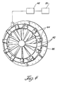
- FIG. 4 there is illustrated a plurality of adjustable inlet vanes 42 of the blower.
- Each of the vanes 42 are individually drive by motors 44.
- the motors 44 are circumferentially mounted on a circular support structure 46 in driving engagement with their associated vanes 42.
- the motors 44 are automatically controlled by a motor control circuit 48 which, in turn, is controlled by a controller 56.
- the controller 56 which is preferably programmable, also controls the operation of the drive system 36 as shown in Figure 2.
- control circuit 48 controls the operation of the motors 44. In this way the vanes 42 are moved between open and closed positions, thereby alternately allowing and restricting the flow of gas into the blower.
- Pressure and power requirements for tempering glass are hyperbolic functions of glass thickness as indicated in Figure 5.
- the pressure and power requirements in providing the quenching gas are functions of the inverse of the drive system.
- the drive system is preferably provided to minimize the power requirements in quenching thin glass such as thin architectural glass. By running the blower at full pressure and the drive system at substantially above its rated power output during quenching and reduced pressure during cooling the power requirements can be minimized by as much as 1/3.
- the size of the quench 14 is reduced to as small an area as possible to improve the planarity of the thin glass when produced on a lower production basis. Because the rated power requirement is less than the peak requirement, the blower drive and the blower motor of the blower are down-sized based on the duty cycle of the blower. In this way quench power is minimized and the plurality of the glass sheets is improved.
- FIG. 6 there is shown in graphic form the operation of the gas supply system for one period of a quench and cooling cycle wherein the blower is run intermittently and at different speeds rather than continuously.
- the blower speed increases from the start of the indicated period until quenching speed is achieved.
- the inlet vanes 42 are closed to minimize the gas horsepower required as shown in the second graph of Figure 6.
- the following table represents a hypothetical operation of the gas supply system including the blower to quench and cool four millimeter glass.
- the vanes 42 are held closed while the blower motor is accelerated to a quenching speed of approximately 1,016 rpm. Between times T2 and T3 the blower motor is held at this speed for approximately two seconds with the vanes 42 closed. Between times T3 and T4 the vanes 42 are open while the blower motor speed is maintained to allow the glass sheets to be quenched. After quenching, the power to the blower motor is removed and coasting occurs for a duration of approximately 14 seconds between times T4 and T5 in order to decelerate the blower motor. In order to stop the deceleration, power is applied to the blower motor for approximately one second in order to achieve the cooling speed between times T5 and T6. Between times T6 and T7, the cooling portion of the cooling period is entered which comprises one-half of the period.
- peak power requirements occur between times T1 and T2 and between times T5 and T6.
- This peak power level corresponds to the maximum rating of the blower drive and the blower drive motor.
- the switch gear, the blower motor and the blower drive is sized to the average power consumption or the rms average as shown in the last graph in Figure 6 during the quench cooling cycle.
- the quenching and cooling are carried out in a single quench unit 14, and a single blower and ductwork set is required.
- the glass sheets are allowed to enter into the quench unit 14 in a relatively rapid fashion (approximately 45.7 m/minute (150 feet per minute)) so that the entire piece of glass is quenched simultaneously, thereby resulting in a flatter piece of glass.
- the blower may also be operated to quench and cool relatively thick glass.
- the motor of the blower is decelerated from a cooling speed to a quench or heat strengthening speed as rapidly as possible after the motor has been accelerated from its quenching speed to its cooling speed.
- quenching and cooling of relatively thick glass can be obtained in a single quench unit by operating the blower on a duty cycle basis.
Landscapes
- Chemical & Material Sciences (AREA)
- Physics & Mathematics (AREA)
- Thermal Sciences (AREA)
- Engineering & Computer Science (AREA)
- Materials Engineering (AREA)
- Organic Chemistry (AREA)
- Re-Forming, After-Treatment, Cutting And Transporting Of Glass Products (AREA)
Description
- This invention relates to method and apparatus to improve glass sheet quenching and cooling and, in particular, to method and apparatus for supplying cooling air to improve glass sheet quenching and cooling.
- Glass sheets are quenched to provide tempering or heat strengthening in order to increase the mechanical strength of the glass and hence provide an increased resistance to breakage as compared to annealed glass. The sudden cooling process gives the glass sheets high compressive forces at their surfaces. Tempered glass sheets are less susceptible to breakage and break into small pieces that are dull and relatively harmless instead of into large pieces as in the case of untempered glass.
- In tempering, quenching gas is impinged with the opposite surfaces of the glass sheet to provide rapid cooling thereof such that the finally cooled glass sheet has compressive forces at its surfaces and tensile forces at its center.
- With heat strengthening, quenching gas is also impinged with the opposite surfaces of the glass sheet but at a much lower rate and thereby provides the surfaces of the glass with compressive forces but at a much lower level than is involved with tempering. Both tempering and heat strengthening can be performed on flat glass sheets such as are conveniently used for architectural purposes and on bent glass sheets such as are conveniently used for vehicle windows.
- Glass sheet quenches conventionally include opposed blastheads, each of which have elongated plenum housings or banks of nozzles that are spaced from each other and supply pressurized quenching gas to a heated glass sheet positioned between the blastheads. The plenums are spaced from each other to leave room for spent quenching gas to flow away from the glass sheet and between the plenums for flow out from between the blastheads. Normally, the quenching gas is supplied in discrete jets that are spaced along the length of each plenum housing as disclosed by US-A-3,936,291. Quenching jets are normally supplied in a parallel relationship to each other to provide tempering of flat glass sheets which are positioned between the opposed blastheads of the quench, extending in a perpendicular relationship to the quenching jets.
- In quenching glass sheets a greater amount of quenching gas must be supplied as the glass sheets become thinner than in the case with thicker glass sheets. The pressure and power requirements in supplying the quenching gas are hyperbolic functions of glass thickness. Consequently, as glass thickness decreases, the power, size and investment required for the air supply system for the quenching gas increases rapidly. This is especially true for batch-loaded oscillatory tempering systems with one or multiple load heating capacity.
- One possible solution to this increased need for quenching gas is to reduce the length of the device providing the quench to something less than the largest glass length and follow it by a full-length cooler. The glass may be passed through the quench at a rate sufficiently slow to impart the optimal degree of tempering and thereafter into the cooler where it oscillates until the next piece of glass is passed therethrough.
- This approach minimizes the length of the high-powered quenching unit and therefore the size and power requirements of the drive system of the blower as well. Further energy savings can be realized by shutting the quench unit off when a glass sheet is not present therein. However, there are mahy problems associated with this approach. For example, two sets of blowers and two sets of ductwork are required for each air supply system. Also, the low speed required for passing the glass sheet through the quench unit to ensure the proper degree of temper makes flatness control a problem, especially on wide sheets of glass. For example, when hot glass sheets move from the furnace into the quench unit, warpage and breakage tend to occur because the leading edge of the glass is being cooled and caused to shrink, while the trailing end is still hot and in its thermally expanded condition. This tendency is more severe, the slower the travel and the wider the glass.
- US-A-4004901 discloses a method for operating a gas supply system, and a gas supply system for a glass sheet quench according to the preamble of
claims 1 and 7 wherein the glass sheet quench has a quench cycle and a cooling cycle and wherein the system includes a drive system, a variable speed blower and opposed blastheads which are spaced from each other and supply pressurized gas from the blower to a heated glass sheet positioned between the blastheads. However in the present invention the drive system is operated on a duty cycle rather than on a continuous basis, and the peak power output of the drive system during the quenching cycle is greater than its rated power output to thereby reduce the initial and operating costs, and size and power requirements of the drive system. It is envisaged that in carrying out this object the glass sheet quench is able to quench and cool the glass sheets after receiving the glass sheets at a speed fast enough so that flatness control is not a significant problem and therein the size and power requirements of the drive system are minimized. - According to the present invention there is provided a method for operating a gas supply system for a glass sheet quench having a quench cycle and a cooling cycle, the system including a drive system of a variable speed blower and opposed blastheads which are spaced from each other and supply pressurized gas from the blower to a heated glass sheet (G) positioned between the blastheads, characterised by operating the blower at a first speed for a first length of time at substantially full power, causing the blower to slow down to a second speed for a second length of time, restricting the flow of gas to the blower while accelerating it to the first speed then allowing the gas to flow, and thereafter repeating the cycle.
- The present invention further provides a gas supply system for a glass sheet quench including a drive system of a variable speed blower and opposed blastheads which are spaced from each other and supply pressurized gas from the blower to a heated glass sheet (G) positioned between the blastheads, characterised in that the gas supply system further includes:
- restricting means for restricting gas flow from the blower; and
- control means for controlling the restricting means when changing the speed of the blower and then to permit increased flow of the pressurized gas, said control means also controlling the drive system to operate the blower at substantially full pressure at a first speed to supply pressurized gas for a first length of time, and for controlling the drive system to operate the blower at a pressure reduced from the full pressure at a second speed different from the first speed to supply pressurized gas for a second length of time.
- Normally, when operating with the glass, the first length of time will correspond to the quench cycle and the second length of time will be the cooling cycle. However, with thicker glass these cycles may be reversed.
- Preferably, the drive system is sized or rated so as to operate at substantially peak power well above its rated power during either the quench cycle or the cooling cycle. In this way savings of as much as 33% can be achieved.
- The objects, features and advantages of the present invention are readily apparent from the following detailed description of the best mode for carrying out the invention when taken in connection with the accompanying drawings.
-
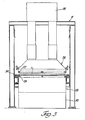
- Figure 1 is a schematic side elevation view of a glass tempering system including a gas supply system of quench constructed and operated in accordance with the present invention;
- Figure 2 is a top plan view of a glass tempering system including a gas supply system operated and constructed in accordance with the present invention;
- Figure 3 is an end view of the gas supply system of Figures 1 and 2;
- Figure 4 is a view of the vanes of the blower and associated control for the vanes;
- Figure 5 is a graph illustrating the pressure or power requirements for tempering glass as a function of glass thickness; and
- Figure 6 is a series of graphs, having the same time base, showing the interrelationship between the various components of the gas supply system and gas pressure or power.
- Referring to Figure 1 of the drawings, a glass tempering system, generally indicated at 10, includes a furnace 12 for heating glass sheets to a sufficiently high temperature for tempering. The system 10 also includes a
quench 14 having a gas supply system constructed and operated in accordance with the present invention to provide quenching that tempers the heated glass sheets and cooling as is hereinafter more fully described. - The furnace 12 is preferably of the type disclosed in US-A-3,934,970; 3,947,242; and 3,994,711 so as to include an
upper housing 16 and alower housing 18 that cooperatively define a side slot 20 at the opposite lateral sides of the furnace 12. - A
roller conveyor 22 of the furnace 12 includes conveyor rolls 24 whose opposite ends project outwardly through the furnace side slots 20 for frictional driving in the manner disclosed in the aforementioned patents. A flat glass sheet to be heated is introduced into the furnace 12 through an access opening at its left end and is conveyed within a suitably heated interior chamber by the conveyor rolls 24 for heating to a sufficiently high temperature (for example, between 649° and 704°C (1,200° to 1,300°F)) for subsequent tempering upon leaving the furnace 12 through an exit opening at its right end adjacent thequench 14. It should also be mentioned that thequench 14 can be utilized to provide heat strengthening of glass sheets by delivering a lower volume flow rate of quenching gas than that necessary to perform the tempering. - With combined reference to Figures 1 and 3, the
quench 14 includes upper and loweropposed blastheads nozzles - The
quench 14 also includes aroller conveyor 30 havingconveyor rolls 32 for conveying a heated glass sheet G between theblastheads nozzles roller conveyor 30 in a manner which is hereinafter more fully described. - The
quench unit 14 includes adrive system 36 of a fan or blower. The blower supplies quenching gas through upper andlower ducts drive system 36 comprises a variable speed blower motor, a transformer, a drive and switch gear sized or rated to the maximum gas pressure required for the thinnest glass to be quenched and cooled in thequench unit 14. - Referring now to Figure 4 there is illustrated a plurality of
adjustable inlet vanes 42 of the blower. Each of thevanes 42 are individually drive bymotors 44. Themotors 44 are circumferentially mounted on acircular support structure 46 in driving engagement with their associatedvanes 42. Themotors 44 are automatically controlled by amotor control circuit 48 which, in turn, is controlled by acontroller 56. Thecontroller 56, which is preferably programmable, also controls the operation of thedrive system 36 as shown in Figure 2. - Upon the receipt of proper control signals from the
controller 56, thecontrol circuit 48 controls the operation of themotors 44. In this way thevanes 42 are moved between open and closed positions, thereby alternately allowing and restricting the flow of gas into the blower. - Pressure and power requirements for tempering glass are hyperbolic functions of glass thickness as indicated in Figure 5. In other words, the pressure and power requirements in providing the quenching gas are functions of the inverse of the drive system. The drive system is preferably provided to minimize the power requirements in quenching thin glass such as thin architectural glass. By running the blower at full pressure and the drive system at substantially above its rated power output during quenching and reduced pressure during cooling the power requirements can be minimized by as much as 1/3. Also, by providing a single blower the size of the
quench 14 is reduced to as small an area as possible to improve the planarity of the thin glass when produced on a lower production basis. Because the rated power requirement is less than the peak requirement, the blower drive and the blower motor of the blower are down-sized based on the duty cycle of the blower. In this way quench power is minimized and the plurality of the glass sheets is improved. - Referring now to Figure 6 there is shown in graphic form the operation of the gas supply system for one period of a quench and cooling cycle wherein the blower is run intermittently and at different speeds rather than continuously. In the first graph if Figure 6 the blower speed increases from the start of the indicated period until quenching speed is achieved. In order to minimize acceleration time, the
inlet vanes 42 are closed to minimize the gas horsepower required as shown in the second graph of Figure 6. - The following table represents a hypothetical operation of the gas supply system including the blower to quench and cool four millimeter glass.

- In the above hypothetical, between times T1 and T2 as shown in Figure 6 the
vanes 42 are held closed while the blower motor is accelerated to a quenching speed of approximately 1,016 rpm. Between times T2 and T3 the blower motor is held at this speed for approximately two seconds with thevanes 42 closed. Between times T3 and T4 thevanes 42 are open while the blower motor speed is maintained to allow the glass sheets to be quenched. After quenching, the power to the blower motor is removed and coasting occurs for a duration of approximately 14 seconds between times T4 and T5 in order to decelerate the blower motor. In order to stop the deceleration, power is applied to the blower motor for approximately one second in order to achieve the cooling speed between times T5 and T6. Between times T6 and T7, the cooling portion of the cooling period is entered which comprises one-half of the period. - As shown in the table and the last graph of Figure 6, peak power requirements occur between times T1 and T2 and between times T5 and T6. This peak power level corresponds to the maximum rating of the blower drive and the blower drive motor. However, the switch gear, the blower motor and the blower drive is sized to the average power consumption or the rms average as shown in the last graph in Figure 6 during the quench cooling cycle.
- In the example shown for four millimeter glass, an average power of 98.4 kW (132 horsepower) is required. 223.7 kW (300 horsepower) is required during the quench portion of the period and 49.2 kW (66 horsepower) is required during the cooling portion of the cycle. A similar example for three millimeter glass will require 933.6 kW (1252 horsepower) during the quench portion of the cycle. However, if the blower is operated on a duty cycle basis, only a 596.6 kW (800 horsepower) drive and motor are required.
- The quenching and cooling are carried out in a single quench
unit 14, and a single blower and ductwork set is required. The glass sheets are allowed to enter into the quenchunit 14 in a relatively rapid fashion (approximately 45.7 m/minute (150 feet per minute)) so that the entire piece of glass is quenched simultaneously, thereby resulting in a flatter piece of glass. - The blower may also be operated to quench and cool relatively thick glass. In this situation the motor of the blower is decelerated from a cooling speed to a quench or heat strengthening speed as rapidly as possible after the motor has been accelerated from its quenching speed to its cooling speed. In this way quenching and cooling of relatively thick glass can be obtained in a single quench unit by operating the blower on a duty cycle basis.
- The following advantageous features follow from the present invention;
- (1) quenching and cooling are carried out in the same device;
- (2) only a single blower, drive system and ductwork set is required;
- (3) operating costs are lowered by minimizing energy usage;
- (4) the blower drive, motor, transformer and switch gear costs are minimized by as much as 1/3 in that they are sized to the rms requirements of the quench and cooling cycle; and
- (5) the glass is allowed to index into the quench
unit 14 relatively rapidly so that the whole glass piece is quenched simultaneously, thereby resulting in a flatter piece. - While a preferred embodiment of the subject invention has been shown and described herein in detail, those skilled in this art will recognize various alternative designs and embodiments for practicing the present invention as defined by the following claims.
Claims (9)
Priority Applications (1)
| Application Number | Priority Date | Filing Date | Title |
|---|---|---|---|
| AT84307593T ATE37859T1 (en) | 1983-11-14 | 1984-11-02 | METHOD AND DEVICE FOR SUPPLYING THE COOLING AIR TO A GLASS QUENCHING STATION. |
Applications Claiming Priority (2)
| Application Number | Priority Date | Filing Date | Title |
|---|---|---|---|
| US06/551,572 US4525193A (en) | 1983-11-14 | 1983-11-14 | Method and apparatus for supplying cooling air in a glass sheet quench |
| US551572 | 1983-11-14 |
Publications (2)
| Publication Number | Publication Date |
|---|---|
| EP0145246A1 EP0145246A1 (en) | 1985-06-19 |
| EP0145246B1 true EP0145246B1 (en) | 1988-10-12 |
Family
ID=24201815
Family Applications (1)
| Application Number | Title | Priority Date | Filing Date |
|---|---|---|---|
| EP84307593A Expired EP0145246B1 (en) | 1983-11-14 | 1984-11-02 | Method and apparatus for supplying cooling air in a glass sheet quench |
Country Status (17)
| Country | Link |
|---|---|
| US (1) | US4525193A (en) |
| EP (1) | EP0145246B1 (en) |
| JP (1) | JPS60127247A (en) |
| KR (1) | KR910009951B1 (en) |
| AR (1) | AR240665A1 (en) |
| AT (1) | ATE37859T1 (en) |
| AU (1) | AU567584B2 (en) |
| BR (1) | BR8405457A (en) |
| CA (1) | CA1212236A (en) |
| DE (1) | DE3474543D1 (en) |
| EG (1) | EG16898A (en) |
| ES (1) | ES537432A0 (en) |
| FI (1) | FI77635C (en) |
| IE (1) | IE56186B1 (en) |
| IN (1) | IN162775B (en) |
| NZ (1) | NZ209666A (en) |
| ZA (1) | ZA847415B (en) |
Families Citing this family (18)
| Publication number | Priority date | Publication date | Assignee | Title |
|---|---|---|---|---|
| JPS62158128A (en) * | 1985-12-27 | 1987-07-14 | Central Glass Co Ltd | Method for toughening thin glass pane |
| FI77216C (en) * | 1987-03-16 | 1989-02-10 | Kyro Oy | Control device for the blow pressure in a glass hardening device's cooling nozzles. |
| US4913720A (en) * | 1988-09-29 | 1990-04-03 | Glasstech, Inc. | Glass sheet modulated quenching |
| US5906668A (en) * | 1997-11-20 | 1999-05-25 | Glasstech, Inc. | Mold assembly for forming heated glass sheets |
| US5925162A (en) * | 1997-11-20 | 1999-07-20 | Glasstech, Inc. | Mold support assembly for heated glass sheet mold |
| US6729160B1 (en) | 1997-11-20 | 2004-05-04 | Glasstech, Inc. | Apparatus and method for forming heated glass sheets |
| US5917107A (en) * | 1997-11-20 | 1999-06-29 | Glasstech, Inc. | Quench loader for installing glass sheet quench module set |
| US5900034A (en) * | 1997-11-20 | 1999-05-04 | Glasstech, Inc. | Support and actuating mechanism for mold support assembly used for heated glass sheet forming |
| US6032491A (en) * | 1997-11-20 | 2000-03-07 | Glasstech, Inc. | Apparatus for mold changing in heated glass sheet forming station |
| KR100370928B1 (en) * | 2002-06-19 | 2003-02-07 | 유병섭 | A cooling device of strengthened glass manufacture system |
| US7958750B2 (en) * | 2005-10-21 | 2011-06-14 | Glasstech, Inc. | Glass sheet forming system |
| US8074473B2 (en) * | 2006-12-01 | 2011-12-13 | Glasstech, Inc. | Method for quenching formed glass sheets |
| US7716949B2 (en) * | 2007-04-04 | 2010-05-18 | Glasstech, Inc. | Method for positioning glass sheets for forming |
| JP5428288B2 (en) * | 2007-12-25 | 2014-02-26 | 日本電気硝子株式会社 | Glass plate manufacturing method and manufacturing equipment |
| US9611166B2 (en) | 2014-10-02 | 2017-04-04 | Glasstech, Inc. | Glass quench apparatus |
| US9758421B2 (en) | 2015-11-02 | 2017-09-12 | Glasstech, Inc. | Glass sheet processing system having cooling of conveyor roller ends |
| JP6691965B2 (en) | 2015-11-02 | 2020-05-13 | グラステク インコーポレイテッド | Glass plate forming system |
| US9745147B2 (en) | 2015-11-02 | 2017-08-29 | Glasstech, Inc. | Glass sheet forming system |
Family Cites Families (6)
| Publication number | Priority date | Publication date | Assignee | Title |
|---|---|---|---|---|
| IE35468B1 (en) * | 1970-07-29 | 1976-02-18 | Triplex Safety Glass Co | Improvements in or relating to toughened glass sheets |
| CA998244A (en) * | 1972-08-14 | 1976-10-12 | Harold A. Mcmaster | Glass tempering blasthead |
| US3923488A (en) * | 1974-04-26 | 1975-12-02 | Ppg Industries Inc | Method of tempering flat glass sheets |
| US3947242A (en) * | 1975-02-19 | 1976-03-30 | Mcmaster Harold | Roller hearth furnace for glass sheets |
| US3994711A (en) * | 1975-09-15 | 1976-11-30 | Mcmaster Harold | Glass tempering system including oscillating roller furnace |
| US4004901A (en) * | 1975-10-28 | 1977-01-25 | Ppg Industries, Inc. | Tempering glass sheets |
-
1983
- 1983-11-14 US US06/551,572 patent/US4525193A/en not_active Expired - Lifetime
-
1984
- 1984-09-17 CA CA000463276A patent/CA1212236A/en not_active Expired
- 1984-09-18 IE IE2372/84A patent/IE56186B1/en unknown
- 1984-09-20 ZA ZA847415A patent/ZA847415B/en unknown
- 1984-09-24 NZ NZ209666A patent/NZ209666A/en unknown
- 1984-09-28 AU AU33664/84A patent/AU567584B2/en not_active Ceased
- 1984-10-17 JP JP59218179A patent/JPS60127247A/en active Granted
- 1984-10-18 IN IN786/MAS/84A patent/IN162775B/en unknown
- 1984-10-24 AR AR29836184A patent/AR240665A1/en active
- 1984-10-26 KR KR1019840006667A patent/KR910009951B1/en not_active Expired
- 1984-10-26 BR BR8405457A patent/BR8405457A/en not_active IP Right Cessation
- 1984-11-02 DE DE8484307593T patent/DE3474543D1/en not_active Expired
- 1984-11-02 AT AT84307593T patent/ATE37859T1/en not_active IP Right Cessation
- 1984-11-02 EP EP84307593A patent/EP0145246B1/en not_active Expired
- 1984-11-07 ES ES537432A patent/ES537432A0/en active Granted
- 1984-11-13 EG EG700/84A patent/EG16898A/en active
- 1984-11-13 FI FI844454A patent/FI77635C/en not_active IP Right Cessation
Also Published As
| Publication number | Publication date |
|---|---|
| FI844454A0 (en) | 1984-11-13 |
| DE3474543D1 (en) | 1988-11-17 |
| EP0145246A1 (en) | 1985-06-19 |
| US4525193A (en) | 1985-06-25 |
| AU567584B2 (en) | 1987-11-26 |
| FI77635B (en) | 1988-12-30 |
| BR8405457A (en) | 1985-09-03 |
| ZA847415B (en) | 1985-04-24 |
| IE56186B1 (en) | 1991-05-08 |
| EG16898A (en) | 1991-08-30 |
| KR910009951B1 (en) | 1991-12-07 |
| ES8601074A1 (en) | 1985-10-16 |
| ATE37859T1 (en) | 1988-10-15 |
| NZ209666A (en) | 1986-06-11 |
| KR850004734A (en) | 1985-07-27 |
| IN162775B (en) | 1988-07-09 |
| AU3366484A (en) | 1985-05-23 |
| JPS6247820B2 (en) | 1987-10-09 |
| IE842372L (en) | 1985-05-14 |
| AR240665A1 (en) | 1990-08-31 |
| CA1212236A (en) | 1986-10-07 |
| ES537432A0 (en) | 1985-10-16 |
| FI77635C (en) | 1989-04-10 |
| JPS60127247A (en) | 1985-07-06 |
| FI844454L (en) | 1985-05-15 |
Similar Documents
| Publication | Publication Date | Title |
|---|---|---|
| EP0145246B1 (en) | Method and apparatus for supplying cooling air in a glass sheet quench | |
| EP0010854B1 (en) | Process for heat treating moving glass sheets on a modified gas bed | |
| EP0721922A1 (en) | Method for heating glass sheets to be tempered or heat-strengthened | |
| DE69702982D1 (en) | OVEN FOR THE HEAT TREATMENT OF GLASS PANELS | |
| GB2365862A (en) | Method and apparatus for making a curved glass-ceramic panel by bending a glass panel to be ceramicized | |
| FI101621B (en) | Method for heat-soak treatment of cured glass sheets | |
| EP0000269B1 (en) | Method for thermally toughening glass sheets and glass sheets obtained by this method, in particular to be used as motor vehicle side or rear windows. | |
| CN105693071A (en) | Air floatation device for glass heating | |
| CN105621874B (en) | Methods for tempering glass sheets | |
| CN107502724A (en) | Bolt heat treatment system and method | |
| CN112939434B (en) | Tempering furnace for glass production | |
| CN201933107U (en) | Isothermal annealing device utilizing tooth billet forging residual heat | |
| CN110498598B (en) | Semi-tempered glass cooling system capable of improving productivity and semi-tempered glass production process | |
| US4886540A (en) | Blow back control device for a glass sheet tempering system | |
| JP2008512333A (en) | Method and apparatus for heating glass sheet | |
| GB2045593A (en) | Bakers oven | |
| EP4008693B1 (en) | Wind outlet structure and cooling device | |
| JP2003154408A (en) | Gradient heating method for billet and batchwise gradient heater for billet | |
| CN219347201U (en) | Drying device | |
| CN208776783U (en) | A kind of automatic solid solution production line | |
| US4311507A (en) | Special entrance slit module and method for quenching glass sheets | |
| CN219546877U (en) | Quick cooling device is used in toughened glass processing | |
| CN210287134U (en) | Glass tempering furnace | |
| JP4012993B2 (en) | Sheet glass bending apparatus and method | |
| CN222844548U (en) | A plate air-cooling shaping machine with adjustment function |
Legal Events
| Date | Code | Title | Description |
|---|---|---|---|
| PUAI | Public reference made under article 153(3) epc to a published international application that has entered the european phase |
Free format text: ORIGINAL CODE: 0009012 |
|
| AK | Designated contracting states |
Designated state(s): AT BE CH DE FR GB IT LI LU NL SE |
|
| 17P | Request for examination filed |
Effective date: 19851204 |
|
| 17Q | First examination report despatched |
Effective date: 19860818 |
|
| GRAA | (expected) grant |
Free format text: ORIGINAL CODE: 0009210 |
|
| AK | Designated contracting states |
Kind code of ref document: B1 Designated state(s): AT BE CH DE FR GB IT LI LU NL SE |
|
| PG25 | Lapsed in a contracting state [announced via postgrant information from national office to epo] |
Ref country code: CH Effective date: 19881012 Ref country code: NL Effective date: 19881012 Ref country code: AT Effective date: 19881012 Ref country code: LI Effective date: 19881012 Ref country code: SE Effective date: 19881012 |
|
| REF | Corresponds to: |
Ref document number: 37859 Country of ref document: AT Date of ref document: 19881015 Kind code of ref document: T |
|
| REF | Corresponds to: |
Ref document number: 3474543 Country of ref document: DE Date of ref document: 19881117 |
|
| PGFP | Annual fee paid to national office [announced via postgrant information from national office to epo] |
Ref country code: AT Payment date: 19881123 Year of fee payment: 5 |
|
| PGFP | Annual fee paid to national office [announced via postgrant information from national office to epo] |
Ref country code: NL Payment date: 19881130 Year of fee payment: 5 |
|
| REG | Reference to a national code |
Ref country code: CH Ref legal event code: PL |
|
| EN | Fr: translation not filed | ||
| NLV1 | Nl: lapsed or annulled due to failure to fulfill the requirements of art. 29p and 29m of the patents act | ||
| ITF | It: translation for a ep patent filed | ||
| PLBE | No opposition filed within time limit |
Free format text: ORIGINAL CODE: 0009261 |
|
| STAA | Information on the status of an ep patent application or granted ep patent |
Free format text: STATUS: NO OPPOSITION FILED WITHIN TIME LIMIT |
|
| 26N | No opposition filed | ||
| ET | Fr: translation filed | ||
| REG | Reference to a national code |
Ref country code: FR Ref legal event code: BR |
|
| ITTA | It: last paid annual fee | ||
| PGFP | Annual fee paid to national office [announced via postgrant information from national office to epo] |
Ref country code: LU Payment date: 19931001 Year of fee payment: 10 |
|
| PGFP | Annual fee paid to national office [announced via postgrant information from national office to epo] |
Ref country code: GB Payment date: 19931011 Year of fee payment: 10 |
|
| PGFP | Annual fee paid to national office [announced via postgrant information from national office to epo] |
Ref country code: FR Payment date: 19931110 Year of fee payment: 10 |
|
| PGFP | Annual fee paid to national office [announced via postgrant information from national office to epo] |
Ref country code: DE Payment date: 19931126 Year of fee payment: 10 |
|
| PGFP | Annual fee paid to national office [announced via postgrant information from national office to epo] |
Ref country code: BE Payment date: 19931210 Year of fee payment: 10 |
|
| EPTA | Lu: last paid annual fee | ||
| PG25 | Lapsed in a contracting state [announced via postgrant information from national office to epo] |
Ref country code: GB Effective date: 19941102 Ref country code: LU Free format text: LAPSE BECAUSE OF NON-PAYMENT OF DUE FEES Effective date: 19941102 |
|
| PG25 | Lapsed in a contracting state [announced via postgrant information from national office to epo] |
Ref country code: BE Effective date: 19941130 |
|
| BERE | Be: lapsed |
Owner name: GLASSTECH INC. Effective date: 19941130 |
|
| GBPC | Gb: european patent ceased through non-payment of renewal fee |
Effective date: 19941102 |
|
| PG25 | Lapsed in a contracting state [announced via postgrant information from national office to epo] |
Ref country code: DE Effective date: 19950801 |
|
| PG25 | Lapsed in a contracting state [announced via postgrant information from national office to epo] |
Ref country code: FR Effective date: 19950831 |
|
| REG | Reference to a national code |
Ref country code: FR Ref legal event code: ST |
|
| PG25 | Lapsed in a contracting state [announced via postgrant information from national office to epo] |
Ref country code: FR Effective date: 19941130 |