EP0145196B1 - Verfahren zur Reparatur von Kokillen - Google Patents
Verfahren zur Reparatur von Kokillen Download PDFInfo
- Publication number
- EP0145196B1 EP0145196B1 EP84307327A EP84307327A EP0145196B1 EP 0145196 B1 EP0145196 B1 EP 0145196B1 EP 84307327 A EP84307327 A EP 84307327A EP 84307327 A EP84307327 A EP 84307327A EP 0145196 B1 EP0145196 B1 EP 0145196B1
- Authority
- EP
- European Patent Office
- Prior art keywords
- cast iron
- cavity
- mould
- deposit
- iron
- Prior art date
- Legal status (The legal status is an assumption and is not a legal conclusion. Google has not performed a legal analysis and makes no representation as to the accuracy of the status listed.)
- Expired
Links
- 238000000034 method Methods 0.000 title claims abstract description 23
- 229910001018 Cast iron Inorganic materials 0.000 claims abstract description 48
- 229910001060 Gray iron Inorganic materials 0.000 claims abstract description 17
- 238000001816 cooling Methods 0.000 claims abstract description 12
- 238000010891 electric arc Methods 0.000 claims abstract description 11
- XEEYBQQBJWHFJM-UHFFFAOYSA-N Iron Chemical compound [Fe] XEEYBQQBJWHFJM-UHFFFAOYSA-N 0.000 claims description 44
- OKTJSMMVPCPJKN-UHFFFAOYSA-N Carbon Chemical compound [C] OKTJSMMVPCPJKN-UHFFFAOYSA-N 0.000 claims description 28
- 238000003466 welding Methods 0.000 claims description 23
- 229910052742 iron Inorganic materials 0.000 claims description 21
- 229910052799 carbon Inorganic materials 0.000 claims description 17
- 229910002804 graphite Inorganic materials 0.000 claims description 10
- 239000010439 graphite Substances 0.000 claims description 10
- 238000011109 contamination Methods 0.000 claims description 3
- 230000008021 deposition Effects 0.000 claims description 2
- 229910052751 metal Inorganic materials 0.000 description 14
- 239000002184 metal Substances 0.000 description 14
- 229910000831 Steel Inorganic materials 0.000 description 9
- 239000010959 steel Substances 0.000 description 9
- 230000000694 effects Effects 0.000 description 7
- 238000000151 deposition Methods 0.000 description 5
- 239000000203 mixture Substances 0.000 description 5
- 229910001209 Low-carbon steel Inorganic materials 0.000 description 3
- 239000010953 base metal Substances 0.000 description 3
- 239000000945 filler Substances 0.000 description 3
- 239000000463 material Substances 0.000 description 3
- RYGMFSIKBFXOCR-UHFFFAOYSA-N Copper Chemical compound [Cu] RYGMFSIKBFXOCR-UHFFFAOYSA-N 0.000 description 2
- UQSXHKLRYXJYBZ-UHFFFAOYSA-N Iron oxide Chemical compound [Fe]=O UQSXHKLRYXJYBZ-UHFFFAOYSA-N 0.000 description 2
- 229910052802 copper Inorganic materials 0.000 description 2
- 239000010949 copper Substances 0.000 description 2
- 238000004519 manufacturing process Methods 0.000 description 2
- 229910001562 pearlite Inorganic materials 0.000 description 2
- 229910052710 silicon Inorganic materials 0.000 description 2
- 239000010703 silicon Substances 0.000 description 2
- 238000012546 transfer Methods 0.000 description 2
- 230000009466 transformation Effects 0.000 description 2
- 241000271510 Agkistrodon contortrix Species 0.000 description 1
- 229910001339 C alloy Inorganic materials 0.000 description 1
- 229910000640 Fe alloy Inorganic materials 0.000 description 1
- 229910000676 Si alloy Inorganic materials 0.000 description 1
- XUIMIQQOPSSXEZ-UHFFFAOYSA-N Silicon Chemical compound [Si] XUIMIQQOPSSXEZ-UHFFFAOYSA-N 0.000 description 1
- 229910052782 aluminium Inorganic materials 0.000 description 1
- XAGFODPZIPBFFR-UHFFFAOYSA-N aluminium Chemical compound [Al] XAGFODPZIPBFFR-UHFFFAOYSA-N 0.000 description 1
- 238000000137 annealing Methods 0.000 description 1
- 230000009286 beneficial effect Effects 0.000 description 1
- 238000005266 casting Methods 0.000 description 1
- 229910001567 cementite Inorganic materials 0.000 description 1
- 238000006243 chemical reaction Methods 0.000 description 1
- 238000010276 construction Methods 0.000 description 1
- 230000008602 contraction Effects 0.000 description 1
- 238000007796 conventional method Methods 0.000 description 1
- 238000005336 cracking Methods 0.000 description 1
- 230000002950 deficient Effects 0.000 description 1
- 239000003517 fume Substances 0.000 description 1
- 230000004927 fusion Effects 0.000 description 1
- 239000007789 gas Substances 0.000 description 1
- 230000005484 gravity Effects 0.000 description 1
- 238000010438 heat treatment Methods 0.000 description 1
- BHEPBYXIRTUNPN-UHFFFAOYSA-N hydridophosphorus(.) (triplet) Chemical compound [PH] BHEPBYXIRTUNPN-UHFFFAOYSA-N 0.000 description 1
- KSOKAHYVTMZFBJ-UHFFFAOYSA-N iron;methane Chemical compound C.[Fe].[Fe].[Fe] KSOKAHYVTMZFBJ-UHFFFAOYSA-N 0.000 description 1
- 230000007246 mechanism Effects 0.000 description 1
- 150000001247 metal acetylides Chemical class 0.000 description 1
- 238000000465 moulding Methods 0.000 description 1
- 230000003647 oxidation Effects 0.000 description 1
- 238000007254 oxidation reaction Methods 0.000 description 1
- 239000012256 powdered iron Substances 0.000 description 1
- 230000002028 premature Effects 0.000 description 1
- 230000002265 prevention Effects 0.000 description 1
- 238000012545 processing Methods 0.000 description 1
- 238000003303 reheating Methods 0.000 description 1
- 239000002893 slag Substances 0.000 description 1
- 239000000779 smoke Substances 0.000 description 1
- 238000007711 solidification Methods 0.000 description 1
- 230000008023 solidification Effects 0.000 description 1
- 238000010561 standard procedure Methods 0.000 description 1
- 239000002436 steel type Substances 0.000 description 1
- 238000009628 steelmaking Methods 0.000 description 1
- 239000003832 thermite Substances 0.000 description 1
- 238000003886 thermite process Methods 0.000 description 1
Images
Classifications
-
- B—PERFORMING OPERATIONS; TRANSPORTING
- B22—CASTING; POWDER METALLURGY
- B22D—CASTING OF METALS; CASTING OF OTHER SUBSTANCES BY THE SAME PROCESSES OR DEVICES
- B22D7/00—Casting ingots, e.g. from ferrous metals
- B22D7/06—Ingot moulds or their manufacture
-
- B—PERFORMING OPERATIONS; TRANSPORTING
- B22—CASTING; POWDER METALLURGY
- B22D—CASTING OF METALS; CASTING OF OTHER SUBSTANCES BY THE SAME PROCESSES OR DEVICES
- B22D7/00—Casting ingots, e.g. from ferrous metals
- B22D7/06—Ingot moulds or their manufacture
- B22D7/066—Manufacturing, repairing or reinforcing ingot moulds
-
- B—PERFORMING OPERATIONS; TRANSPORTING
- B23—MACHINE TOOLS; METAL-WORKING NOT OTHERWISE PROVIDED FOR
- B23K—SOLDERING OR UNSOLDERING; WELDING; CLADDING OR PLATING BY SOLDERING OR WELDING; CUTTING BY APPLYING HEAT LOCALLY, e.g. FLAME CUTTING; WORKING BY LASER BEAM
- B23K9/00—Arc welding or cutting
- B23K9/04—Welding for other purposes than joining, e.g. built-up welding
-
- B—PERFORMING OPERATIONS; TRANSPORTING
- B23—MACHINE TOOLS; METAL-WORKING NOT OTHERWISE PROVIDED FOR
- B23K—SOLDERING OR UNSOLDERING; WELDING; CLADDING OR PLATING BY SOLDERING OR WELDING; CUTTING BY APPLYING HEAT LOCALLY, e.g. FLAME CUTTING; WORKING BY LASER BEAM
- B23K9/00—Arc welding or cutting
- B23K9/12—Automatic feeding or moving of electrodes or work for spot or seam welding or cutting
- B23K9/121—Devices for the automatic supply of at least two electrodes one after the other
Definitions
- This invention relates to a method of rebuilding and/or repairing grey cast iron ingot moulds which, through use, have developed cavities, by filling the cavities with cast iron by means of electric arc welding technique, using a manually held welding head.
- Tubular welding wire as referred to herein, is a continuous tubular sheath containing a filler composition, which in combination yield a weld deposit of graphitic cast iron structure when applied by electric arc welding technique.
- tubular welding wire with a sheath and core composition
- cores are usually powdered and the tubular wires are flexible for feed purposes from a reel or the like.
- molten steel from furnaces is poured into ingot moulds.
- These moulds are made from grey cast iron which is chosen because of its good heat transfer properties. This aspect of grey cast iron is largely due to the presence of contained carbon as free graphite. This free graphite has a low specific gravity relative to iron and may occupy up to 17% of the total iron volume.
- the steel-pouring process erodes cavities in the moulds and stools at critical locations. These cavities produce ingots with appendages on the sides and/or ends which result in increased costs when further processing the ingot.
- the cavities reach a size where either the cavity must be repaired or the mould or stool must be scrapped for reasons of economy and prevention of molten metal run-outs.
- the cost of replacing moulds or stools is a significant cost in steel manufacturing and mould and stool repair is an endeavour to which considerable attention is being directed.
- Some present practise is to scarf and/or grind the defective area of the mould to improve useful life and ingot quality.
- Another current practise is to repair cavities using a bare cast iron filler rod and mild steel electrode by electric arc welding.
- the mild steel electrode is used as the heat source as well as depositing mild steel metal, while the bare cast iron rod is hand fed into the arc and molten pool, resulting in a chilled semi-steel structure. This process is slow, involves a non-continuous deposit, slag producing and costly.
- Another practice is to use a bare cast iron electrode in electric welding, which produces a substantially chilled iron structure. Complete fusion of weld is difficult to achieve using this method, it is a non-continuous deposit, costly, slow and produces a very hard and brittle weld structure.
- a thermite method of filling the cavity has been used with some success. This involves the deposit of a powdered iron oxide and aluminum mixture into the cavity, igniting it to cause a sudden chemical reaction that releases excessive heat and leaves a filling deposit that is fused into the cavity.
- a disadvantage of the thermite process is that it emits an objectionable amount of smoke and obnoxious fumes.
- the resultant weld structure is usually of the semi-steel type.
- An ideal cavity repair material should be similar in chemistry and structure to the base metal of the mould or stool. Coefficient of expansion characteristics and thermal conductivity of the weld metal should be similar to the cast iron of the mould or stool. It is important that the material used to fill the cavity should be readily grindable because after the cavity is filled, the repair area must be ground to make it conform to the required surface of the mould or stool. It is also desirable that the filling material should have heat-flow, expansion and contraction characteristics similar to the grey cast iron of the mould or stool. Current practises fall short of ideal compatibility, because the heat transfer of ingot mould iron and the massive heat sink from the mass of the mould causes weld metal of suitable analysis deposited in the cavity to cool so rapidly that a chilled metal structure results, wherein most carbon is chemically combined.
- a method of rebuilding and/or repairing a grey cast iron ingot mould having a cavity eroded in the graphitic cast iron therefore by filling the cavity with cast iron by electric arc deposit using a manually held welding head is characterized by: feeding the iron from more than one continuous tubular welding supply at a current density and deposition rate to burn off contamination on the cavity wall, to fuse the deposit to the mould and to heat the cast iron pool created by the arc deposit to an extent that provides a cooling time long enough to permit substantial amounts of the carbon to precipitate out as graphite whereby on cooling the whole cavity is filled with substantially graphitic cast iron.
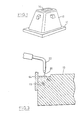
- Figure 1 illustrates, schematically, an ingot mould assembly which includes a base or stool 10, and a mould 12.
- molten metal is poured into the hole 14, in the top of the mould to fill the mould, and permitted to solidify. After solidification, the mould is lifted from the base and the steel ingot is removed. The mould is then reused to form further ingots. This process is well known.
- This invention utilizes multiple tubular wire electrodes fed from a motor drive through wire guide cables to the output heads of an electric arc welding machine, such that all wire feed rates are controlled to provide sufficient weld metal and sufficient heat to the cavity to heat the mould and create a pool of molten cast iron that has sufficient heat therein so that it cools over a time period long enough for graphitic cast iron to form in the cavity, this deposit being fused to the cast iron of the mould.
- sufficient heat can be supplied to the molten metal deposited in the cavity and surrounding area, from the arc of the output of the welder to retard the cooling rate of the weld deposit iron enough to permit carbon to precipitate as graphite whereby the cavity is filled with substantially graphitic iron that is compatible with the grey iron of the body of the mould.
- the invention achieves sufficient heat producing energy through controlled current density at the arc and wire feed rate.
- Suitable preheat and post heat can be used as assists, depending on conditions, and wire chemistry is selected to do the job.
- the surface of the cavity will often be contaminated with oxidation or graphite, which is difficult to weld using conventional techniques. With this invention this contamination is burned off with the extremely high current density of the arc and by correctly manipulating the arc. The oxide deposit is displaced, and the graphite is dissolved or consumed in the arc and/or pool.
- the density in the current of the arc in the case of the three wire deposit is nearly nine times the arc density of the case of the deposit from the single rod. This results in a dramatic increase in the amount of heat energy generated at the location of the deposit. This is reflected also in the power supplied through the arc. It will further be noted that the deposit rate the case of the three wire deposit is nearly five times the deposit rate as in the case of the single rod deposit.
- the increased heating effect derived from the current density increase in the arc, and from the rate of deposit increase, is sufficient to overcome the chilling effect of the mould and to result in a substantially graphitic cast iron deposit in the cavity fused to the old cavity wall. As indicated, the cavity was one of approx. 8200 cubic centimetres (or 500 cubic inches).
- the resulting cooled deposit will be substantially graphitic iron but there may well be some chilled cast iron involved in the deposit or close to the original surface of the cavity in the mould. It is likely that in some applications iron just below the surface of the original cavity surface will be chilled and form a hard cast iron because the heat supplied by the arc is not great enough to fully overcome the chilling effect of the mass of the mould at this location. Moreover, it is not inconceivable that there may be some chilled iron in the deposit close to the surface of the original cavity. It is a matter of degree, the faster the cooling rate the greater the amount of chilled iron. Conditions need not be such that all chilled iron is eliminated from the deposited ore body or from the mass of the original mould. They only need be such that by and large the greater part of the deposit is graphitic iron. The substantial part of the deposit is substantially graphitic iron and has a hardness under 300 Brinnel.
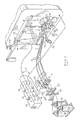
- Figure 2 is a schematic illustration of a machine for filling cavities in ingot moulds according to this invention.
- the technical specification of the individual outputs of the machine is standard for arc welding.
- the machine has a head 20, with three outputs 22, 24, and 26 spaced about 2.5 cm [1"] apart in a straight line.
- the head and outputs are of common construction and comprise a copper head with copper tube outputs extending therefrom.
- Cast iron electrode wires 28, 30, and 32 are fed from spools 34, 36, and 38, respectively through wire roller guides 40, and 42, by means of pairs of driven co-operating knurlled rollers generally indicated by the numeral 43.
- the wires After the wires pass through the supply rolls 43, they travel through flexible wire guide cables generally indicated by the numeral 44 to the copper feedhead 20.
- the power supplies 46, 48, and 50, to the outputs 22, 24, and 26, of the head 20 is through current cables generally indicated by the numeral 52.
- the head 20 is manipulated by the operator's handle 54; the head is suspended from a track 56 that can be rotated about mounting post 58. The tract pivots about the mounting post and it will be apparent that by manipulation of the handle 54, the head 20 can be moved universally within its mounting. Vertical movement is by means of adjustment in the vertical shaft or by fulcrum movement.
- Numeral 62 is a control cable available to the operator at the handle 54 that transmits control information back to the wire feed motor 66, and control 68.
- the operator sets the controls on his welding machines according to standard procedure, sets the rate of feed 68, for the drive rollers 43 to achieve the desired feed rate of the wire to the welding head 20.
- the rate of feed is the same and continuous for each of the wires. Specific rates will depend on the job to be done and determined by the skill of the operator, having regard to the requirement to supply heat to the mould and deposit from the arc to heat the cast iron pool to an extent that the pool provides a cooling time long enough to permit substantial amounts of the carbon therein to precipitate out as graphite whereby on cooling the cavity is filled with substantially graphitic cast iron.
- a cavity in the side of the mould has been described because this is the most common cavity dealt with in steel ingot moulding practice. Cavities occur also at other places such as the centre of the stool. They are all repairable by this process.
- the tubular wires can be supplied continuously from suitable reels or drums or other feed mechanisms to the one illustrated so as to permit a non-interrupted welding cycle.
- the cavity is, if necessary, dammed with a refractory dam 64, in order to maintain the pool as the cavity is filled.
- the operator applies molten cast iron by arc deposit to the bottom of the cavity and works across the mould until a body that fills the cavity is deposited.
- Gas shielding in certain instances may prove beneficial but is not deemed essential to the process. This is a matter of general welding technique known to those skilled in the welding art.
- the top portion of the mould has been illustrated.
- the stools also develop cavities and it is intended that stools be included in the general term ingot moulds.
Landscapes
- Engineering & Computer Science (AREA)
- Mechanical Engineering (AREA)
- Physics & Mathematics (AREA)
- Plasma & Fusion (AREA)
- Manufacturing & Machinery (AREA)
- Arc Welding In General (AREA)
- Nonmetallic Welding Materials (AREA)
- Moulds For Moulding Plastics Or The Like (AREA)
- Forging (AREA)
Claims (2)
Priority Applications (1)
| Application Number | Priority Date | Filing Date | Title |
|---|---|---|---|
| AT84307327T ATE32189T1 (de) | 1983-11-16 | 1984-10-24 | Verfahren zur reparatur von kokillen. |
Applications Claiming Priority (2)
| Application Number | Priority Date | Filing Date | Title |
|---|---|---|---|
| CA000441255A CA1215129A (en) | 1983-11-16 | 1983-11-16 | Ingot mould repair method |
| CA441255 | 1983-11-16 |
Publications (2)
| Publication Number | Publication Date |
|---|---|
| EP0145196A1 EP0145196A1 (de) | 1985-06-19 |
| EP0145196B1 true EP0145196B1 (de) | 1988-01-27 |
Family
ID=4126534
Family Applications (1)
| Application Number | Title | Priority Date | Filing Date |
|---|---|---|---|
| EP84307327A Expired EP0145196B1 (de) | 1983-11-16 | 1984-10-24 | Verfahren zur Reparatur von Kokillen |
Country Status (4)
| Country | Link |
|---|---|
| EP (1) | EP0145196B1 (de) |
| AT (1) | ATE32189T1 (de) |
| CA (1) | CA1215129A (de) |
| DE (1) | DE3468989D1 (de) |
Cited By (1)
| Publication number | Priority date | Publication date | Assignee | Title |
|---|---|---|---|---|
| WO2019164731A3 (en) * | 2018-02-22 | 2020-04-30 | E. Holdings, Inc. | Method for making mg brass edm wire |
Families Citing this family (1)
| Publication number | Priority date | Publication date | Assignee | Title |
|---|---|---|---|---|
| EP0580703B1 (de) * | 1991-04-18 | 1997-11-05 | KOSTECKI, Gene | Überlappende bleche |
Family Cites Families (3)
| Publication number | Priority date | Publication date | Assignee | Title |
|---|---|---|---|---|
| US2151914A (en) * | 1936-09-16 | 1939-03-28 | Kellogg M W Co | Welding apparatus |
| AT210073B (de) * | 1958-10-27 | 1960-07-11 | Giovanni Galvani | Verfahren zum Ausbessern von Blockgießformen, Gießplatten u. dgl. |
| DE6930834U (de) * | 1969-08-04 | 1971-05-13 | Hilti Ag | Reparierte kokille. |
-
1983
- 1983-11-16 CA CA000441255A patent/CA1215129A/en not_active Expired
-
1984
- 1984-10-24 DE DE8484307327T patent/DE3468989D1/de not_active Expired
- 1984-10-24 EP EP84307327A patent/EP0145196B1/de not_active Expired
- 1984-10-24 AT AT84307327T patent/ATE32189T1/de not_active IP Right Cessation
Non-Patent Citations (1)
| Title |
|---|
| "WELDING JOURNAL" A.G. Hogaboom, Vol. 56, No. 7 (1977 02) "WELDING OF GRAY CAST IRON" * |
Cited By (2)
| Publication number | Priority date | Publication date | Assignee | Title |
|---|---|---|---|---|
| WO2019164731A3 (en) * | 2018-02-22 | 2020-04-30 | E. Holdings, Inc. | Method for making mg brass edm wire |
| US10780476B2 (en) | 2018-02-22 | 2020-09-22 | E. Holdings, Inc | Method for making Mg brass EDM wire |
Also Published As
| Publication number | Publication date |
|---|---|
| EP0145196A1 (de) | 1985-06-19 |
| CA1215129A (en) | 1986-12-09 |
| DE3468989D1 (en) | 1988-03-03 |
| ATE32189T1 (de) | 1988-02-15 |
Similar Documents
| Publication | Publication Date | Title |
|---|---|---|
| US9545665B2 (en) | Method of repairing defects in cast iron workpieces, and a method of connecting cast iron workpieces | |
| US3308266A (en) | Method and apparatus for welding of rails | |
| US3650311A (en) | Method for homogeneous refining and continuously casting metals and alloys | |
| GB2112313A (en) | Method for welding railroad rails and means therefor | |
| US3625757A (en) | Coated consumable guide tube for electroslag welding | |
| US3469968A (en) | Electroslag melting | |
| US4207454A (en) | Method for electroslag welding of metals | |
| US4413169A (en) | Electro-slag welding process for irregular sections | |
| EP0145196B1 (de) | Verfahren zur Reparatur von Kokillen | |
| US4593747A (en) | Ingot mould repair method | |
| CA1234476A (en) | Method and device for production of metal blocks, castings or profile material with enclosed hard metal grains | |
| US2248628A (en) | Method of casting metal bodies | |
| US4132545A (en) | Method of electroslag remelting processes using a preheated electrode shield | |
| JP2021501834A (ja) | 同時に回転可能かつ移動可能な電極ロッドを備えた溶解炉 | |
| CN113798474A (zh) | 一种电渣增材制造方法 | |
| RU2039101C1 (ru) | Способ электрошлаковой выплавки ферротитана | |
| US4192370A (en) | Device for effecting electroslag remelting processes | |
| GB1420709A (en) | Method of repairing heavy iron articles especially ingot stools and ingot moulds | |
| US5607603A (en) | Process and apparatus for eliminating casting defects on the surface of a cast iron body | |
| Brandi et al. | Electroslag and electrogas welding | |
| US3885121A (en) | Method for electroslag welding of copper blanks | |
| GB1568746A (en) | Electrosing remelting and surfacing apparatus | |
| JPH07188795A (ja) | エレクトロスラグ溶解方法 | |
| RU1524298C (ru) | Способ непрерывного литья биметиллических слитков из алюминиевых сплавов | |
| RU2032754C1 (ru) | Способ производства вальца |
Legal Events
| Date | Code | Title | Description |
|---|---|---|---|
| PUAI | Public reference made under article 153(3) epc to a published international application that has entered the european phase |
Free format text: ORIGINAL CODE: 0009012 |
|
| AK | Designated contracting states |
Designated state(s): AT BE CH DE FR GB IT LI LU NL SE |
|
| 17P | Request for examination filed |
Effective date: 19851206 |
|
| 17Q | First examination report despatched |
Effective date: 19860714 |
|
| GRAA | (expected) grant |
Free format text: ORIGINAL CODE: 0009210 |
|
| AK | Designated contracting states |
Kind code of ref document: B1 Designated state(s): AT BE CH DE FR GB IT LI LU NL SE |
|
| PG25 | Lapsed in a contracting state [announced via postgrant information from national office to epo] |
Ref country code: NL Effective date: 19880127 Ref country code: LI Effective date: 19880127 Ref country code: IT Free format text: LAPSE BECAUSE OF FAILURE TO SUBMIT A TRANSLATION OF THE DESCRIPTION OR TO PAY THE FEE WITHIN THE PRESCRIBED TIME-LIMIT;WARNING: LAPSES OF ITALIAN PATENTS WITH EFFECTIVE DATE BEFORE 2007 MAY HAVE OCCURRED AT ANY TIME BEFORE 2007. THE CORRECT EFFECTIVE DATE MAY BE DIFFERENT FROM THE ONE RECORDED. Effective date: 19880127 Ref country code: CH Effective date: 19880127 Ref country code: AT Effective date: 19880127 |
|
| REF | Corresponds to: |
Ref document number: 32189 Country of ref document: AT Date of ref document: 19880215 Kind code of ref document: T |
|
| PG25 | Lapsed in a contracting state [announced via postgrant information from national office to epo] |
Ref country code: SE Effective date: 19880131 |
|
| REF | Corresponds to: |
Ref document number: 3468989 Country of ref document: DE Date of ref document: 19880303 |
|
| ET | Fr: translation filed | ||
| REG | Reference to a national code |
Ref country code: CH Ref legal event code: PL |
|
| NLV1 | Nl: lapsed or annulled due to failure to fulfill the requirements of art. 29p and 29m of the patents act | ||
| PG25 | Lapsed in a contracting state [announced via postgrant information from national office to epo] |
Ref country code: LU Free format text: LAPSE BECAUSE OF NON-PAYMENT OF DUE FEES Effective date: 19881031 |
|
| PLBE | No opposition filed within time limit |
Free format text: ORIGINAL CODE: 0009261 |
|
| STAA | Information on the status of an ep patent application or granted ep patent |
Free format text: STATUS: NO OPPOSITION FILED WITHIN TIME LIMIT |
|
| 26N | No opposition filed | ||
| PGFP | Annual fee paid to national office [announced via postgrant information from national office to epo] |
Ref country code: GB Payment date: 19941014 Year of fee payment: 11 |
|
| PGFP | Annual fee paid to national office [announced via postgrant information from national office to epo] |
Ref country code: FR Payment date: 19941018 Year of fee payment: 11 |
|
| PGFP | Annual fee paid to national office [announced via postgrant information from national office to epo] |
Ref country code: BE Payment date: 19941026 Year of fee payment: 11 |
|
| PGFP | Annual fee paid to national office [announced via postgrant information from national office to epo] |
Ref country code: DE Payment date: 19941102 Year of fee payment: 11 |
|
| PG25 | Lapsed in a contracting state [announced via postgrant information from national office to epo] |
Ref country code: GB Effective date: 19951024 |
|
| PG25 | Lapsed in a contracting state [announced via postgrant information from national office to epo] |
Ref country code: BE Effective date: 19951031 |
|
| BERE | Be: lapsed |
Owner name: RECASTCO INC. Effective date: 19951031 |
|
| GBPC | Gb: european patent ceased through non-payment of renewal fee |
Effective date: 19951024 |
|
| PG25 | Lapsed in a contracting state [announced via postgrant information from national office to epo] |
Ref country code: FR Effective date: 19960628 |
|
| PG25 | Lapsed in a contracting state [announced via postgrant information from national office to epo] |
Ref country code: DE Effective date: 19960702 |
|
| REG | Reference to a national code |
Ref country code: FR Ref legal event code: ST |