EP0145107B1 - Gas discharge detectors - Google Patents
Gas discharge detectors Download PDFInfo
- Publication number
- EP0145107B1 EP0145107B1 EP84304114A EP84304114A EP0145107B1 EP 0145107 B1 EP0145107 B1 EP 0145107B1 EP 84304114 A EP84304114 A EP 84304114A EP 84304114 A EP84304114 A EP 84304114A EP 0145107 B1 EP0145107 B1 EP 0145107B1
- Authority
- EP
- European Patent Office
- Prior art keywords
- discharge tube
- water
- detector
- flow
- cavity
- Prior art date
- Legal status (The legal status is an assumption and is not a legal conclusion. Google has not performed a legal analysis and makes no representation as to the accuracy of the status listed.)
- Expired
Links
- XLYOFNOQVPJJNP-UHFFFAOYSA-N water Substances O XLYOFNOQVPJJNP-UHFFFAOYSA-N 0.000 claims description 26
- 239000007789 gas Substances 0.000 claims description 18
- 239000002826 coolant Substances 0.000 claims description 15
- 239000007788 liquid Substances 0.000 claims description 11
- 238000001816 cooling Methods 0.000 claims description 3
- 239000000463 material Substances 0.000 description 4
- 239000002184 metal Substances 0.000 description 4
- OKTJSMMVPCPJKN-UHFFFAOYSA-N Carbon Chemical compound [C] OKTJSMMVPCPJKN-UHFFFAOYSA-N 0.000 description 3
- 230000015572 biosynthetic process Effects 0.000 description 3
- 229910052799 carbon Inorganic materials 0.000 description 3
- 230000035945 sensitivity Effects 0.000 description 3
- VYPSYNLAJGMNEJ-UHFFFAOYSA-N Silicium dioxide Chemical compound O=[Si]=O VYPSYNLAJGMNEJ-UHFFFAOYSA-N 0.000 description 2
- 239000004033 plastic Substances 0.000 description 2
- 229920003023 plastic Polymers 0.000 description 2
- 229910052582 BN Inorganic materials 0.000 description 1
- PZNSFCLAULLKQX-UHFFFAOYSA-N Boron nitride Chemical compound N#B PZNSFCLAULLKQX-UHFFFAOYSA-N 0.000 description 1
- 239000004793 Polystyrene Substances 0.000 description 1
- PNEYBMLMFCGWSK-UHFFFAOYSA-N aluminium oxide Inorganic materials [O-2].[O-2].[O-2].[Al+3].[Al+3] PNEYBMLMFCGWSK-UHFFFAOYSA-N 0.000 description 1
- 238000009835 boiling Methods 0.000 description 1
- 230000015556 catabolic process Effects 0.000 description 1
- -1 certain freons Substances 0.000 description 1
- 239000011248 coating agent Substances 0.000 description 1
- 238000000576 coating method Methods 0.000 description 1
- 150000001875 compounds Chemical class 0.000 description 1
- 239000004020 conductor Substances 0.000 description 1
- 239000000110 cooling liquid Substances 0.000 description 1
- 238000006731 degradation reaction Methods 0.000 description 1
- 230000001419 dependent effect Effects 0.000 description 1
- 238000004993 emission spectroscopy Methods 0.000 description 1
- 230000003628 erosive effect Effects 0.000 description 1
- 239000005350 fused silica glass Substances 0.000 description 1
- 229930195733 hydrocarbon Natural products 0.000 description 1
- 150000002430 hydrocarbons Chemical class 0.000 description 1
- 239000003921 oil Substances 0.000 description 1
- 229920001296 polysiloxane Polymers 0.000 description 1
- 229920002223 polystyrene Polymers 0.000 description 1
- 239000008213 purified water Substances 0.000 description 1
- 239000010453 quartz Substances 0.000 description 1
- 239000011819 refractory material Substances 0.000 description 1
- 239000000523 sample Substances 0.000 description 1
- 229910052594 sapphire Inorganic materials 0.000 description 1
- 239000010980 sapphire Substances 0.000 description 1
- 230000003595 spectral effect Effects 0.000 description 1
- 239000000126 substance Substances 0.000 description 1
- 231100000331 toxic Toxicity 0.000 description 1
- 230000002588 toxic effect Effects 0.000 description 1
Images
Classifications
-
- G—PHYSICS
- G01—MEASURING; TESTING
- G01N—INVESTIGATING OR ANALYSING MATERIALS BY DETERMINING THEIR CHEMICAL OR PHYSICAL PROPERTIES
- G01N30/00—Investigating or analysing materials by separation into components using adsorption, absorption or similar phenomena or using ion-exchange, e.g. chromatography or field flow fractionation
- G01N30/02—Column chromatography
- G01N30/62—Detectors specially adapted therefor
Definitions
- the present invention is concerned with gas discharge detectors.
- the invention relates to improvements in a gas chromatographic detector having an RF powered plasma giving off light that is analyzed by emission spectroscopy as reported by McCormack, Tong and Cooke in Analytical Chemistry, Nov. 1965, No 72, Vol. 37, 1470-1476.
- gas containing the chemical compounds to be analyzed is passed through a discharge contained within a tube mounted within the resonant microwave cavity that, because of cost considerations, is powered by the magnetron used in microwave ovens for the home.
- the microwave powered discharge in the discharge tube breaks the molecules of the gas into atoms.
- the discharge excites the atoms so that characteristic spectral emission of the atoms is given off.
- the present invention provides a gas discharge detector comprising a discharge tube through which gases including those to be analyzed are made to pass and in which a radio frequency field is established so as to produce a plasma therein, the detector being characterized by channel means in which a flow of water may be brought into thermal communication with at least a portion of said discharge tube, means defining a path through which water may be made to flow from a point outside of said radio frequency field to said channel means, means defining a path through which water may be made to flow from said channel means to a point outside of said radio frequency field, and means for grounding points in said paths at points outside of said field so as to reduce the amount of radio frequency energy that is conveyed by water in said paths to points outside of said field.
- the present invention further provides a gas discharge detector having a cavity and a discharge tube within the cavity through which gas to be analyzed is made to flow, the detector being characterized by first means for bringing a flow of liquid coolant into thermal communication with said discharge tube, and second means defining paths by which coolant can respectively flow into and out of said first means.
- the present invention further provides a gas discharge detector having a discharge tube in a cavity that is energized with microwaves of a frequency such that the energy is readily absorbed by water, the detector means being characterized by means for cooling said discharge tube, said means comprising means whereby water may be brought into thermal communication with at least a portion of said discharge tube that is within said cavity, means defining paths whereby water may be conducted to and from said latter means, and electrical connections between points in each of said paths and said cavity whereby the amount of microwave energy radiated by said paths is reduced.
- said means for bringing water into thermal communication with said discharge tube is a tube having an internal diameter greater than the external diameter of said discharge tube and mounted so as to provide a passageway around the discharge tube through which water may be made to flow.
- the inside surface of the discharge tube is cooled by using means for bringing a flow of coolant into thermal communication with the outside surface. This reduces the erosion of the inner surface so as to permit the attainment of a satisfactory, discharge tube life along with a significant increase in radio frequency power and detector sensitivity.
- coolant liquids such as certain freons, oils, hydrocarbons and silicones can be used, but it turned out that they could be carbonized if momentarily overheated, for instance, if the flow is momentarily interrupted, so as to produce a carbon coating that tends to shield the interior of the tube from the microwave energy and reduce the sensitivity of the detector. Furthermore, the formation of any carbon increases the rate of formation of additional carbon so that the detector soon becomes inoperative. Then, too, many of these coolant materials are so flammable or toxic as to make their use undesirable. None of these problems occurs when water is used.
- a detector constructed in accordance with this invention has means for connecting the flow path to electrical ground, usually on the walls of the cavity. The location and geometry of this connection must be sufficiently extensive to substantially reduce the microwave energy flow before it reaches a portion of the liquid flow path that is unshielded.
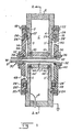
- a probe 8 introduces radio frequency energy into the cavity C.
- the disks 2 and 4 respectively have circular apertures 10 and 12 that are concentric therewith and which have a radius larger than the outer radius of a discharge tube D inserted therethrough.
- Circular metal or plastics discharge tube support members 14 and 16, herein shown as being of plastics material, are respectively attached to the exteriors of the disks 2 and 4 by screws 18, 20 and 22, 24.
- the support members 14 and 16 may have to be of metal, in accordance with the principle of having a sufficiently extensive grounding of the flow path.
- annular ribs 27 of the annular groove 26' space the central portion of the inner surface of the support member 14 from the exterior of the disk 2 to form a cylindrical space S therebetween; and corresponding ribs 29 of the annular groove 28' space the central portion of the inner surface of the support member 16 from the exterior of the disk 4 to form a cylindrical space S' therebetween.
- the circular discharge tube support members 14 and 16 are provided with circular central apertures 30 and 32 respectively that are coaxially aligned with the apertures 10 and 12 and that are just slightly larger than the discharge tube D that is coaxially mounted within all of the apertures 30,10,12 and 32.
- the discharge tube D is made of a refractory material of low microwave dissipation factor and high chemical inertness such as fused silica, boron nitride or crystalline alumina (sapphire) and is inserted through annular nuts 34 and 36 that are respectively screwed into threads formed on the inside surfaces of the apertures 30 and 32.
- a seal is provided between the exterior of the discharge tube D and an annular shoulder 37 in the aperture 30 by pressing a rubber 0-ring 38 between the shoulder 37 and the end of the annular nut 34.
- a seal is provided between the exterior of the discharge tube D and an annular shoulder 40 in the aperture 32 by pressing a rubber O-ring 42 between the shoulder 40 and the end of the annular nut 36.
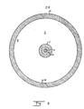
- An annular water jacket J that is made of quartz, polystyrene or any other low dielectric constant, low dissipation factor material is mounted concentrically with the discharge tube D and has an inner radius that is greater than the outer radius of the discharge tube D so as to form an annular passageway P therebetween.
- the radial dimension of the passageway P is preferably as small as possible but large enough to permit sufficient flow to prevent boiling of the coolant. If this dimension is too large, the microwave tuning of the cavity is shifted and may be dependent on the temperature of the cooling liquid. Also, microwave power is dissipated in the liquid, so it is advantageous to keep the volume of liquid contained within the cavity to a minimum.
- the passageway P is sealed from the inside of the cavity C by rubber O-rings 44 and 46 that are respectively embedded in annular grooves 44' and 46' that are concentric with the discharge tube D and of such radius that the O-rings 44 and 46 bear up against the opposite ends of the annular water jacket J.
- An aperture 48 through the support member 14 communicates with the outer part of the annular space S; and an aperture 50 through the support member 16 that is diametrically opposed to the aperture 48 communicates with the outer part of the annular space S'.
- the aperture 48, the cylindrical space S and the aperture 10 at the center of the disk 2 form a path via which coolant liquid may flow into one end of the passageway P;
- the cylindrical aperture 50, the annular space S' and the aperture 12 at the center of the disk 4 form a path via which coolant liquid may flow out of the passageway P.
- points along the paths referred to must be grounded so as to prevent the paths from acting as an antenna radiating microwave power outside the cavity C that is required for the formation of the gas discharge within the discharge tube D.
- the grounding is effected by the contact of the coolant liquid with the grounded cavity C at the inner surfaces of the apertures 54 and 56 respectively and with the outside portion of the walls 2 and 4 of the cavity C that form sides of the circular spaces S and S'. Good results have also been attained by grounding the paths at points farther away from the ends of the passageway P, but it is preferable to locate the ground points as near to the end of the passageway P as possible so as to reduce the length of the gas discharge in the discharge tube D and therefore reduce tailing.
- the paths through which the coolant liquid flows into and out of the annular passageway P are on opposite sides of the cavity C, but in embodiments not shown, good results can be obtained with a design in which both paths are on the same side of the cavity C.
- cavities having a different shape from the cylindrical one shown could be used, e.g., a cavity with a re-entrant section, and that the structure of the means for bringing the coolant into thermal communication with the discharge tube could be considerably different.
Landscapes
- Physics & Mathematics (AREA)
- Health & Medical Sciences (AREA)
- Life Sciences & Earth Sciences (AREA)
- Chemical & Material Sciences (AREA)
- Analytical Chemistry (AREA)
- Biochemistry (AREA)
- General Health & Medical Sciences (AREA)
- General Physics & Mathematics (AREA)
- Immunology (AREA)
- Pathology (AREA)
- Investigating, Analyzing Materials By Fluorescence Or Luminescence (AREA)
Applications Claiming Priority (2)
| Application Number | Priority Date | Filing Date | Title |
|---|---|---|---|
| US556527 | 1983-11-30 | ||
| US06/556,527 US4654504A (en) | 1983-11-30 | 1983-11-30 | Water-cooled gas discharge detector |
Publications (3)
| Publication Number | Publication Date |
|---|---|
| EP0145107A2 EP0145107A2 (en) | 1985-06-19 |
| EP0145107A3 EP0145107A3 (en) | 1987-08-19 |
| EP0145107B1 true EP0145107B1 (en) | 1990-10-31 |
Family
ID=24221722
Family Applications (1)
| Application Number | Title | Priority Date | Filing Date |
|---|---|---|---|
| EP84304114A Expired EP0145107B1 (en) | 1983-11-30 | 1984-06-19 | Gas discharge detectors |
Country Status (4)
| Country | Link |
|---|---|
| US (1) | US4654504A (enExample) |
| EP (1) | EP0145107B1 (enExample) |
| JP (1) | JPS60133357A (enExample) |
| DE (1) | DE3483516D1 (enExample) |
Families Citing this family (12)
| Publication number | Priority date | Publication date | Assignee | Title |
|---|---|---|---|---|
| US4965540A (en) * | 1987-12-23 | 1990-10-23 | Hewlett-Packard Company | Microwave resonant cavity |
| EP0321792A3 (en) * | 1987-12-23 | 1991-03-20 | Hewlett-Packard Company | Microwave resonant cavity |
| FR2637442B1 (fr) * | 1988-10-03 | 1990-11-02 | Aerospatiale | Dispositif pour la mise a poste et le retrait d'une torche a plasma sur un appareil fonctionnant sous pression et temperature interdisant une intervention directe |
| US5083004A (en) * | 1989-05-09 | 1992-01-21 | Varian Associates, Inc. | Spectroscopic plasma torch for microwave induced plasmas |
| US5022756A (en) * | 1989-11-03 | 1991-06-11 | Hewlett-Packard Company | Method and apparatus for spectrochemical analysis having maximum repeatability |
| EP0726593A1 (en) * | 1995-02-13 | 1996-08-14 | Applied Materials, Inc. | A high power, plasma-based, reactive species generator |
| US5895548A (en) * | 1996-03-29 | 1999-04-20 | Applied Komatsu Technology, Inc. | High power microwave plasma applicator |
| AT406527B (de) | 1997-03-04 | 2000-06-26 | Bernhard Dr Platzer | Vorrichtung zum analysieren gasförmiger proben |
| US6836060B2 (en) * | 2001-03-26 | 2004-12-28 | Agilent Technologies, Inc. | Air cooled gas discharge detector |
| US6774993B2 (en) | 2001-04-03 | 2004-08-10 | Agilent Technologies, Inc. | Method and apparatus for atomic emission spectroscopy |
| GB2435921A (en) * | 2005-12-23 | 2007-09-12 | Elan Vital | Portable fluid analyser system |
| CN118795304B (zh) * | 2024-07-25 | 2025-01-24 | 湖南信芯精密陶瓷有限公司 | 一种气体放电管生产用测试装置 |
Family Cites Families (7)
| Publication number | Priority date | Publication date | Assignee | Title |
|---|---|---|---|---|
| US3492074A (en) * | 1967-11-24 | 1970-01-27 | Hewlett Packard Co | Atomic absorption spectroscopy system having sample dissociation energy control |
| US3484650A (en) * | 1967-12-15 | 1969-12-16 | John F Rendina | Plasma atomic vapor generator |
| DE1910461B2 (de) * | 1969-03-01 | 1971-09-23 | Glimmentladungsroehre zur analyse von draehten und drahtfoer migen metallischen koerpern | |
| US3635561A (en) * | 1969-10-04 | 1972-01-18 | Cnen | Apparatus and method for determining the content of chemical elements in a solid sample |
| JPS5547690B2 (enExample) * | 1973-06-22 | 1980-12-02 | ||
| US4322165A (en) * | 1979-02-23 | 1982-03-30 | The Dow Chemical Company | VUV Plasma atomic emission spectroscopic instrument and method |
| US4394237A (en) * | 1981-07-17 | 1983-07-19 | Bell Telephone Laboratories, Incorporated | Spectroscopic monitoring of gas-solid processes |
-
1983
- 1983-11-30 US US06/556,527 patent/US4654504A/en not_active Expired - Lifetime
-
1984
- 1984-06-19 EP EP84304114A patent/EP0145107B1/en not_active Expired
- 1984-06-19 DE DE8484304114T patent/DE3483516D1/de not_active Expired - Lifetime
- 1984-11-27 JP JP59250357A patent/JPS60133357A/ja active Granted
Also Published As
| Publication number | Publication date |
|---|---|
| EP0145107A3 (en) | 1987-08-19 |
| EP0145107A2 (en) | 1985-06-19 |
| US4654504A (en) | 1987-03-31 |
| DE3483516D1 (de) | 1990-12-06 |
| JPH043819B2 (enExample) | 1992-01-24 |
| JPS60133357A (ja) | 1985-07-16 |
Similar Documents
| Publication | Publication Date | Title |
|---|---|---|
| EP0145107B1 (en) | Gas discharge detectors | |
| US4965540A (en) | Microwave resonant cavity | |
| US5063329A (en) | Microwave plasma source apparatus | |
| EP0874386B1 (en) | Apparatus and process for remote microwave plasma generation | |
| US7719195B2 (en) | Plasma lamp with field-concentrating antenna | |
| EP0397468B1 (en) | Spectroscopic plasma torch for microwave induced plasmas | |
| KR100329815B1 (ko) | 방위각및축상으로균등한전계를활용한플라즈마장치및활용방법 | |
| US4180763A (en) | High intensity discharge lamp geometries | |
| US20060208645A1 (en) | Plasma lamp with dielectric waveguide | |
| WO2008070002A1 (en) | Wide area radio frequency plasma apparatus for processing multiple substrates | |
| US4286240A (en) | Circular electric mode microwave window | |
| US5625259A (en) | Microwave plasma applicator with a helical fluid cooling channel surrounding a microwave transparent discharge tube | |
| US20020043342A1 (en) | Plasma generator | |
| US8981644B2 (en) | Lucent waveguide electromagnetic wave plasma light source | |
| US5568015A (en) | Fluid-cooled dielectric window for a plasma system | |
| JP2006164991A (ja) | マイクロ波プラズマ・システム用の液体冷却マイクロ波プラズマ・アプリケータおよび液体冷却誘電体窓 | |
| US6369493B1 (en) | Microwave plasma applicator having a thermal transfer medium between a plasma containing tube and a cooling jacket | |
| EP0321792A2 (en) | Microwave resonant cavity | |
| CN103891418B (zh) | 在多电极微波等离子体激发源中的电极冷却系统 | |
| JP2002541336A (ja) | 液体熱交換媒体供給ラインおよび排出ラインの無線周波数アイソレートを行うための方法および装置 | |
| US3434076A (en) | Waveguide window having circulating fluid of critical loss tangent for dampening unwanted mode | |
| EP2666179B1 (en) | Magnetron | |
| JP4004154B2 (ja) | プラズマ処理装置 | |
| KR100327537B1 (ko) | 마이크로웨이브조명기구 | |
| Schlie et al. | High UV (λ≥ 2200 Å), visible, and near infrared (λ≤ 0.8 μm) transmissive liquid coolant for high power microwave (2.45 GHz) plasma tubes |
Legal Events
| Date | Code | Title | Description |
|---|---|---|---|
| PUAI | Public reference made under article 153(3) epc to a published international application that has entered the european phase |
Free format text: ORIGINAL CODE: 0009012 |
|
| 17P | Request for examination filed |
Effective date: 19840622 |
|
| AK | Designated contracting states |
Designated state(s): DE FR GB |
|
| PUAL | Search report despatched |
Free format text: ORIGINAL CODE: 0009013 |
|
| AK | Designated contracting states |
Kind code of ref document: A3 Designated state(s): DE FR GB |
|
| 17Q | First examination report despatched |
Effective date: 19900201 |
|
| GRAA | (expected) grant |
Free format text: ORIGINAL CODE: 0009210 |
|
| AK | Designated contracting states |
Kind code of ref document: B1 Designated state(s): DE FR GB |
|
| REF | Corresponds to: |
Ref document number: 3483516 Country of ref document: DE Date of ref document: 19901206 |
|
| ET | Fr: translation filed | ||
| PLBE | No opposition filed within time limit |
Free format text: ORIGINAL CODE: 0009261 |
|
| STAA | Information on the status of an ep patent application or granted ep patent |
Free format text: STATUS: NO OPPOSITION FILED WITHIN TIME LIMIT |
|
| 26N | No opposition filed | ||
| PGFP | Annual fee paid to national office [announced via postgrant information from national office to epo] |
Ref country code: FR Payment date: 19960515 Year of fee payment: 13 |
|
| PG25 | Lapsed in a contracting state [announced via postgrant information from national office to epo] |
Ref country code: FR Free format text: LAPSE BECAUSE OF NON-PAYMENT OF DUE FEES Effective date: 19980227 |
|
| REG | Reference to a national code |
Ref country code: FR Ref legal event code: ST |
|
| REG | Reference to a national code |
Ref country code: FR Ref legal event code: ST |
|
| PGFP | Annual fee paid to national office [announced via postgrant information from national office to epo] |
Ref country code: DE Payment date: 19980527 Year of fee payment: 15 |
|
| PG25 | Lapsed in a contracting state [announced via postgrant information from national office to epo] |
Ref country code: DE Free format text: LAPSE BECAUSE OF NON-PAYMENT OF DUE FEES Effective date: 20000503 |
|
| REG | Reference to a national code |
Ref country code: GB Ref legal event code: IF02 |
|
| PGFP | Annual fee paid to national office [announced via postgrant information from national office to epo] |
Ref country code: GB Payment date: 20030611 Year of fee payment: 20 |
|
| PG25 | Lapsed in a contracting state [announced via postgrant information from national office to epo] |
Ref country code: GB Free format text: LAPSE BECAUSE OF EXPIRATION OF PROTECTION Effective date: 20040618 |
|
| REG | Reference to a national code |
Ref country code: GB Ref legal event code: PE20 |