EP0144609A2 - Diaphragm type pump device - Google Patents
Diaphragm type pump device Download PDFInfo
- Publication number
- EP0144609A2 EP0144609A2 EP84111969A EP84111969A EP0144609A2 EP 0144609 A2 EP0144609 A2 EP 0144609A2 EP 84111969 A EP84111969 A EP 84111969A EP 84111969 A EP84111969 A EP 84111969A EP 0144609 A2 EP0144609 A2 EP 0144609A2
- Authority
- EP
- European Patent Office
- Prior art keywords
- diaphragm
- cover
- operation chamber
- connecting rod
- frame
- Prior art date
- Legal status (The legal status is an assumption and is not a legal conclusion. Google has not performed a legal analysis and makes no representation as to the accuracy of the status listed.)
- Withdrawn
Links
Images
Classifications
-
- F—MECHANICAL ENGINEERING; LIGHTING; HEATING; WEAPONS; BLASTING
- F04—POSITIVE - DISPLACEMENT MACHINES FOR LIQUIDS; PUMPS FOR LIQUIDS OR ELASTIC FLUIDS
- F04B—POSITIVE-DISPLACEMENT MACHINES FOR LIQUIDS; PUMPS
- F04B43/00—Machines, pumps, or pumping installations having flexible working members
- F04B43/02—Machines, pumps, or pumping installations having flexible working members having plate-like flexible members, e.g. diaphragms
- F04B43/023—Machines, pumps, or pumping installations having flexible working members having plate-like flexible members, e.g. diaphragms double acting plate-like flexible member
Definitions
- the present invention relates to an improvement in a diaphragm type pump device.
- the diaphragm 2 is subjected to amplitude movement when the connecting rod 1 is reciprocatingly moved by a driving system (not shown).
- the volume of the operation chamber 6 increases as the connecting rod 1 is lowered in the direction of A and fluid is sucked from the intake port 7 through the check valve 9 in an opening state, while the check valve 10 is in a closing state.
- a diagram type pump device which comprises a connecting rod, a diaphragm connected to an end of the connecting rod, a cover which firmly secures the outer circumferential part of the diaphragm and constitutes a first operation chamber, a frame which opposes the cover to firmly secure the outer circumferential part of the diaphragm in association with the cover and constitutes a second operation chamber, and an intake port and a discharge port which are respectively communicated with the first operation chamber and the second operation chamber and provided with check valves each having different communicating direction, wherein the first and second operation chambers alternately perform pumping operation by the amplitude movement of the diaphragm due to a combination of the reciprocating movement of the connecting rod and the action of the check valves.
- a diaphragm type pump device of the present invention is generally constituted by a frame 19, a cover 13, a pair of end plates 25, 26, a diaphragm 2 fixed to the connecting rod 1 and check valves 17, 18, 23 and 24.
- the frame 19 has an insertion hole 19a through which the connecting rod extends upwardly so as to be movable by an external driving means.
- a sealing member 27 is provided at the insertion hole 19a to keep airtightness.
- the frame 19 also has an inner flange part 19b inwardly extends from the upper surface and two opposing openings 32, 33 are formed in the inner flange at positions near the upper surface of the frame 19.
- the cover 13 is placed opposing the frame 19 and has an inner flange 13a downwardly extending from the lower surface.
- Two opposing openings 30, 31 are formed in the inner flange 13a at positions near the lower surface of the cover 13.
- the outer circumferential part of the diaphragm 2, firmly secured at the top end of the connecting rod 1 by the nut 4, is clamped by opposing surfaces of the inner flanges of the cover 13 and the frame 19.
- a first operation chamber 14 is formed by the lower surface of the cover 13, the inner flange 13a and the diaphragm 2
- a second operation chamber 20 is formed by the upper surface of the frame 19, the inner flange 19b and the diaphragm 2.
- the end plates 25 and 26 are attached to openings formed at both sides of the cover 13 and the frame 19.
- the end plate 25 has an opening for intaking air and the end plate 26 has an opening for discharging air.
- the check valve 17 as a first check valve for intaking air is provided near the opening 30 to form a first intake port 15; the check valve 18 as a second check valve 18 is provided near the opening 31 to form a first discharge port 16; the check valve 23 as a third check valve is provided near the opening 32 to form a second intake port 21 and the check valve 24 as a fourth check valve is provided near the opening to form a second discharge port 22.
- the first and third check valves 17 and 23 act to only intake air and the second and fourth check valves 18 and 24 act to only discharge air.
- Reciprocating movement of the connecting rod 1 causes the amplitude movement of the diaphragm 2 as similar to the conventional device.
- the volume of the first operation chamber 14 increases as the connecting rod 1 is lowered in the direction of A, on account of which the first check valve 17 is opened and the second check valve is closed to thereby suck fluid through the first intake port 15.
- the volume of the second operation chamber 20 decreases whereby the fourth check valve 24 is opened and the third check valve 23 is closed with the consequence that the fluid in the second operation chamber 20 is discharged through the second discharge port 22.
- the first and second operation chambers 14, 20 alternately perform pumping operations by repeating the amplitude movement of the diaphragm.
- chambers formed at the upper and lower sides of a diaphragm is used as operation chambers for alternate pumping operations thereby obtaining a pump capacity of two times as much as the conventional device. It is, therefore, possible to miniaturize the shape of the pump while increasing its capacity in an economical manner. Further, pulsation of fluid can be remarkably reduced.
Abstract
Description
- The present invention relates to an improvement in a diaphragm type pump device.
- There has been proposed a device of this kind as shown in Figure 1.
- In the Figure, a reference numeral 1 designates a connecting rod; a
numeral 2 designates a diaphragm secured to an end of the connecting rod 1; anumeral 3 designates reinforcing plates for reinforcing the diaphragm; anumeral 4 designates a nut to fix thediaphragm 2 and thereinforcing plates 3 to the connecting rod 1; anumeral 5 designates a cover which secures the outer circumferential part of thediaphragm 2 in association with a frame 11 and constitutes anoperation chamber 6; anumeral 7 designates an intake port formed in thecover 5; anumeral 8 designates a discharge port formed in the cover; anumeral 9 designates a check valve provided in theintake port 7; anumeral 10 designates a check valve provided in thedischarge port 8; and anumeral 12 designates a fixing bolt. - The operation cf the conventional pump device snown in Figure 1 will be described.
- The
diaphragm 2 is subjected to amplitude movement when the connecting rod 1 is reciprocatingly moved by a driving system (not shown). - The volume of the
operation chamber 6 increases as the connecting rod 1 is lowered in the direction of A and fluid is sucked from theintake port 7 through thecheck valve 9 in an opening state, while thecheck valve 10 is in a closing state. - Conversely, the volume of the
operation chamber 6 decreases as the connecting rod is raised in the direction of B whereby thecheck valve 9 will be closed while thecheck valve 10 is opened and the fluid in theoperation chamber 6 is discharged through thedischarge port 8. Thus, pumping operation is effected by repeating the movement as mentioned above. - In the conventional diaphragm type pump device constructed as described above, since the pumping operation has been effected only at one side of the
operation chamber 6 constituted by thecover 5 and thediaphragm 2, the shape of the pump is disadvantageously large when a pump having a large capacity is required. - Further, when there is the problem of pulsation of fluid, it is necessary to increase the speed of the amplitude movement of the
diaphragm 2. The increased speed adversely affects the durability of thediaphragm 2. - It is an object of the present invention to eliminate the disadvantage of the conventional device and to aim at miniaturization of the shape of a pump device and reduction in pulsation of fluid.
- The foregoing and other objects of the present invention have been attained by providing a diagram type pump device which comprises a connecting rod, a diaphragm connected to an end of the connecting rod, a cover which firmly secures the outer circumferential part of the diaphragm and constitutes a first operation chamber, a frame which opposes the cover to firmly secure the outer circumferential part of the diaphragm in association with the cover and constitutes a second operation chamber, and an intake port and a discharge port which are respectively communicated with the first operation chamber and the second operation chamber and provided with check valves each having different communicating direction, wherein the first and second operation chambers alternately perform pumping operation by the amplitude movement of the diaphragm due to a combination of the reciprocating movement of the connecting rod and the action of the check valves.
- A more complete appreciation of the invention and many of the attendant advantages thereof will be readily obtained as the same becomes better understood by reference to the following detailed description when considered in connection with the accompanying drawing, wherein:
-
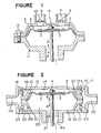
- Figure 1 is a cross sectional view of a conventional pump device; and
- Figure 2 is a cross-sectional view of the pump device of the present invention.
- An embodiment of the present invention will be described with reference to drawing. The same reference numerals designate the same parts and therefore, description of these parts is omitted.
- A diaphragm type pump device of the present invention is generally constituted by a
frame 19, acover 13, a pair ofend plates diaphragm 2 fixed to the connecting rod 1 andcheck valves - The
frame 19 has aninsertion hole 19a through which the connecting rod extends upwardly so as to be movable by an external driving means. A sealingmember 27 is provided at theinsertion hole 19a to keep airtightness. Theframe 19 also has aninner flange part 19b inwardly extends from the upper surface and twoopposing openings frame 19. - The
cover 13 is placed opposing theframe 19 and has an inner flange 13a downwardly extending from the lower surface. Twoopposing openings cover 13. The outer circumferential part of thediaphragm 2, firmly secured at the top end of the connecting rod 1 by thenut 4, is clamped by opposing surfaces of the inner flanges of thecover 13 and theframe 19. Thus, afirst operation chamber 14 is formed by the lower surface of thecover 13, the inner flange 13a and thediaphragm 2, while asecond operation chamber 20 is formed by the upper surface of theframe 19, theinner flange 19b and thediaphragm 2. - The
end plates cover 13 and theframe 19. Theend plate 25 has an opening for intaking air and theend plate 26 has an opening for discharging air. - The
check valve 17 as a first check valve for intaking air is provided near theopening 30 to form afirst intake port 15; thecheck valve 18 as asecond check valve 18 is provided near theopening 31 to form afirst discharge port 16; thecheck valve 23 as a third check valve is provided near theopening 32 to form asecond intake port 21 and thecheck valve 24 as a fourth check valve is provided near the opening to form asecond discharge port 22. The first andthird check valves fourth check valves - The operation of the embodiment of the present invention as shown in Figure 2 will be described.
- Reciprocating movement of the connecting rod 1 causes the amplitude movement of the
diaphragm 2 as similar to the conventional device. - The volume of the
first operation chamber 14 increases as the connecting rod 1 is lowered in the direction of A, on account of which thefirst check valve 17 is opened and the second check valve is closed to thereby suck fluid through thefirst intake port 15. - On the other hand, the volume of the
second operation chamber 20 decreases whereby thefourth check valve 24 is opened and thethird check valve 23 is closed with the consequence that the fluid in thesecond operation chamber 20 is discharged through thesecond discharge port 22. - When the connecting rod 1 is raised in the direction of B, the fluid sucked into the
first operation chamber 14 is discharged through thefirst discharge port 16 and a fresh fluid is sucked into thesecond operation chamber 20 from thesecond intake port 21. - The first and
second operation chambers - As described above, in accordance with the present invention, chambers formed at the upper and lower sides of a diaphragm is used as operation chambers for alternate pumping operations thereby obtaining a pump capacity of two times as much as the conventional device. It is, therefore, possible to miniaturize the shape of the pump while increasing its capacity in an economical manner. Further, pulsation of fluid can be remarkably reduced.
Claims (4)
Applications Claiming Priority (2)
| Application Number | Priority Date | Filing Date | Title |
|---|---|---|---|
| JP1983159818U JPS6066883U (en) | 1983-10-14 | 1983-10-14 | Diaphragm type pump device |
| JP159818/83U | 1983-10-14 |
Publications (2)
| Publication Number | Publication Date |
|---|---|
| EP0144609A2 true EP0144609A2 (en) | 1985-06-19 |
| EP0144609A3 EP0144609A3 (en) | 1986-12-03 |
Family
ID=15701915
Family Applications (1)
| Application Number | Title | Priority Date | Filing Date |
|---|---|---|---|
| EP84111969A Withdrawn EP0144609A3 (en) | 1983-10-14 | 1984-10-05 | Diaphragm type pump device |
Country Status (2)
| Country | Link |
|---|---|
| EP (1) | EP0144609A3 (en) |
| JP (1) | JPS6066883U (en) |
Cited By (2)
| Publication number | Priority date | Publication date | Assignee | Title |
|---|---|---|---|---|
| WO2013171453A1 (en) * | 2012-05-17 | 2013-11-21 | Selwood Group Limited | Diaphragm pump |
| US11002270B2 (en) * | 2016-04-18 | 2021-05-11 | Ingersoll-Rand Industrial U.S., Inc. | Cooling methods for electrically operated diaphragm pumps |
Families Citing this family (2)
| Publication number | Priority date | Publication date | Assignee | Title |
|---|---|---|---|---|
| KR101131922B1 (en) | 2010-03-09 | 2012-04-03 | 강소대 | Diaphragm with Upper and Lower Chamber |
| GB201322103D0 (en) | 2013-12-13 | 2014-01-29 | The Technology Partnership Plc | Fluid pump |
Citations (5)
| Publication number | Priority date | Publication date | Assignee | Title |
|---|---|---|---|---|
| US3461808A (en) * | 1967-07-03 | 1969-08-19 | Wood John Co | Diaphragm hand pumps |
| DE1907454B2 (en) * | 1968-02-22 | 1974-08-08 | Timothy James Francis Iver Buckinghamshire Roach (Grossbritannien) | Diaphragm pump |
| DE2511298A1 (en) * | 1974-03-15 | 1975-09-25 | Agrotechnika Np | GAS COMPRESSOR OR ENGINE |
| US4137020A (en) * | 1976-12-26 | 1979-01-30 | Nippondenso Co., Ltd. | Diaphragm type air pump |
| DE3140790A1 (en) * | 1981-10-14 | 1983-04-28 | Emil 4401 Laer Molzan | Kit for a diaphragm pump |
-
1983
- 1983-10-14 JP JP1983159818U patent/JPS6066883U/en active Pending
-
1984
- 1984-10-05 EP EP84111969A patent/EP0144609A3/en not_active Withdrawn
Patent Citations (5)
| Publication number | Priority date | Publication date | Assignee | Title |
|---|---|---|---|---|
| US3461808A (en) * | 1967-07-03 | 1969-08-19 | Wood John Co | Diaphragm hand pumps |
| DE1907454B2 (en) * | 1968-02-22 | 1974-08-08 | Timothy James Francis Iver Buckinghamshire Roach (Grossbritannien) | Diaphragm pump |
| DE2511298A1 (en) * | 1974-03-15 | 1975-09-25 | Agrotechnika Np | GAS COMPRESSOR OR ENGINE |
| US4137020A (en) * | 1976-12-26 | 1979-01-30 | Nippondenso Co., Ltd. | Diaphragm type air pump |
| DE3140790A1 (en) * | 1981-10-14 | 1983-04-28 | Emil 4401 Laer Molzan | Kit for a diaphragm pump |
Cited By (2)
| Publication number | Priority date | Publication date | Assignee | Title |
|---|---|---|---|---|
| WO2013171453A1 (en) * | 2012-05-17 | 2013-11-21 | Selwood Group Limited | Diaphragm pump |
| US11002270B2 (en) * | 2016-04-18 | 2021-05-11 | Ingersoll-Rand Industrial U.S., Inc. | Cooling methods for electrically operated diaphragm pumps |
Also Published As
| Publication number | Publication date |
|---|---|
| EP0144609A3 (en) | 1986-12-03 |
| JPS6066883U (en) | 1985-05-11 |
Similar Documents
| Publication | Publication Date | Title |
|---|---|---|
| EP0033096B1 (en) | Diaphragm pump | |
| KR101123933B1 (en) | Pump improvements | |
| US4749340A (en) | Piston type compressor with improved suction reed valve stopper | |
| WO1993018304A1 (en) | Hermetic compressor | |
| EP0431753A1 (en) | Reciprocating pump | |
| US4437490A (en) | Reed valve assembly | |
| US5577901A (en) | Compressor with valve unit for controlling suction and discharge of fluid | |
| US3645651A (en) | Pump | |
| EP0144609A2 (en) | Diaphragm type pump device | |
| US4560326A (en) | Diaphragm type pump device | |
| EP0824192A3 (en) | Fluid driven double diaphragm pump | |
| US3981631A (en) | Compressor head construction | |
| US3811803A (en) | Diaphragm pump | |
| US4610606A (en) | Gas refrigerant compressor including ported walls and a piston of unitary construction having a domed top | |
| CN211573746U (en) | Double-end air pump | |
| JP3962716B2 (en) | Fluid device having bellows and method for discharging residual air in fluid device | |
| KR100273421B1 (en) | Oil supplier of linear compressor | |
| CN210343659U (en) | Diaphragm pump | |
| EP0100301A1 (en) | Valve supporting plate for reciprocating engines and in particular for air compressors | |
| JP3755917B2 (en) | Compressor valve device | |
| EP3260748A1 (en) | Valve assembly | |
| CN219197592U (en) | Miniature vacuum air pump | |
| CN210531109U (en) | Water-gas mixing micropump and equipment thereof | |
| JPS5836867Y2 (en) | diaphragm pump | |
| CN217538965U (en) | Large-flow micro pump and pumping assembly thereof |
Legal Events
| Date | Code | Title | Description |
|---|---|---|---|
| PUAI | Public reference made under article 153(3) epc to a published international application that has entered the european phase |
Free format text: ORIGINAL CODE: 0009012 |
|
| AK | Designated contracting states |
Designated state(s): DE FR GB |
|
| PUAL | Search report despatched |
Free format text: ORIGINAL CODE: 0009013 |
|
| AK | Designated contracting states |
Kind code of ref document: A3 Designated state(s): DE FR GB |
|
| STAA | Information on the status of an ep patent application or granted ep patent |
Free format text: STATUS: THE APPLICATION IS DEEMED TO BE WITHDRAWN |
|
| 18D | Application deemed to be withdrawn |
Effective date: 19870604 |
|
| PGFP | Annual fee paid to national office [announced via postgrant information from national office to epo] |
Ref country code: LU Payment date: 19900913 Year of fee payment: 7 |
|
| RIN1 | Information on inventor provided before grant (corrected) |
Inventor name: OGAWA, HITOSHI |