EP0144567A2 - Process for the electrolysis of an aqueous alkali metal halide solution - Google Patents
Process for the electrolysis of an aqueous alkali metal halide solution Download PDFInfo
- Publication number
- EP0144567A2 EP0144567A2 EP84110805A EP84110805A EP0144567A2 EP 0144567 A2 EP0144567 A2 EP 0144567A2 EP 84110805 A EP84110805 A EP 84110805A EP 84110805 A EP84110805 A EP 84110805A EP 0144567 A2 EP0144567 A2 EP 0144567A2
- Authority
- EP
- European Patent Office
- Prior art keywords
- cathode
- compartment
- catholyte liquor
- gas
- cation exchange
- Prior art date
- Legal status (The legal status is an assumption and is not a legal conclusion. Google has not performed a legal analysis and makes no representation as to the accuracy of the status listed.)
- Withdrawn
Links
Images


Classifications
-
- C—CHEMISTRY; METALLURGY
- C25—ELECTROLYTIC OR ELECTROPHORETIC PROCESSES; APPARATUS THEREFOR
- C25B—ELECTROLYTIC OR ELECTROPHORETIC PROCESSES FOR THE PRODUCTION OF COMPOUNDS OR NON-METALS; APPARATUS THEREFOR
- C25B15/00—Operating or servicing cells
- C25B15/08—Supplying or removing reactants or electrolytes; Regeneration of electrolytes
-
- C—CHEMISTRY; METALLURGY
- C25—ELECTROLYTIC OR ELECTROPHORETIC PROCESSES; APPARATUS THEREFOR
- C25B—ELECTROLYTIC OR ELECTROPHORETIC PROCESSES FOR THE PRODUCTION OF COMPOUNDS OR NON-METALS; APPARATUS THEREFOR
- C25B1/00—Electrolytic production of inorganic compounds or non-metals
- C25B1/01—Products
- C25B1/34—Simultaneous production of alkali metal hydroxides and chlorine, oxyacids or salts of chlorine, e.g. by chlor-alkali electrolysis
- C25B1/46—Simultaneous production of alkali metal hydroxides and chlorine, oxyacids or salts of chlorine, e.g. by chlor-alkali electrolysis in diaphragm cells
Definitions
- the present invention generally relates to an electrolytic process for electrolysis of an aqueous alkali metal halide solution, especially an aqueous alkali metal chloride solution. More particularly it relates to a process for mainly obtaining a high quality caustic alkali more effectively with low cell voltage using a horizontal type electrolytic cell providing a cation exchange membrane as an electrolytic separator.
- the most typical horizontal electrolytic cell is a mercury electrolytic cell but destined to be shut down in the near future in Japan since mercury served as a cathode contaminates environment.
- the separator electrolytic cell should be of a horizontal type.
- a process for retrofitting a mercury cell to a horizontal type separator cell is revealed in the United States Patent No. 3,923,614.
- a porous membrane diaphragm
- anolyte solution passes through the separator hydraulically to thus mingle in, for example, caustic alkali produced in the cathode compartment, thereby resulting in decreased quality.
- a cation exchange membrane called a nonporous membrane permits no passage of anolyte solution or catholyte liquor hydraulically, allowing only water molecules coordination-bonded to alkali metal ions transported electrically to pass, hence a high quality caustic alkali being obtained.
- a small quantity of water transported evaporates to cause electric conduction failure between a membrane and a cathode, in the long run to terminate electrolytic reaction.
- the United States Patent No. 3,901,774 proposes processes to solve these problems ; one is a process for placing a liquid maintaining material between a cation exchange membrane and a cathode and another is a process for carrying out the electrolysis while supplying to a cathode an aqueous caustic alkali liquor in mist or spray.
- the former process not only involves the problems including troubles for interposing the liquid maintaining material and the durability thereof, but increases cell voltage because the distance between electrodes is expanded by the liquid maintaining material located between the cation exchange membrane and the cathode, besides an increase in electric resistance of the liquid maintaining material per se. Hence it can not be an advantageous process. Moreover the latter process has some difficulties in practice on an industrial scale since the uniform supply of liquid is difficult when applied to a large-scale electrolytic cell such as employed commercially.
- a perforated cathode having an aperture of from 90 to 10% such as expanded metal sheets, punched metal sheets, nets, louver-like cathodes is used and evolved gas is removed behind the cathode.
- An object of the present invention is to obtain a high quality caustic alkali with high efficiency using a horizontal type separator electrolytic cell.
- Another object of the present invention is to provide an improved electrolytic process permitting no residence of cathode gas in a space formed between a cation exchange membrane and a cathode.
- a further object of the present invention is to provide an electrolytic process which enables retrofit of a mercury electrolytic cell to a horizontal type cation exchange membrane electrolytic cell.
- the present invention is concerned with an electrolytic process by the use of a horizontal electrolytic cell partitioned by a cation exchange membrane positioned substantially horizontal into an upper anode compartment and a lower cathode compartment, said cathode compart- . ment having therein a gas-liquid impermeable cathode plate, wherein electrolysis is effected while supplying into the cathode compartment catholyte liquor for enfolding cathode gas generated in a space formed between the cation exchange membrane and the cathode plate to form a mixed stream of the cathode gas and the catholyte liquor, and discharging the mixed stream from the cathode compartment, said catholyte liquor having the flow rate satisfying the following equation ; wherein Y is linear velocity (cm/sec ) of the catholyte liquor containing no cathode gas or containg cathode gas in an extremely small amount, and X is length (m ) of a passageway of the catholyt
- the anode compartment or the cathode compartment may be provided but less-corrosive electrolyte is preferred because a great amount of electrolyte has to be supplied and circulated. That is, the cathode compartment had better be provided under the membrane.
- the present invention has been completed on the discovery through an extensive series of studies by the present inventors using a horizontal cation exchange membrane electrolytic cell providing the cathode compartment under the membrane that the residence of cathode gas in a space between the cathode and the membrane can be prevented by serving a gas-liquid impermeable cathode plate and, in consequence, a high quality caustic soda can be obtained with low cell voltage with high efficiency, and further that problems attendant on the conventional arts can be solved by controlling to the specific value or more initial linear velocity of catholyte liquor supplied to the cathode compartment which has a close relation with the residence of gas and cell voltage.
- FIG. 1 is a graph showing the relative relationship between the initial linear velocity of the catholyte liquor and cell voltage.
- the initial linear velocity hereby means the following. That is, the catholyte liquor supplied into the cathode compartment entrains gas-evolved by the electrolysis while flowing in the cathode compartment so that the velocity of the catholyte liquor flow generally increases as approaching to the outlet.
- the linear velocity of the catholyte liquor containing no gas in the neighborhood of the catholyte liquor inlet or containing a small amount of gas, if any is called the initial linear velocity.
- the abrupt decrease of cell voltage up to the first turning point is supposed to take place because of a rapid reduction in the residence of gas on the underside of the cation exchange membrane with an increase in the velocity.
- the slow decrease of cell voltage from the first turning point to the second turning point is probably caused by a decreased deposition of gas onto the surfaces of the cathode and the cation exchange membrane with an increase in the velocity.
- FIG. 2 there are given the results obtained by measuring cell voltage at the initial linear velocity varied in current density between 5 A /d nf and 80 A /d nf using an electrolytic cell having the catholyte liquor passageway of 70 cm. It has been found out by the present inventors that although the turning points as seen in FIG. 2 appear at approximately the same initial linear velocity in the range of from about 5 to about 80 A /d m, having almost no connection with current density, those shift to the side of higher initial linear velocity as the distance from a catholyte liquor inlet to an outlet (i. e., passageway of the catholyte liquor) becomes long.
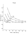
- FIG. 3 shows the results obtained by measuring cell voltage at various initial linear velocity of the catholyte liquor maintaining current density constant at 40 A /d m, by the use of various electrolytic cells having the catholyte liquor passageway ranging from 20 cm to 15 m.
- the cation exchange membrane used suitably in the present invention includes, for example, membranes made of perfluorocarbon polymers having cation exchange groups.
- the membrane made of a perfluorocarbon polymer containing sulfonic acid groups as a cation exchange group is sold by E. I. Du Pont de Nemours & Company under the trade mark "NAFiON" having the following chemical structure;
- the equivalent weight of such cation exchange membranes is preferred in a range between 1,000 and 2,000, more preferably in a range between 1,100 and 1,500.
- the equivalent weight herein means weight (g ) of a dry membrane per equivalent of an exchange group.
- membranes whose sulfonic acid groups are substituted, partly or wholly, by carboxylic acid groups and other membranes widely used can also be applied to the present invention.
- These cation exchange membranes exhibit very small water permeability so that they permit the passage of only sodium ion with three to four molecules of water, while hindering the passage of hydraulic flow.
- FIG. 5 is a partial cutaway front view showing a horizontal electrolytic cell of the present invention.
- an electrolytic cell of the present invention is comprised of an anode compartment (1 ) and a cathode compartment (2 ) located thereunder, both compartments being of a rectangular shape having the greater length than the width, preferably several times the length.
- the anode compartment (1 ) and the cathode compartment (2 ) are separated from each other by a cation exchange membrane (3 ) positioned substantially horizontal between side walls of the compartments.
- the word "substantially horizontal also includes the cases where the membrane is positioned slightly slant (up to a slope of about 2/10) .
- the anode compartment (I ) is formed by being surrounded by a top cover (4 ) , side walls (5 ) of the anode compartment located so as to enclose anode plates (12) and the upper side of a cation exchange membrane (3 ) .
- the anodes plates (12) are suspended by anode-suspending devices (7 ) located on the top cover (4 ) via anode-conducting rods (6 ) and are connected to one another by an anode busbar (8 ) .
- the top cover (4 ) possesses holes (10) through which anode conducting rod covers (9 ) are inserted and the holes (10) are sealed airtight by sheets (11) . To the lower ends of the rod covers (9 ) , are the anode plates (12) secured.
- the anode plates (12) are connected to the anode-suspending devices (7 ) , so that those can be ascended and descended by the adjustment of the anode-suspending devices (7 ) , thereby being positioned so as to come into contact with the cation exchange membrane (3).
- the anodes may also be suspended by other means, not being limited to the cases where those are suspended from the anode-suspending devices positioned to the top cover.
- the anodes may be suspended by being secured to an anode compartment frame which is fabricated of the top cover and the side walls, united in one body.
- the anode compartment is provided with at least one anolyte solution inlet (13) , which may be positioned to the top cover (4 ) or side walls (5 ) of the anode compartment.
- uniformity of anolyte solution in the anode compartment may also be attained by providing an anolyte solution supplying pipe with perforations, extending over the full length of the anode compartment, and supplying it through the perforations.
- the depleted brine if necessary, may be partly recirculated to make concentration and pH of anolyte solution uniform in the anode compartment.
- at least one anolyte solution outlet (14) is provided and may be positioned to the side walls (5 ) .
- anode gas (chlorine gas) outlet is provided.
- the anolyte solution outlet (14) and the anode gas outlet (15) need not necessarily be provided separately, and in some cases, the anolyte solution and the anode gas may be discharged through the common outlet, then subjected to gas-liquid separation outside the cell.
- a top cover and side walls of an anode compartment of a mercury electrolytic cell may also be converted - and any chlorine-resistant material may be effectively used.
- any chlorine-resistant material are chlorine-resistant metals such as titanium and an alloy thereof, fluorocarbon polymers, hard rubbers and the like.
- iron lined with the foregoing metals, fluorocarbon polymers, hard rubbers and the like may also be employed.
- perforated electrodes such as expanded matal sheets, net-like or louver-like electrodes, spaghetti-like electrodes and the like may be employed in order to rapidly discharge gas upwardly or non- perforated electrades may also be employed to thereby circulate anolyte solution between the electrode and the membrane.
- the foregoing anodes may be fabricated from titanium, niobium, tantalum, an alloy thereof, on the surface of which is coated with platinum group metals, electroconductive oxides thereof and the like.
- anode plates used in a mercury electrolytic cell may be directly converted without altering dimensions and shapes.
- the cathode compartment (2 ) is formed by being surrounded by. the underside of the cation exchange membrane (3 ) , a cathode plate (16) and side walls (17) of the cathode compartment positioned so as to enclose the cathode plate along the periphery of the cathode.plate.
- the side walls (17) of the cathode compartment may be made of those such as frames having some rigidity or may also be made of those such as packings of rubbers, plastics and the like.
- the portion of the bottom plate opposing the anodes through the cation exchange membrane is shaved off except the periphery and the remaining.
- the cathode compartment may be formed as below; That is, a thin layer packing is placed on the periphery of the cathode plate, the anode plates are located upper than the lower flange level of side walls forming the anode compartment and the cation exchange membrane is located along the inside surfaces of the side walls of the anode compartment utilizing the flexibility of the membrane to thus form the cathode compartment.
- any material resistant to caustic alkali such as sodium hydroxide may be used including, for example, iron, stainless steel, nickel and an alloy thereof. Iron base material lined with alkali- resistant materials may also be suitably used. Materials such as rubbers and plastics may also be used. As those materials, there are exemplified rubbers such as natural rubber, butyl rubber and ethylene-propylene rubber (EPR ) , fluorocarbon polymers such as polytetrafluoroethylene, copolymers of tetrafluoroethylene-hexafluoropropylene and copolymers of etylene-tetrafluoroethylene, polyvinyl chloride and reinforced plastics.
- EPR ethylene-propylene rubber
- a bottom plate used in a mercury electrolytic cell may be economically served.
- the surface of the bottom plate becomes coarse owing to corrosion, errosion caused by mercury, electrical short-circuit and the like, and therefore when the bottom plate is directly served, the cation exchange membrane occasionally rubs against the coarse surface to thereby be damaged.
- the smoothing may be attained by plating with nickel, cobalt, chrome, molybdenum, tungsten, platinum group metals, silver and the like, bonding of a thin metal plate made of nickel, austenitic stainless steel and the like, mechanical polishing or other suitable manners.
- the gas-liquid impermeable cathode plate may be in any form that does not prevent the catholyte liquor from flowing.
- the cathode plate may have substantially flat surface or may have such a protuberant structure surface as provided parallel in the flowing direction of the catholyte liquor.
- the cathode plate may also have small protrusions on its surface at a suitable interval.
- the protuberant structure may be given by shaving off a flat plate to thus form ditches in parallel to one another, welding a plurality of thin rods such as round rods and square rods to flat plate or by uniting protuberances and a flat plate.
- the cathode plate may be made of a corrugated plate.
- the corrugation may be in any form such as rectangular, trapezoidal, sinusoidal or cycloidal shape.
- the protuberant structure need not necessarily be continuous to a longitudinal way and may be intermittent for the purpose.
- the concave ditches or convex protuberances may not be limited to be provided along the flowing direction of the catholyte liquor, but may be provided in the direction traverse to the flowing direction of the catholyte liquor.
- the gas-liquid impermeable cathode plate providing ditches or protuberances extending along the flowing direction of the catholyte liquor it is a preferred embodiment to position the cation exchange membran to be in contact with or in close proximity to the convexities such as protuberances or protrusions.
- the cathode plate providing ditches or protuberances in the direction traverse to the flowing direction of the catholyte liquor it is preferred to keep the membrane about 1 to 5 mm apart from the convexities.
- dispersion in the flow rate of the catholyte liquor is uniformed by ditches or protuberances to thus minimize dispersion in the direction traverse to the flowing direction of the catholyte liquor, so that operation is effected under good conditions.
- the gas-liquid impermeable cathode plate may be fabricated from iron, stainless steel, nickel, nickel alloys and the like.
- One of preferred embodiment is to employ the cathode plate whose surface was subjected to plasma or flame spray with nickel, cobalt, chrome, molybdenum, tungsten, platinum group metals, silver, alloys of foregoings or mixtures of foregoings or plating or codeposit plating with foregoings with a view to reducing hydrogen overvoltage.
- a catholyte liquor inlet (19) and a mixed stream outlet (20) are not specifically limited but sufficient provided that those allow a flow of the catholyte liquor to occur in the cathode compartment (2 ) . Accordingly the flow of the catholyte liquor may be formed either to a longitudinal direction or to a traverse direction of the cell, but the latter is preferred since pressure difference between the inlet and the outlet and the value of G / (G +L ) (gas content contained in unit volume of the catholyte liquor) are reduced. For this purpose, the employment of a slit-like inlet is preferred. When a bottom plate of a mercury electrolytic cell is converted as cathode plate, existing bolt holes made thereon for assembly of the cell may be serviceable, directly or with necessary processing, as inlet or outlet.
- the catholyte liquor may be supplied or discharged through a flange of a side wall of the anode compartment or a periphery of the cathode plate opposite the flange in the direction substantially vertical to the direction of the horizontal surface of the cathode plate, whereby an anode-cathode distance can be minimized.
- FIG. 6 there is given a schematic illustration of a catholyte liquor-circulating system using the horizontal electrolytic cell shown by FIG. 5.
- an approaximately saturated brine is supplied through the anolyte solution inlet (13) into the anode compartment (1 ) and then electrolysed therein. Chlorine gas generated is removed through the anode gas outlet and depleted brine is discharged through the anolyte solution outlet.
- the catholyte liquor is supplied through the catholyte liquor inlet (19) into the cathode compartment (2 ) and mixed with hydrogen gas evolved in the cathode compartment to provide a mixed stream, discharged through the outlet (20) of the mixed stream, then the mixed stream being transported to a gas-liquid separating device (21) in which hydrogen gas is separated from caustic liquor.
- the catholyte liquor containing substantially no hydrogen gas is recirculated by use of a pump (22) through the catholyte liqour inlet (19) to the cathode compartment.
- the gas-liquid separating device (21) and the pump (22) may be one, respectively, for a plurality of cells, otherwise, for each cell.
- the electric current is supplied to an anode busbar (8 ) , passes through the cathode plate (16) of the cathode compartment (2 ) and then is taken out from a cathode busbar (18) .
- the present invention is very effective for preventing vibration of the membrane and consequently extending the lifetime to effect the electrolysis while pressing a portion of the membrane substantially taking part in the electrolysis against anodes.
- the pressing of the membrane against the anodes may be attained by known processes. For example, by choking a valve provided to the catholyte liquor outlet,pressure can be imposed on the whole cathode side of the membrane. It may also be achieved by the pressure of hydrogen gas generated on the cathode. It may further be attained by attracting the membrane to the anode side with increased sucking force of anode gas.
- the positive pressure imposed on the cathode side of the cation exchange membrane in the vicinity of the catholyte liquor outlet i. e., difference in pressure on the membrane between the anode side and the cathode side should be greater than a change in pressure imposed on the membrane.
- a change in pressure is between about 100 mm H 2 O and about 1,000mm H 2 O.
- the difference in pressure required to be imposed on the membrane is at least about 100 mm H 2 O and not exceeding about 10 m H 2 O.
- the difference in pressure exceeding about 10 m H 2 O is to press the membrane against the anodes with force stronger than required and hence leads to damage of the membrane.
- NAFION 901 (sold by E.I.Du Pont de Nemours & Co.) served as a cation exchange membrane, was positioned substantially horizontal over a substantially flat cathode plate comprising a bottom plate of a mercury electrolytic cell whose surface was subjected to plasma flame spray with nickel, having the length of 11 m and the width 1.8 m.
- Said cathode plate was provided with partitions of a soft rubber, 2.5 mm high and 7 mm wide, arranged at an interval of 35 cm in the traverse direction to the longitudinal way of the cathode plate and the top of the partitions was brought into contact with the membrane.
- Supply or removal of the catholyte liquor was made through a branch pipe for each partition so that the length of passageway of the chatholyte liquor was substantially 1.8 m.
- a DSE for use in a mercury electrolytic cell i. e. a titanium expanded metal sheet whose surface was coated with Ru0 2 and TiO 2 was used and situated so as to bring a working surface of the anode into contact with the membrane.
- Electrolytic cell so constructed and an operation system were such as shown by FIG. 5 and FIG. 6, though partitions were further provided on the cathode plate shown by FIG.5.
- a part of depleted brine was recirculated to control concentration of the depleted brine to 3.5 N, while in a cathode compartment a part of catholyte liquor was recirculated to control concentration of caustic soda to 32 %.
- the temperature was maintained at 85 ⁇ 1°C at current density of 30 A /d m 2 .
- Cell voltage was measured while supplying the catholyte liquor for the initial linear velocity within the cathode compartment to be 5 cm/sec, 15 cm/sec, 30 cm/sec and 50 cm /sec, respectively.
- NAFION 901 As a cation exchange membrane, "NAFION 901" was used and positioned substantially horizontal to a horizontal electrolytic cell provided with a cathode plate having a working surface, 11 m long and 1.8 m wide.
- the cathode plate possessed ditches, 6 mm deep and 8 mm wide at an interval of 16 mm, running parallel to the longitudinal direction and situated so as to bring the convexities formed between adjacent ditches into contact with the membrane.
- a titanium expanded metal sheet whose surface was coated with a solid solution of Ru0 2 and Ti02was used and situated to come in contact with the upper surface of the membrane.
Abstract
Description
- The present invention generally relates to an electrolytic process for electrolysis of an aqueous alkali metal halide solution, especially an aqueous alkali metal chloride solution. More particularly it relates to a process for mainly obtaining a high quality caustic alkali more effectively with low cell voltage using a horizontal type electrolytic cell providing a cation exchange membrane as an electrolytic separator.
- The most typical horizontal electrolytic cell is a mercury electrolytic cell but destined to be shut down in the near future in Japan since mercury served as a cathode contaminates environment. When such a mercury cathode electrolytic cell is desired to be converted into a separator electrolytic cell employing no mercury with a reduced cost, the separator electrolytic cell should be of a horizontal type. In view of the situation, it is a significant matter the industry is now encountering to develop a process for producing a high quality product, not inferior to a product by the mercury process, with a high current efficiency using such horizontal type separator electrolytic cells.
- A process for retrofitting a mercury cell to a horizontal type separator cell is revealed in the United States Patent No. 3,923,614. In the process, however, a porous membrane (diaphragm ) is used to serve as a separator, having great water permeability and accordingly anolyte solution passes through the separator hydraulically to thus mingle in, for example, caustic alkali produced in the cathode compartment, thereby resulting in decreased quality.
- On the other hand, a cation exchange membrane called a nonporous membrane permits no passage of anolyte solution or catholyte liquor hydraulically, allowing only water molecules coordination-bonded to alkali metal ions transported electrically to pass, hence a high quality caustic alkali being obtained. To the contrary, a small quantity of water transported evaporates to cause electric conduction failure between a membrane and a cathode, in the long run to terminate electrolytic reaction.
- The United States Patent No. 3,901,774 proposes processes to solve these problems ; one is a process for placing a liquid maintaining material between a cation exchange membrane and a cathode and another is a process for carrying out the electrolysis while supplying to a cathode an aqueous caustic alkali liquor in mist or spray.
- Notwithstanding, the former process not only involves the problems including troubles for interposing the liquid maintaining material and the durability thereof, but increases cell voltage because the distance between electrodes is expanded by the liquid maintaining material located between the cation exchange membrane and the cathode, besides an increase in electric resistance of the liquid maintaining material per se. Hence it can not be an advantageous process. Moreover the latter process has some difficulties in practice on an industrial scale since the uniform supply of liquid is difficult when applied to a large-scale electrolytic cell such as employed commercially.
- On the other hand, in effecting electrolysis using a horizontal electrolytic cell providing a cation exchange membrane positioned substantially horizontal, it is important to prevent cathode gas generated on a cathode from residing on the underside of the membrane, i. e., to keep the underside of the membrane in contact with catholyte liquor. Convensionally, the cation exchange membrane has been used in a vertical type electrolytic cell. In this case, for the purpose of rapidly removing cathode gas evolved on the cathode from a space between the cathode and the cation exchange membrane, a perforated cathode having an aperture of from 90 to 10% such as expanded metal sheets, punched metal sheets, nets, louver-like cathodes is used and evolved gas is removed behind the cathode. Nontheless, in the case of the horizontal type electrolytic cell, it is impossible to cause gas evolved on the cathode below the cation exchange membrane to discharge behind the cathode, i. e., underneath the cathode against the buoyancy. For the reasons, the space between the cathode and the membrane is filled with cathode gas which impedes electric conduction.
- In order to eliminate the foregoing defects, a process is considered in which catholyte liquor is circulated in the space between the cathode and the membrane to remove evolved gas together with the circulated catholyte liquor from the cathode compartment. With the conventional perforated cathodes, however, the circulated catholyte liquor is dispersed underneath the perforated cathode so that residence of gas in the space between the cathode and the membrane can not be prevented perfectly. As a result, part of gas resides to thus result in an increase in cell voltage.
- An object of the present invention is to obtain a high quality caustic alkali with high efficiency using a horizontal type separator electrolytic cell.
- Another object of the present invention is to provide an improved electrolytic process permitting no residence of cathode gas in a space formed between a cation exchange membrane and a cathode.
- A further object of the present invention is to provide an electrolytic process which enables retrofit of a mercury electrolytic cell to a horizontal type cation exchange membrane electrolytic cell.
- Other objects of the present invention will be made apparent from the following description.
-
- FIG. 1 is a graph showing the relative relationship between initial linear velocity of catholyte liquor in a cathode compartment and cell voltage.
- FIG. 2 is a graph showing the relationship among current density, initial linear velocity and cell voltage.
- FIG. 3 is a graph showing the relationship among the length of cell, initial linear velocity and cell voltage.
- FIG. 4 is a graph showing the relationship between the length of catholyte liquor passageway and initial linear velocity at the first turning point shown by FIG. 2 and FIG. 3._
- FIG. 5 is a partial cutaway front view illustrating an embodiment of a horizontal type electrolytic cell used in the present invention.
- FIG. 6 is a schematic illustration showing a catholyte liquor-circulating system.
- The present invention is concerned with an electrolytic process by the use of a horizontal electrolytic cell partitioned by a cation exchange membrane positioned substantially horizontal into an upper anode compartment and a lower cathode compartment, said cathode compart- . ment having therein a gas-liquid impermeable cathode plate, wherein electrolysis is effected while supplying into the cathode compartment catholyte liquor for enfolding cathode gas generated in a space formed between the cation exchange membrane and the cathode plate to form a mixed stream of the cathode gas and the catholyte liquor, and discharging the mixed stream from the cathode compartment, said catholyte liquor having the flow rate satisfying the following equation ;

- In the present invention, under the cation exchange membrane the anode compartment or the cathode compartment may be provided but less-corrosive electrolyte is preferred because a great amount of electrolyte has to be supplied and circulated. That is, the cathode compartment had better be provided under the membrane.
- The present invention has been completed on the discovery through an extensive series of studies by the present inventors using a horizontal cation exchange membrane electrolytic cell providing the cathode compartment under the membrane that the residence of cathode gas in a space between the cathode and the membrane can be prevented by serving a gas-liquid impermeable cathode plate and, in consequence, a high quality caustic soda can be obtained with low cell voltage with high efficiency, and further that problems attendant on the conventional arts can be solved by controlling to the specific value or more initial linear velocity of catholyte liquor supplied to the cathode compartment which has a close relation with the residence of gas and cell voltage.
- Investigation was made as to the relationship between the initial linear velocity within the cathode compartment of the catholyte liquor supplied to the cathode compartment and cell voltage. FIG. 1 is a graph showing the relative relationship between the initial linear velocity of the catholyte liquor and cell voltage.
- In the present invention, the initial linear velocity hereby means the following. That is, the catholyte liquor supplied into the cathode compartment entrains gas-evolved by the electrolysis while flowing in the cathode compartment so that the velocity of the catholyte liquor flow generally increases as approaching to the outlet. Hence, the linear velocity of the catholyte liquor containing no gas in the neighborhood of the catholyte liquor inlet or containing a small amount of gas, if any, is called the initial linear velocity.
- As is apparent from FIG. 1, the cell voltage-decreases abruptly with an increase in velocity of the catholyte liquor supplied, then decreases gradually, thereafter arrives at the steady state approximately. The abrupt decrease of cell voltage up to the first turning point is supposed to take place because of a rapid reduction in the residence of gas on the underside of the cation exchange membrane with an increase in the velocity. The slow decrease of cell voltage from the first turning point to the second turning point is probably caused by a decreased deposition of gas onto the surfaces of the cathode and the cation exchange membrane with an increase in the velocity.
- In FIG. 2, there are given the results obtained by measuring cell voltage at the initial linear velocity varied in current density between 5 A /d nf and 80 A /d nf using an electrolytic cell having the catholyte liquor passageway of 70 cm. It has been found out by the present inventors that although the turning points as seen in FIG. 2 appear at approximately the same initial linear velocity in the range of from about 5 to about 80 A /d m, having almost no connection with current density, those shift to the side of higher initial linear velocity as the distance from a catholyte liquor inlet to an outlet (i. e., passageway of the catholyte liquor) becomes long.
- FIG. 3 shows the results obtained by measuring cell voltage at various initial linear velocity of the catholyte liquor maintaining current density constant at 40 A /d m, by the use of various electrolytic cells having the catholyte liquor passageway ranging from 20 cm to 15 m.
- In FIG. 4, corresponding points between the initial linear velocity and the catholyte liquor at the first turning point in FIG. 2 and FIG. 3 were obtained and plotted, with the length of catholyte liquor passageway as.abscissa and the initial linear velocity as ordinate. As obvious from FIG. 4, the initial linear velocity for obtaining cell voltage lower than the first turning point should be within a range satisfying the following equation ;

- Y : initial linear velocity (cm/sec )
- X : catholyte liquor passageway length (m ) Therefore, in obtaining a high quality caustic soda with high efficiency at low cell voltage according to the electrolytic process of the present invention, it is necessary to operate while maintaining the initial linear velocity, at which the catholyte liquor is supplied to the cathode compartment, satisfying the equation (I) .
- The cation exchange membrane used suitably in the present invention includes, for example, membranes made of perfluorocarbon polymers having cation exchange groups. The membrane made of a perfluorocarbon polymer containing sulfonic acid groups as a cation exchange group is sold by E. I. Du Pont de Nemours & Company under the trade mark "NAFiON" having the following chemical structure;

- The equivalent weight of such cation exchange membranes is preferred in a range between 1,000 and 2,000, more preferably in a range between 1,100 and 1,500. The equivalent weight herein means weight (g ) of a dry membrane per equivalent of an exchange group. Moreover membranes whose sulfonic acid groups are substituted, partly or wholly, by carboxylic acid groups and other membranes widely used can also be applied to the present invention. These cation exchange membranes exhibit very small water permeability so that they permit the passage of only sodium ion with three to four molecules of water, while hindering the passage of hydraulic flow.
- Hereinafter, embodiments of the present invention will be explained in detail by referring to the drawings attached. The following explanation is referred, as a matter of convenience, to sodium chloride which is most popular in the industry and typical of alkali metal halides, and to caustic soda as an electrolytic product, but to which the present invention is not limited, the present invention being, needlessly, applied to the electrolysis of an aqueous solution of other inorganic salts such as potassium chloride, water and the like.
- FIG. 5 is a partial cutaway front view showing a horizontal electrolytic cell of the present invention.
- In FIG. 5, an electrolytic cell of the present invention is comprised of an anode compartment (1 ) and a cathode compartment (2 ) located thereunder, both compartments being of a rectangular shape having the greater length than the width, preferably several times the length. The anode compartment (1 ) and the cathode compartment (2 ) are separated from each other by a cation exchange membrane (3 ) positioned substantially horizontal between side walls of the compartments. The word "substantially horizontal also includes the cases where the membrane is positioned slightly slant (up to a slope of about 2/10) .
- The anode compartment (I ) is formed by being surrounded by a top cover (4 ) , side walls (5 ) of the anode compartment located so as to enclose anode plates (12) and the upper side of a cation exchange membrane (3 ) . The anodes plates (12) are suspended by anode-suspending devices (7 ) located on the top cover (4 ) via anode-conducting rods (6 ) and are connected to one another by an anode busbar (8 ) .The top cover (4 ) possesses holes (10) through which anode conducting rod covers (9 ) are inserted and the holes (10) are sealed airtight by sheets (11) . To the lower ends of the rod covers (9 ) , are the anode plates (12) secured. As such, the anode plates (12) are connected to the anode-suspending devices (7 ) , so that those can be ascended and descended by the adjustment of the anode-suspending devices (7 ) , thereby being positioned so as to come into contact with the cation exchange membrane (3). Of course, the anodes may also be suspended by other means, not being limited to the cases where those are suspended from the anode-suspending devices positioned to the top cover. For instance, the anodes may be suspended by being secured to an anode compartment frame which is fabricated of the top cover and the side walls, united in one body. Moreover the anode compartment is provided with at least one anolyte solution inlet (13) , which may be positioned to the top cover (4 ) or side walls (5 ) of the anode compartment. Although not shown in the figures, uniformity of anolyte solution in the anode compartment may also be attained by providing an anolyte solution supplying pipe with perforations, extending over the full length of the anode compartment, and supplying it through the perforations. Moreover, the depleted brine, if necessary, may be partly recirculated to make concentration and pH of anolyte solution uniform in the anode compartment. On the other hand, at least one anolyte solution outlet (14) is provided and may be positioned to the side walls (5 ) . Furthermore, to a suitable place of the top cover (4 ) or the-side walls (5 ) , anode gas (chlorine gas) outlet (15) is provided. In this case, the anolyte solution outlet (14) and the anode gas outlet (15) need not necessarily be provided separately, and in some cases, the anolyte solution and the anode gas may be discharged through the common outlet, then subjected to gas-liquid separation outside the cell.
- As the material for the top cover (4 ) and side walls (5 ) forming the anode compartment (1 ) , a top cover and side walls of an anode compartment of a mercury electrolytic cell may also be converted - and any chlorine-resistant material may be effectively used. Examples of such materials are chlorine-resistant metals such as titanium and an alloy thereof, fluorocarbon polymers, hard rubbers and the like. Moreover iron lined with the foregoing metals, fluorocarbon polymers, hard rubbers and the like may also be employed.
- As the anode plate (12) on which the anode reaction takes place, perforated electrodes such as expanded matal sheets, net-like or louver-like electrodes, spaghetti-like electrodes and the like may be employed in order to rapidly discharge gas upwardly or non- perforated electrades may also be employed to thereby circulate anolyte solution between the electrode and the membrane. The foregoing anodes may be fabricated from titanium, niobium, tantalum, an alloy thereof, on the surface of which is coated with platinum group metals, electroconductive oxides thereof and the like. Of course, anode plates used in a mercury electrolytic cell may be directly converted without altering dimensions and shapes.
- The cathode compartment (2 ) , on the other hand, is formed by being surrounded by. the underside of the cation exchange membrane (3 ) , a cathode plate (16) and side walls (17) of the cathode compartment positioned so as to enclose the cathode plate along the periphery of the cathode.plate. The side walls (17) of the cathode compartment may be made of those such as frames having some rigidity or may also be made of those such as packings of rubbers, plastics and the like. Furthermore, the portion of the bottom plate opposing the anodes through the cation exchange membrane is shaved off except the periphery and the remaining. bank-like periphery of the cathode plate is served as the side walls of the cathode compartment. Moreover the cathode compartment may be formed as below; That is, a thin layer packing is placed on the periphery of the cathode plate, the anode plates are located upper than the lower flange level of side walls forming the anode compartment and the cation exchange membrane is located along the inside surfaces of the side walls of the anode compartment utilizing the flexibility of the membrane to thus form the cathode compartment.
- As the material for the side walls (17) of the cathode compartment, any material resistant to caustic alkali such as sodium hydroxide may be used including, for example, iron, stainless steel, nickel and an alloy thereof. Iron base material lined with alkali- resistant materials may also be suitably used. Materials such as rubbers and plastics may also be used. As those materials, there are exemplified rubbers such as natural rubber, butyl rubber and ethylene-propylene rubber (EPR ) , fluorocarbon polymers such as polytetrafluoroethylene, copolymers of tetrafluoroethylene-hexafluoropropylene and copolymers of etylene-tetrafluoroethylene, polyvinyl chloride and reinforced plastics.
- As the cathode plate (16) used in the present invention, a bottom plate used in a mercury electrolytic cell may be economically served. The surface of the bottom plate becomes coarse owing to corrosion, errosion caused by mercury, electrical short-circuit and the like, and therefore when the bottom plate is directly served, the cation exchange membrane occasionally rubs against the coarse surface to thereby be damaged. Hence, it is desired to smooth the surface before serving. The smoothing may be attained by plating with nickel, cobalt, chrome, molybdenum, tungsten, platinum group metals, silver and the like, bonding of a thin metal plate made of nickel, austenitic stainless steel and the like, mechanical polishing or other suitable manners.
- The gas-liquid impermeable cathode plate may be in any form that does not prevent the catholyte liquor from flowing. The cathode plate may have substantially flat surface or may have such a protuberant structure surface as provided parallel in the flowing direction of the catholyte liquor. The cathode plate may also have small protrusions on its surface at a suitable interval.
- The protuberant structure may be given by shaving off a flat plate to thus form ditches in parallel to one another, welding a plurality of thin rods such as round rods and square rods to flat plate or by uniting protuberances and a flat plate. Moreover the cathode plate may be made of a corrugated plate. The corrugation may be in any form such as rectangular, trapezoidal, sinusoidal or cycloidal shape. The protuberant structure need not necessarily be continuous to a longitudinal way and may be intermittent for the purpose. The concave ditches or convex protuberances may not be limited to be provided along the flowing direction of the catholyte liquor, but may be provided in the direction traverse to the flowing direction of the catholyte liquor. When the gas-liquid impermeable cathode plate providing ditches or protuberances extending along the flowing direction of the catholyte liquor, it is a preferred embodiment to position the cation exchange membran to be in contact with or in close proximity to the convexities such as protuberances or protrusions. On the other hand, in case of the cathode plate providing ditches or protuberances in the direction traverse to the flowing direction of the catholyte liquor, it is preferred to keep the membrane about 1 to 5 mm apart from the convexities. In this case, dispersion in the flow rate of the catholyte liquor is uniformed by ditches or protuberances to thus minimize dispersion in the direction traverse to the flowing direction of the catholyte liquor, so that operation is effected under good conditions.
- The gas-liquid impermeable cathode plate may be fabricated from iron, stainless steel, nickel, nickel alloys and the like. One of preferred embodiment is to employ the cathode plate whose surface was subjected to plasma or flame spray with nickel, cobalt, chrome, molybdenum, tungsten, platinum group metals, silver, alloys of foregoings or mixtures of foregoings or plating or codeposit plating with foregoings with a view to reducing hydrogen overvoltage.
- A catholyte liquor inlet (19) and a mixed stream outlet (20) are not specifically limited but sufficient provided that those allow a flow of the catholyte liquor to occur in the cathode compartment (2 ) . Accordingly the flow of the catholyte liquor may be formed either to a longitudinal direction or to a traverse direction of the cell, but the latter is preferred since pressure difference between the inlet and the outlet and the value of G / (G +L ) (gas content contained in unit volume of the catholyte liquor) are reduced. For this purpose, the employment of a slit-like inlet is preferred. When a bottom plate of a mercury electrolytic cell is converted as cathode plate, existing bolt holes made thereon for assembly of the cell may be serviceable, directly or with necessary processing, as inlet or outlet.
- Moreover, the catholyte liquor may be supplied or discharged through a flange of a side wall of the anode compartment or a periphery of the cathode plate opposite the flange in the direction substantially vertical to the direction of the horizontal surface of the cathode plate, whereby an anode-cathode distance can be minimized.
- In FIG. 6, there is given a schematic illustration of a catholyte liquor-circulating system using the horizontal electrolytic cell shown by FIG. 5.
- Referring now to FIG.5 and FIG.6, an approaximately saturated brine is supplied through the anolyte solution inlet (13) into the anode compartment (1 ) and then electrolysed therein. Chlorine gas generated is removed through the anode gas outlet and depleted brine is discharged through the anolyte solution outlet.
- The catholyte liquor is supplied through the catholyte liquor inlet (19) into the cathode compartment (2 ) and mixed with hydrogen gas evolved in the cathode compartment to provide a mixed stream, discharged through the outlet (20) of the mixed stream, then the mixed stream being transported to a gas-liquid separating device (21) in which hydrogen gas is separated from caustic liquor. The catholyte liquor containing substantially no hydrogen gas is recirculated by use of a pump (22) through the catholyte liqour inlet (19) to the cathode compartment.
- The gas-liquid separating device (21) and the pump (22) may be one, respectively, for a plurality of cells, otherwise, for each cell.
- The electric current is supplied to an anode busbar (8 ) , passes through the cathode plate (16) of the cathode compartment (2 ) and then is taken out from a cathode busbar (18) .
- In the anode compartment (1 ) the following reaction takes place ;


- It is advantageous to recirculate back to the catholyte liquor inlet (19) at least a part of the catholyte liquor which is supplied into the cathode compartment, removed together with hydrogen gas and caustic soda produced and then separated from hydrogen gas by the gas-liquid separating device (21) , since the concentration of caustic soda can be increased optionally and adjusted by being diluted with water.
- . In practicing the present invention, it is very effective for preventing vibration of the membrane and consequently extending the lifetime to effect the electrolysis while pressing a portion of the membrane substantially taking part in the electrolysis against anodes. The pressing of the membrane against the anodes may be attained by known processes. For example, by choking a valve provided to the catholyte liquor outlet,pressure can be imposed on the whole cathode side of the membrane. It may also be achieved by the pressure of hydrogen gas generated on the cathode. It may further be attained by attracting the membrane to the anode side with increased sucking force of anode gas.
- The positive pressure imposed on the cathode side of the cation exchange membrane in the vicinity of the catholyte liquor outlet, i. e., difference in pressure on the membrane between the anode side and the cathode side should be greater than a change in pressure imposed on the membrane. Under the general electrolytic conditions, i. e., at current density ranging from 5 to 80 A /d nf and at the length in a catholyte liquor-circulating direction of the cathode compartment ranging from 1 to 15 m, it has been discovered by the inventors that a change in pressure is between about 100 mm H2O and about 1,000mm H2O. Accordingly the difference in pressure required to be imposed on the membrane is at least about 100 mm H2O and not exceeding about 10 m H2O. The difference in pressure exceeding about 10 m H2O is to press the membrane against the anodes with force stronger than required and hence leads to damage of the membrane.
- Hereinafter the present invention will be explained in more detail by way of Experimental Examples that follow, to which the invention is in no way limited.
- "NAFION 901" (sold by E.I.Du Pont de Nemours & Co.) served as a cation exchange membrane, was positioned substantially horizontal over a substantially flat cathode plate comprising a bottom plate of a mercury electrolytic cell whose surface was subjected to plasma flame spray with nickel, having the length of 11 m and the width 1.8 m. Said cathode plate was provided with partitions of a soft rubber, 2.5 mm high and 7 mm wide, arranged at an interval of 35 cm in the traverse direction to the longitudinal way of the cathode plate and the top of the partitions was brought into contact with the membrane. Supply or removal of the catholyte liquor was made through a branch pipe for each partition so that the length of passageway of the chatholyte liquor was substantially 1.8 m.
- As an anode, a DSE for use in a mercury electrolytic cell, i. e. a titanium expanded metal sheet whose surface was coated with Ru02 and TiO2 was used and situated so as to bring a working surface of the anode into contact with the membrane. Electrolytic cell so constructed and an operation system were such as shown by FIG. 5 and FIG. 6, though partitions were further provided on the cathode plate shown by FIG.5.
- In an anode compartment, a part of depleted brine was recirculated to control concentration of the depleted brine to 3.5 N, while in a cathode compartment a part of catholyte liquor was recirculated to control concentration of caustic soda to 32 %. The temperature was maintained at 85 ± 1°C at current density of 30 A /d m2.
- Cell voltage was measured while supplying the catholyte liquor for the initial linear velocity within the cathode compartment to be 5 cm/sec, 15 cm/sec, 30 cm/sec and 50 cm /sec, respectively.
- Obtained results were given in Table 1.

- In the foregoing equation (I ) , when the passageway length X =1.8, Y ≧13.3 cm /sec and therefore Table 1 shows that when Y =5 cm/sec, cell voltage is exceedingly high.
- As a cation exchange membrane, "NAFION 901" was used and positioned substantially horizontal to a horizontal electrolytic cell provided with a cathode plate having a working surface, 11 m long and 1.8 m wide. The cathode plate possessed ditches, 6 mm deep and 8 mm wide at an interval of 16 mm, running parallel to the longitudinal direction and situated so as to bring the convexities formed between adjacent ditches into contact with the membrane.
- As an anode, a titanium expanded metal sheet whose surface was coated with a solid solution of Ru02and Ti02was used and situated to come in contact with the upper surface of the membrane.
- Into an anode compartment, was substantially saturated NaCl brine supplied and concentration of depleted brine was controlled to 3.5 N. Catholyte liquor was controlled to keep concentration of 32 % by addition of water. The temperature was maintained at 85 ±1 °C at current density of 30 A/d m2.
- Varying the circulating amount of the catholyte liquor for the initial linear velocity to become 15 cm /sec, 25 cm/sec, 50 cm/sec and 150 cm/sec, respectively, cell voltage was measured. Table 2 shows the results.

- In the above equation (I ) , with the passageway length X=11, the initial linear velocity Y ≧ 20.4 cm /sec. It is therefore understood that when Y =15 cm /sec, cell voltage amounts to as high as 4.08 V.
Claims (5)
Applications Claiming Priority (2)
| Application Number | Priority Date | Filing Date | Title |
|---|---|---|---|
| JP58169056A JPS6059086A (en) | 1983-09-13 | 1983-09-13 | Electrolyzing method |
| JP169056/83 | 1983-09-13 |
Publications (2)
| Publication Number | Publication Date |
|---|---|
| EP0144567A2 true EP0144567A2 (en) | 1985-06-19 |
| EP0144567A3 EP0144567A3 (en) | 1986-07-23 |
Family
ID=15879517
Family Applications (1)
| Application Number | Title | Priority Date | Filing Date |
|---|---|---|---|
| EP84110805A Withdrawn EP0144567A3 (en) | 1983-09-13 | 1984-09-11 | Process for the electrolysis of an aqueous alkali metal halide solution |
Country Status (5)
| Country | Link |
|---|---|
| US (1) | US4568433A (en) |
| EP (1) | EP0144567A3 (en) |
| JP (1) | JPS6059086A (en) |
| ES (1) | ES535843A0 (en) |
| IN (1) | IN162332B (en) |
Families Citing this family (7)
| Publication number | Priority date | Publication date | Assignee | Title |
|---|---|---|---|---|
| JPS62166904A (en) * | 1986-01-18 | 1987-07-23 | Sumitomo Electric Ind Ltd | Shard carbon film covered cutting tool for ceramics sintered body machining |
| JP2794111B2 (en) * | 1987-06-09 | 1998-09-03 | 京セラ株式会社 | Diamond coated cutting tool |
| JPH0199504U (en) * | 1987-12-22 | 1989-07-04 | ||
| US5318836A (en) * | 1989-06-15 | 1994-06-07 | Ngk Spark Plug Company Limited | Diamond-coated body |
| US5334453A (en) * | 1989-12-28 | 1994-08-02 | Ngk Spark Plug Company Limited | Diamond-coated bodies and process for preparation thereof |
| JP2924989B2 (en) * | 1992-01-28 | 1999-07-26 | 日本特殊陶業株式会社 | Diamond film-coated silicon nitride base member and method of manufacturing the same |
| IT1392168B1 (en) * | 2008-12-02 | 2012-02-22 | Industrie De Nora Spa | ELECTRODE SUITABLE FOR USE AS CATHODE FOR HYDROGEN EVOLUTION |
Citations (1)
| Publication number | Priority date | Publication date | Assignee | Title |
|---|---|---|---|---|
| EP0077982A1 (en) * | 1981-10-22 | 1983-05-04 | Kanegafuchi Kagaku Kogyo Kabushiki Kaisha | An electrolysis process and electrolytic cell |
Family Cites Families (12)
| Publication number | Priority date | Publication date | Assignee | Title |
|---|---|---|---|---|
| US1109311A (en) * | 1912-01-06 | 1914-09-01 | Edward A Allen | Method and means for electrolyzing saline solutions. |
| US2749301A (en) * | 1952-11-19 | 1956-06-05 | Chemical Construction Corp | Mercury type, caustic, chlorine cell |
| US3677926A (en) * | 1970-06-16 | 1972-07-18 | Ass Lead Mfg Ltd | Cell for electrolytic refining of metals |
| US3976550A (en) * | 1971-09-22 | 1976-08-24 | Oronzio De Nora Implanti Elettrochimici S.P.A. | Horizontal, planar, bipolar diaphragm cells |
| US4036714A (en) * | 1972-10-19 | 1977-07-19 | E. I. Du Pont De Nemours And Company, Inc. | Electrolytic cells and processes |
| US3901774A (en) * | 1973-04-10 | 1975-08-26 | Tokuyama Soda Kk | Method of electrolyzing alkali metal halide solution and apparatus therefor |
| US3923614A (en) * | 1974-04-01 | 1975-12-02 | Oronzio De Nora Impianti | Method of converting mercury cathode chlor-alkali electrolysis cells into diaphragm cells and cells produced thereby |
| US3893897A (en) * | 1974-04-12 | 1975-07-08 | Ppg Industries Inc | Method of operating electrolytic diaphragm cells having horizontal electrodes |
| FR2339684A1 (en) * | 1976-01-30 | 1977-08-26 | Commissariat Energie Atomique | DIAPHRAGM HORIZONTAL ELECTROLYZER |
| JPS5947037B2 (en) * | 1976-10-22 | 1984-11-16 | 旭電化工業株式会社 | Electrolysis method |
| US4331521A (en) * | 1981-01-19 | 1982-05-25 | Oronzio Denora Impianti Elettrochimici S.P.A. | Novel electrolytic cell and method |
| JPS59104486A (en) * | 1982-12-06 | 1984-06-16 | Kanegafuchi Chem Ind Co Ltd | Electrolysis of aqueous alkali metal halide solution |
-
1983
- 1983-09-13 JP JP58169056A patent/JPS6059086A/en active Granted
-
1984
- 1984-08-27 IN IN658/MAS/84A patent/IN162332B/en unknown
- 1984-09-11 EP EP84110805A patent/EP0144567A3/en not_active Withdrawn
- 1984-09-12 US US06/649,570 patent/US4568433A/en not_active Expired - Fee Related
- 1984-09-12 ES ES535843A patent/ES535843A0/en active Granted
Patent Citations (1)
| Publication number | Priority date | Publication date | Assignee | Title |
|---|---|---|---|---|
| EP0077982A1 (en) * | 1981-10-22 | 1983-05-04 | Kanegafuchi Kagaku Kogyo Kabushiki Kaisha | An electrolysis process and electrolytic cell |
Also Published As
| Publication number | Publication date |
|---|---|
| JPS6059086A (en) | 1985-04-05 |
| US4568433A (en) | 1986-02-04 |
| ES8506110A1 (en) | 1985-06-16 |
| JPS6342710B2 (en) | 1988-08-25 |
| ES535843A0 (en) | 1985-06-16 |
| EP0144567A3 (en) | 1986-07-23 |
| IN162332B (en) | 1988-04-30 |
Similar Documents
| Publication | Publication Date | Title |
|---|---|---|
| US4574037A (en) | Vertical type electrolytic cell and electrolytic process using the same | |
| EP0031897B1 (en) | Bipolar element, method for its manufacture and diaphragm electrolyzer, and process for the electrolysis of alkali metal halide using such a bipolar element | |
| US5082543A (en) | Filter press electrolysis cell | |
| US4013525A (en) | Electrolytic cells | |
| RU2051990C1 (en) | Monopolar electrolyzer for obtaining chlorine and alkali | |
| JPH0561356B2 (en) | ||
| US4568433A (en) | Electrolytic process of an aqueous alkali metal halide solution | |
| EP0120628A2 (en) | Electrolytic cell | |
| US4596639A (en) | Electrolysis process and electrolytic cell | |
| US5242564A (en) | Device for removal of gas-liquid mixtures from electrolysis cells | |
| US4236989A (en) | Electrolytic cell | |
| US4556470A (en) | Electrolytic cell with membrane and solid, horizontal cathode plate | |
| JPS63134685A (en) | Electrolytic cell | |
| US5593553A (en) | Electrolytic cell and electrode therefor | |
| US4586994A (en) | Electrolytic process of an aqueous alkali metal halide solution and electrolytic cell used therefor | |
| US4209380A (en) | Cathode element for electrolytic cell | |
| US4248689A (en) | Electrolytic cell | |
| US4048046A (en) | Electrolytic cell design | |
| JPS6239092Y2 (en) | ||
| JPS6239091Y2 (en) | ||
| JPH0216389B2 (en) | ||
| JPS624469B2 (en) | ||
| JPS59197578A (en) | Electrolytic method and apparatus using said method |
Legal Events
| Date | Code | Title | Description |
|---|---|---|---|
| PUAI | Public reference made under article 153(3) epc to a published international application that has entered the european phase |
Free format text: ORIGINAL CODE: 0009012 |
|
| AK | Designated contracting states |
Designated state(s): DE FR GB IT |
|
| PUAL | Search report despatched |
Free format text: ORIGINAL CODE: 0009013 |
|
| AK | Designated contracting states |
Kind code of ref document: A3 Designated state(s): DE FR GB IT |
|
| 17P | Request for examination filed |
Effective date: 19870114 |
|
| 17Q | First examination report despatched |
Effective date: 19871116 |
|
| STAA | Information on the status of an ep patent application or granted ep patent |
Free format text: STATUS: THE APPLICATION IS DEEMED TO BE WITHDRAWN |
|
| 18D | Application deemed to be withdrawn |
Effective date: 19880326 |
|
| RIN1 | Information on inventor provided before grant (corrected) |
Inventor name: KANO, TOSHIJI Inventor name: SAMEJIMA, YASUSHI Inventor name: YAMADA, KIYOSHI Inventor name: SHIGA, MINORU |