EP0144153A2 - Dot matrix printer - Google Patents
Dot matrix printer Download PDFInfo
- Publication number
- EP0144153A2 EP0144153A2 EP84307545A EP84307545A EP0144153A2 EP 0144153 A2 EP0144153 A2 EP 0144153A2 EP 84307545 A EP84307545 A EP 84307545A EP 84307545 A EP84307545 A EP 84307545A EP 0144153 A2 EP0144153 A2 EP 0144153A2
- Authority
- EP
- European Patent Office
- Prior art keywords
- cam
- pawl
- wheel
- platen
- head
- Prior art date
- Legal status (The legal status is an assumption and is not a legal conclusion. Google has not performed a legal analysis and makes no representation as to the accuracy of the status listed.)
- Granted
Links
Images

Classifications
-
- B—PERFORMING OPERATIONS; TRANSPORTING
- B41—PRINTING; LINING MACHINES; TYPEWRITERS; STAMPS
- B41J—TYPEWRITERS; SELECTIVE PRINTING MECHANISMS, i.e. MECHANISMS PRINTING OTHERWISE THAN FROM A FORME; CORRECTION OF TYPOGRAPHICAL ERRORS
- B41J25/00—Actions or mechanisms not otherwise provided for
- B41J25/001—Mechanisms for bodily moving print heads or carriages parallel to the paper surface
- B41J25/006—Mechanisms for bodily moving print heads or carriages parallel to the paper surface for oscillating, e.g. page-width print heads provided with counter-balancing means or shock absorbers
-
- B—PERFORMING OPERATIONS; TRANSPORTING
- B41—PRINTING; LINING MACHINES; TYPEWRITERS; STAMPS
- B41J—TYPEWRITERS; SELECTIVE PRINTING MECHANISMS, i.e. MECHANISMS PRINTING OTHERWISE THAN FROM A FORME; CORRECTION OF TYPOGRAPHICAL ERRORS
- B41J19/00—Character- or line-spacing mechanisms
- B41J19/76—Line-spacing mechanisms
- B41J19/78—Positive-feed mechanisms
- B41J19/80—Pawl-and-ratchet mechanisms
- B41J19/82—Pawl-and-ratchet mechanisms moving a paper or like carriage
- B41J19/84—Pawl-and-ratchet mechanisms moving a paper or like carriage in the form of a roller rotated for line spacing
Definitions
- the present invention relates to a dot matrix printer comprising a printing head movable parallel to a writing platen for selectively printing dots on a writing medium disposed on the platen and a line-spacing device comprising a toothed wheel coupled to the platen and a pawl for intermittently rotating the wheel to advance the writing medium between two successive lines of printed dots.
- Various printers of the type mentioned are known; in one of these the printing head is moved by a cam rotating about an axis perpendicular to the writing cylinder. Line spacing is obtained by means of a screw with a varying pitch which is solid with the cam and engaged with a toothed wheel coupled to the cylinder by a transmission gear. Such a printer proves to be very cumbersome for use with small computers and, because of the numerous moving parts, it is very noisy. Furthermore the line-spacing device includes a friction clutch for disengaging the line-spacing device to allow the paper tape to be advanced manually.
- the object of the present invention is to provide a dot matrix printer which is very compact, and silent, and has few moving parts and is such as to allow the paper to be advanced manually without the use of additional devices.
- the dot matrix printer according to the invention meets this object and is characterised in the manner set forth in claim 1.
- the printer includes a writing platen roller 10 fitted on a shaft 12 rotatable on a base 14.
- a paper tape 16 is partly wound on the platen 10 and is advanced during writing operations by means of incremental rotations of the platen 10 onto which it is guided by a guide plate 18.
- a slide 20 moves parallel to the axis of the platen 10 on a guide 22.
- the slide comprises a flat support plate 24 on which a series- parallel thermal head 26 is fixed.
- the printing head 26 is similar to that described in our Italian Patent No 1,000,641 and is formed by a small plate 29 of ceramic material, on which twenty resistive writing elements are laid aligned along a printing line parallel to the axis of the platen 10, for printing successions of dots on a thermosensitive layer of the paper 16.
- the small plate 29 is glued at its central region 31 to the plate 24, while at the ends 32, 33 it is simply supported.
- the small plate is slightly flexible and is kept pressed tangentially against the platen 10 by two elastic laminae 34, 36 fixed to the base 14 by tabs 35 and in sliding contact at one end 37 with two pads 38, 39 retained by forks 40 and 41 of the plate 24 and bearing against the small plate 29.
- the slide 20 is moved by means of a peg 21 engaged with a groove 42 in the outer surface of a cylinder 44 having its axis parallel to the writing platen 10, and being rotated by a motor 45 through a reduction gear 43.
- the groove 42 is formed by two helical arcs having constant slope but opposite directions, each extending for about 180° and being connected together with the points of reversal of the motion of the slide 20 corresponding. Consequently during a complete rotation of the cylinder 44, the slide 24 completes one forward pass and one return pass at constant velocity.
- the thermal head 26 has a stroke which covers two characters which is equal to about 4mm.
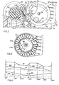
- the cylinder 44 (Fig.5) includes moreover a face cam 46 and a radial cam 48, which serve to produce the incremental rotation of the cylinder 10 to effect the basic line spacing between two successive lines of printed dots.
- the face cam 46 and the radial cam 48 include a pair of lobes 47, 47' and 49, 49' respectively which are diametrically opposed and are interposed between zero lift regions.
- a beam 50 (Figs 1 and 2) having a cam follower arm 52 held against the radial cam 48 by a spring 53 can rotate and slide axially on the shaft 12 of the writing platen.
- the beam 50 is provided with a peg 54 projecting in the direction parallel to the axis of rotation of the cylinder 44 and cooperating with the face cam 46 by virtue of the action of a helical spring 45 compressed between the beam 50 and a side 15 of the base.
- the beam 50 is moreover provided with an appendage 56 projecting parallel to the shaft 12 and having a sector 58 which is toothed at the front and selectively engaged with corresponding face toothing 60 of a wheel 62 fitted on the shaft 12.
- the cams 46, 48 are so phased relative to the groove 42 that during the constant velocity portions of the strokes of the slide 20, the face cam 46 keeps the beam 50 spaced from the wheel 62 by overcoming the action of the spring 45.
- the cam 46 releases the peg 54 of the beam 50 thereby allowing engagement between the toothed portion 58 of the beam 50 and the toothed wheel 62.
- a lobe 49 of the cam 48 (Fig 2) rotates the beam 50 anticlockwise, and the beam in turn makes the writing platen 10 rotate through an arc corresponding to one basic line spacing of the paper 16.
- the timing signals necessary for synchronising with the movement of the slide 20 the printing pulses coming through a cable 19 (Fig 1) from a logic circuit not shown in the drawings are produced by a synchronisation device comprising a small plate 71 of insulating material (Figs 2, 3) fixed to the side of the base 14 coaxially with the axis of rotation of the cylinder 64 and on which concentric conducting tracks 72, 73, 74 are deposited by a printed circuit technique.
- the track 72 is formed by an open ring 72a from which a plurality of inwardly directed radial segments 72b branch off, while the track 73 is formed by an open ring 73a within the track 72, from which a plurality of outwardly directed radial segments 73b branch off.
- the segments 72b and the segments 73b are regularly interdigitated.
- the track 74 is formed by a ring which occupies the central part of the small plate 71 and constitutes the common return for the synchronisation circuit.
- a metal lamina 78 is fixed which ends in two diametrically opposed resilient contacts 79, 80, of which the contact 79 slides alternately on the segments 72b, 73b, and the contact 80 slides on the ring 74. Consequently during the rotation of the cylinder 44 the contacts 79, 80 short circuit the segments 72b, 73b and the ring 74 in order to generate the timing signals transmitted over a cable 83 to the control logic.
- an additional radial segment 77 is disposed which is used to give a line start signal when the slide 20 is at one of the ends of the stroke.
- the segments 72b, 73b are equidistantly spaced by an arc corresponding to a step between two successive printed dots on the medium 16.
- the aforesaid arc is 11 0 15' and corresponds to a step of 0.26 mm between two dots.
- the step between two printed dots can be varied in a very simple manner without modifying the mechanical structure of the printer and without altering the logic architecture of the circuit controlling the printing head.
- the small plate 71 is interchangeable with others having a different spacing between the segments 72b, 73b.
- the small plate 71 can be removed by unscrewing a nut 70 (Fig 1) that holds it fixed to the side 15.
- the diagram SC shows the profile of the groove 42, which is intended to move the head 26, as a function of the angle of rotation of the cylinder 44
- the diagrams IN and SP relate to the profiles of cams 48 and 46 respectively provided for line spacing and axial displacement of the beam 50.
- the separation of the beam 50 from the wheel 62 occurs in a portion DIS of the diagrams IN and SP in which the lift of the cam 48 is constant, while the clockwise rotation reloading the beam 50 occurs in the succeeding portion AV in which the lift of the cam 46 is a maximum, that is, the toothing 58 of the beam 50 is completely separated from the wheel 62.
Abstract
Description
- The present invention relates to a dot matrix printer comprising a printing head movable parallel to a writing platen for selectively printing dots on a writing medium disposed on the platen and a line-spacing device comprising a toothed wheel coupled to the platen and a pawl for intermittently rotating the wheel to advance the writing medium between two successive lines of printed dots.
- Various printers of the type mentioned are known; in one of these the printing head is moved by a cam rotating about an axis perpendicular to the writing cylinder. Line spacing is obtained by means of a screw with a varying pitch which is solid with the cam and engaged with a toothed wheel coupled to the cylinder by a transmission gear. Such a printer proves to be very cumbersome for use with small computers and, because of the numerous moving parts, it is very noisy. Furthermore the line-spacing device includes a friction clutch for disengaging the line-spacing device to allow the paper tape to be advanced manually.
- The object of the present invention is to provide a dot matrix printer which is very compact, and silent, and has few moving parts and is such as to allow the paper to be advanced manually without the use of additional devices.
- The dot matrix printer according to the invention meets this object and is characterised in the manner set forth in
claim 1. - The invention will be described in more detail, by way of example, with reference to the accompanying drawings, in which:
- Fig 1 is a plan view of a printer embodying the invention;
- Fig 2 is a vertical section on a larger scale on line II-II of Fig 1;
- Fig 3 shows a synchronisation card;
- Fig 4 shows the displacement diagrams of the cams;
- Fig 5 shows a cam cylinder.
- With reference to Fig 1, the printer includes a
writing platen roller 10 fitted on ashaft 12 rotatable on abase 14. Apaper tape 16 is partly wound on theplaten 10 and is advanced during writing operations by means of incremental rotations of theplaten 10 onto which it is guided by aguide plate 18. In front of the platen 10 aslide 20 moves parallel to the axis of theplaten 10 on aguide 22. The slide comprises aflat support plate 24 on which a series- parallelthermal head 26 is fixed. - According to a particular version of the printer, the
printing head 26 is similar to that described in our Italian Patent No 1,000,641 and is formed by asmall plate 29 of ceramic material, on which twenty resistive writing elements are laid aligned along a printing line parallel to the axis of theplaten 10, for printing successions of dots on a thermosensitive layer of thepaper 16. Thesmall plate 29 is glued at itscentral region 31 to theplate 24, while at theends platen 10 by twoelastic laminae base 14 bytabs 35 and in sliding contact at oneend 37 with twopads forks plate 24 and bearing against thesmall plate 29. - The
slide 20 is moved by means of apeg 21 engaged with agroove 42 in the outer surface of acylinder 44 having its axis parallel to thewriting platen 10, and being rotated by amotor 45 through areduction gear 43. Thegroove 42 is formed by two helical arcs having constant slope but opposite directions, each extending for about 180° and being connected together with the points of reversal of the motion of theslide 20 corresponding. Consequently during a complete rotation of thecylinder 44, theslide 24 completes one forward pass and one return pass at constant velocity. Thethermal head 26 has a stroke which covers two characters which is equal to about 4mm. - The cylinder 44 (Fig.5) includes moreover a
face cam 46 and aradial cam 48, which serve to produce the incremental rotation of thecylinder 10 to effect the basic line spacing between two successive lines of printed dots. Theface cam 46 and theradial cam 48 include a pair oflobes cam follower arm 52 held against theradial cam 48 by aspring 53 can rotate and slide axially on theshaft 12 of the writing platen. Thebeam 50 is provided with apeg 54 projecting in the direction parallel to the axis of rotation of thecylinder 44 and cooperating with theface cam 46 by virtue of the action of ahelical spring 45 compressed between thebeam 50 and aside 15 of the base. - The
beam 50 is moreover provided with anappendage 56 projecting parallel to theshaft 12 and having asector 58 which is toothed at the front and selectively engaged with corresponding face toothing 60 of awheel 62 fitted on theshaft 12. - The
cams groove 42 that during the constant velocity portions of the strokes of theslide 20, theface cam 46 keeps thebeam 50 spaced from thewheel 62 by overcoming the action of thespring 45. During the phases of reversal of the motion of theslide 20, thecam 46 releases thepeg 54 of thebeam 50 thereby allowing engagement between thetoothed portion 58 of thebeam 50 and thetoothed wheel 62. At the same time alobe 49 of the cam 48 (Fig 2) rotates thebeam 50 anticlockwise, and the beam in turn makes thewriting platen 10 rotate through an arc corresponding to one basic line spacing of thepaper 16. - The timing signals necessary for synchronising with the movement of the
slide 20 the printing pulses coming through a cable 19 (Fig 1) from a logic circuit not shown in the drawings are produced by a synchronisation device comprising asmall plate 71 of insulating material (Figs 2, 3) fixed to the side of thebase 14 coaxially with the axis of rotation of the cylinder 64 and on which concentric conductingtracks track 72 is formed by an open ring 72a from which a plurality of inwardly directedradial segments 72b branch off, while thetrack 73 is formed by an open ring 73a within thetrack 72, from which a plurality of outwardly directedradial segments 73b branch off. Thesegments 72b and thesegments 73b are regularly interdigitated. - The
track 74 is formed by a ring which occupies the central part of thesmall plate 71 and constitutes the common return for the synchronisation circuit. On thebase 67 of thecylinder 44 facing the small plate 71 ametal lamina 78 is fixed which ends in two diametrically opposedresilient contacts contact 79 slides alternately on thesegments contact 80 slides on thering 74. Consequently during the rotation of thecylinder 44 thecontacts segments ring 74 in order to generate the timing signals transmitted over acable 83 to the control logic. - In the interrupted region of the
rings slide 20 is at one of the ends of the stroke. - The
segments medium 16. In accordance with a first version of the printer the aforesaid arc is 11015' and corresponds to a step of 0.26 mm between two dots. According to the printing requirements, the step between two printed dots can be varied in a very simple manner without modifying the mechanical structure of the printer and without altering the logic architecture of the circuit controlling the printing head. To obtain a varied spacing between the printed dots thesmall plate 71 is interchangeable with others having a different spacing between thesegments small plate 71 can be removed by unscrewing a nut 70 (Fig 1) that holds it fixed to theside 15. - In Fig 4 the diagram SC shows the profile of the
groove 42, which is intended to move thehead 26, as a function of the angle of rotation of thecylinder 44, while the diagrams IN and SP relate to the profiles ofcams beam 50. It is clear from these diagrams that corresponding to the phase INV (diagram SC) of reversal of the movement of theslide 20, thecam 46 has zero lift (diagram SP), and thecam 48 has an increasing lift (diagram IN), through which thebeam 50, pushed by thespring 45, is engaged with thewheel 62 while thelobe 49 of thecam 48 rotates thebeam 50 to advance thewriting medium 16 by one line space. - The separation of the
beam 50 from thewheel 62 occurs in a portion DIS of the diagrams IN and SP in which the lift of thecam 48 is constant, while the clockwise rotation reloading thebeam 50 occurs in the succeeding portion AV in which the lift of thecam 46 is a maximum, that is, thetoothing 58 of thebeam 50 is completely separated from thewheel 62. - In such circumstances the angular position reached by the
platen 10 after each line spacing is no longer affected by successive movements of the beam, thus ensuring constant spacing between the lines of printed dots. - Furthermore in the portion AV, since the
platen 10 is completely disengaged from the line spacing device, can be rotated manually to advance thepaper tape 16.
Claims (7)
Applications Claiming Priority (2)
| Application Number | Priority Date | Filing Date | Title |
|---|---|---|---|
| IT6820583 | 1983-11-18 | ||
| IT68205/83A IT1159628B (en) | 1983-11-18 | 1983-11-18 | REFINEMENTS FOR A POINT PRINTER |
Publications (3)
| Publication Number | Publication Date |
|---|---|
| EP0144153A2 true EP0144153A2 (en) | 1985-06-12 |
| EP0144153A3 EP0144153A3 (en) | 1987-12-02 |
| EP0144153B1 EP0144153B1 (en) | 1990-07-25 |
Family
ID=11308481
Family Applications (1)
| Application Number | Title | Priority Date | Filing Date |
|---|---|---|---|
| EP84307545A Expired EP0144153B1 (en) | 1983-11-18 | 1984-11-01 | Dot matrix printer |
Country Status (5)
| Country | Link |
|---|---|
| EP (1) | EP0144153B1 (en) |
| JP (1) | JPS60137677A (en) |
| DE (1) | DE3482821D1 (en) |
| ES (1) | ES537737A0 (en) |
| IT (1) | IT1159628B (en) |
Cited By (1)
| Publication number | Priority date | Publication date | Assignee | Title |
|---|---|---|---|---|
| CN100526082C (en) * | 2006-04-28 | 2009-08-12 | 光宝科技股份有限公司 | Driving module for driving print-head maintaining device |
Citations (5)
| Publication number | Priority date | Publication date | Assignee | Title |
|---|---|---|---|---|
| US3394853A (en) * | 1966-10-10 | 1968-07-30 | Thomas P. Foley | Timing disc for high speed printers |
| US3602355A (en) * | 1968-06-01 | 1971-08-31 | Olympia Werke Ag | Apparatus for intermittent transport of a record carrier |
| US3628713A (en) * | 1969-01-29 | 1971-12-21 | Honeywell Bull Soc Ind | Mechanism for the step-by-step transport of documents |
| US3826915A (en) * | 1971-09-06 | 1974-07-30 | Olivetti & Co Spa | Non-impact printing device for electronic calculators |
| US4401391A (en) * | 1980-04-28 | 1983-08-30 | Matsushita Electric Industrial Co., Ltd. | Serial printer |
Family Cites Families (1)
| Publication number | Priority date | Publication date | Assignee | Title |
|---|---|---|---|---|
| JPS60986A (en) * | 1983-06-17 | 1985-01-07 | Matsushita Electric Ind Co Ltd | Paper feed apparatus |
-
1983
- 1983-11-18 IT IT68205/83A patent/IT1159628B/en active
-
1984
- 1984-11-01 EP EP84307545A patent/EP0144153B1/en not_active Expired
- 1984-11-01 DE DE8484307545T patent/DE3482821D1/en not_active Expired - Lifetime
- 1984-11-16 ES ES537737A patent/ES537737A0/en active Granted
- 1984-11-19 JP JP59244328A patent/JPS60137677A/en active Granted
Patent Citations (5)
| Publication number | Priority date | Publication date | Assignee | Title |
|---|---|---|---|---|
| US3394853A (en) * | 1966-10-10 | 1968-07-30 | Thomas P. Foley | Timing disc for high speed printers |
| US3602355A (en) * | 1968-06-01 | 1971-08-31 | Olympia Werke Ag | Apparatus for intermittent transport of a record carrier |
| US3628713A (en) * | 1969-01-29 | 1971-12-21 | Honeywell Bull Soc Ind | Mechanism for the step-by-step transport of documents |
| US3826915A (en) * | 1971-09-06 | 1974-07-30 | Olivetti & Co Spa | Non-impact printing device for electronic calculators |
| US4401391A (en) * | 1980-04-28 | 1983-08-30 | Matsushita Electric Industrial Co., Ltd. | Serial printer |
Cited By (1)
| Publication number | Priority date | Publication date | Assignee | Title |
|---|---|---|---|---|
| CN100526082C (en) * | 2006-04-28 | 2009-08-12 | 光宝科技股份有限公司 | Driving module for driving print-head maintaining device |
Also Published As
| Publication number | Publication date |
|---|---|
| ES8601617A1 (en) | 1985-10-16 |
| EP0144153B1 (en) | 1990-07-25 |
| ES537737A0 (en) | 1985-10-16 |
| EP0144153A3 (en) | 1987-12-02 |
| JPS60137677A (en) | 1985-07-22 |
| DE3482821D1 (en) | 1990-08-30 |
| IT1159628B (en) | 1987-03-04 |
| IT8368205A0 (en) | 1983-11-18 |
| JPH0551468B2 (en) | 1993-08-02 |
Similar Documents
| Publication | Publication Date | Title |
|---|---|---|
| US3356199A (en) | Printer having type disk rotatable in a plane parallel to the printing line | |
| US3332343A (en) | Selective hammer interposing means in high speed printers | |
| JPS6126051Y2 (en) | ||
| US3236351A (en) | High speed matrix printer | |
| US4235555A (en) | Non impact dot matrix printer | |
| US3826915A (en) | Non-impact printing device for electronic calculators | |
| US4573814A (en) | Dot matrix printer | |
| US3166752A (en) | Page printing device utilizing a scanning electrode structure | |
| US3352398A (en) | Character selection mechanism without return to home position | |
| EP0144153B1 (en) | Dot matrix printer | |
| US4379646A (en) | Paper feed roll rotated by print head carrier movement | |
| EP0150100A2 (en) | A ribbon lifting device for a printer | |
| GB1138502A (en) | Programming apparatus | |
| US4420763A (en) | Electromechanical printing device for a printer of the series-parallel type | |
| US4500217A (en) | Electronic printer mechanism with movable printhead assembly | |
| US4392424A (en) | Belt printing mechanism having improved catch mechanism for detenting positioning wheel | |
| JPH0223356B2 (en) | ||
| US3763986A (en) | Data recording | |
| US3106620A (en) | Cam actuated switch | |
| EP0382353A2 (en) | Cursor control mechanism | |
| US3967715A (en) | Intermittent drive system for typewriters | |
| US2429659A (en) | Switching apparatus with periodically operated contacts | |
| US4365550A (en) | Printing mechanism for dot matrix printers | |
| US3926295A (en) | Hammerless impact printer | |
| US3643263A (en) | Reciprocating system for recording assembly |
Legal Events
| Date | Code | Title | Description |
|---|---|---|---|
| PUAI | Public reference made under article 153(3) epc to a published international application that has entered the european phase |
Free format text: ORIGINAL CODE: 0009012 |
|
| AK | Designated contracting states |
Designated state(s): DE FR GB |
|
| PUAL | Search report despatched |
Free format text: ORIGINAL CODE: 0009013 |
|
| AK | Designated contracting states |
Kind code of ref document: A3 Designated state(s): DE FR GB |
|
| 17P | Request for examination filed |
Effective date: 19880406 |
|
| 17Q | First examination report despatched |
Effective date: 19890224 |
|
| GRAA | (expected) grant |
Free format text: ORIGINAL CODE: 0009210 |
|
| AK | Designated contracting states |
Kind code of ref document: B1 Designated state(s): DE FR GB |
|
| REF | Corresponds to: |
Ref document number: 3482821 Country of ref document: DE Date of ref document: 19900830 |
|
| ET | Fr: translation filed | ||
| PLBE | No opposition filed within time limit |
Free format text: ORIGINAL CODE: 0009261 |
|
| STAA | Information on the status of an ep patent application or granted ep patent |
Free format text: STATUS: NO OPPOSITION FILED WITHIN TIME LIMIT |
|
| 26N | No opposition filed | ||
| PGFP | Annual fee paid to national office [announced via postgrant information from national office to epo] |
Ref country code: GB Payment date: 19921021 Year of fee payment: 9 |
|
| PGFP | Annual fee paid to national office [announced via postgrant information from national office to epo] |
Ref country code: FR Payment date: 19921109 Year of fee payment: 9 |
|
| PGFP | Annual fee paid to national office [announced via postgrant information from national office to epo] |
Ref country code: DE Payment date: 19921123 Year of fee payment: 9 |
|
| PG25 | Lapsed in a contracting state [announced via postgrant information from national office to epo] |
Ref country code: GB Effective date: 19931101 |
|
| GBPC | Gb: european patent ceased through non-payment of renewal fee |
Effective date: 19931101 |
|
| PG25 | Lapsed in a contracting state [announced via postgrant information from national office to epo] |
Ref country code: FR Effective date: 19940729 |
|
| PG25 | Lapsed in a contracting state [announced via postgrant information from national office to epo] |
Ref country code: DE Effective date: 19940802 |
|
| REG | Reference to a national code |
Ref country code: FR Ref legal event code: ST |