EP0143851B1 - Turning controller for z-type propulsion device - Google Patents
Turning controller for z-type propulsion device Download PDFInfo
- Publication number
- EP0143851B1 EP0143851B1 EP84901408A EP84901408A EP0143851B1 EP 0143851 B1 EP0143851 B1 EP 0143851B1 EP 84901408 A EP84901408 A EP 84901408A EP 84901408 A EP84901408 A EP 84901408A EP 0143851 B1 EP0143851 B1 EP 0143851B1
- Authority
- EP
- European Patent Office
- Prior art keywords
- speed
- rotation
- propeller
- output
- angle
- Prior art date
- Legal status (The legal status is an assumption and is not a legal conclusion. Google has not performed a legal analysis and makes no representation as to the accuracy of the status listed.)
- Expired - Lifetime
Links
Images


Classifications
-
- G—PHYSICS
- G05—CONTROLLING; REGULATING
- G05D—SYSTEMS FOR CONTROLLING OR REGULATING NON-ELECTRIC VARIABLES
- G05D1/00—Control of position, course, altitude or attitude of land, water, air or space vehicles, e.g. using automatic pilots
- G05D1/02—Control of position or course in two dimensions
- G05D1/0206—Control of position or course in two dimensions specially adapted to water vehicles
-
- B—PERFORMING OPERATIONS; TRANSPORTING
- B63—SHIPS OR OTHER WATERBORNE VESSELS; RELATED EQUIPMENT
- B63H—MARINE PROPULSION OR STEERING
- B63H25/00—Steering; Slowing-down otherwise than by use of propulsive elements; Dynamic anchoring, i.e. positioning vessels by means of main or auxiliary propulsive elements
- B63H25/42—Steering or dynamic anchoring by propulsive elements; Steering or dynamic anchoring by propellers used therefor only; Steering or dynamic anchoring by rudders carrying propellers
-
- Y—GENERAL TAGGING OF NEW TECHNOLOGICAL DEVELOPMENTS; GENERAL TAGGING OF CROSS-SECTIONAL TECHNOLOGIES SPANNING OVER SEVERAL SECTIONS OF THE IPC; TECHNICAL SUBJECTS COVERED BY FORMER USPC CROSS-REFERENCE ART COLLECTIONS [XRACs] AND DIGESTS
- Y10—TECHNICAL SUBJECTS COVERED BY FORMER USPC
- Y10T—TECHNICAL SUBJECTS COVERED BY FORMER US CLASSIFICATION
- Y10T74/00—Machine element or mechanism
- Y10T74/20—Control lever and linkage systems
- Y10T74/20207—Multiple controlling elements for single controlled element
- Y10T74/20213—Interconnected
- Y10T74/20232—Marine
Definitions
- This invention relates to a turning controller for a Z-type propulsion apparatus for use in a vessel such as a tug boat.
- a Z-type propulsion apparatus which can easily vary the direction of propulsion over the range of 360 degrees.
- a Z-type propulsion apparatus for example, shown in Fig. 1, the rotation of a main engine 1 is transmitted to an input shaft 6 via a universal joint 3, an intermediate shaft 4 and a universal joint 5 when a clutch 2 is connected, and the rotation of the input shaft 6 is transmitted to a propeller 12 attached to a propeller shaft 11 via bevel gears 7, 8, 9 and 10 so that the propeller 12 is rotated to advance the vessel.
- a hydraulic motor 14 controlled by a rotation control unit 13 is transmitted to a hollow rotary housing 17 via a worm gear 15 and a worm wheel 16 to angularly move the rotary housing 17 so that the direction of propulsion of the propeller 12 is changed to turn the vessel.
- One conventional method of controlling the rotation of the Z-type propulsion apparatus is to control the speed of rotation of the hydraulic motor 14 with respect to the speed of rotation of the main engine 1.
- the main engine 1 drives a hydraulic pump so as to control the hydraulic motor 14.
- a motor drives the hydraulic pump to control the hydraulic motor 14.
- the speed of rotation of the main engine 1 is detected and the angle of inclination of the hydraulic pump is controlled to be in inverse proportion to the speed of rotation of the main engine 1 so that the speed of rotation of the hydraulic motor 14 becomes constant.
- the speed of rotation of the hydraulic motor 14 is detected and the angle of inclination of the hydraulic pump is controlled so that the speed of rotation of the hydraulic motor 14 becomes constant.
- the speed of rotation of the rotary housing is decreased to prevent an increase in the hydraulic drive force and an abrupt turning of the vessel when the speed of rotation of the main engine 1 is high.
- the speed of rotation of the main engine 1 is low, the speed of rotation of the rotary housing is increased to make use of the surplus of the hydraulic drive force and to rapidly turn the vessel.
- vessels provided with such a Z-type propulsion apparatus are mostly used as tug boats.
- the speed of rotation of the main engine 1 is not always proportional to the speed of the boat or the number of revolution of the propeller. There are occasions when the speed of rotation of the main engine 1 is low while the speed of the boat is high and occasions when the speed of rotation of the main engine 1 is high while the speed of the boat is low.
- the motor for driving the hydraulic pump is subjected to overload and is stopped by a safety device and also the hydraulic pump is damaged when the rotation of the main engine 1 is low while the speed of the boat is high (when the tug boat is tugged by the vessel). Also, when the speed of rotation of the main engine is high while the speed of the boat is low (when the tug boat tugs the vessel), a high speed of turning can not be achieved.
- FIG. 2 Another known rotation control system for controlling the turning of a vessel equipped with the Z-type propulsion apparatus is shown in Fig. 2.
- This system comprises a steering angle detector 22 for detecting the steering angle of a steering handle 21 for rotating a hollow rotary housing of the Z-type propulsion apparatus, a rotation angle detector 23 for detecting the rotation angle (follow-up angle) of the rotary housing 17, an error voltage generator 24 for comparing a detected value 01 of the steering angle detector 22 with a detected value 82 of the rotation angle detector 23 to output an error voltage, a rotation speed detector 25 for detecting the speed of rotation of the rotary housing 17, a servo circuit 26 for comparing the output of the error voltage generator 24 with the output of the rotation speed detector 25 to output a servo signal, a flow rate and direction control valve 27 such as an electromagnetic proportional control valve controlled by the servo signal, a hydraulic pump 29 connected to the flow rate and direction control valve 27 and driven by a motor 28, and a hydraulic motor 14 connected to the flow rate and direction control valve 27 and
- the error voltage generator 24 generates a voltage increasing in propottion to a difference of angle ( ⁇ 1-- ⁇ 2) when -A (A is a positive constant value) ⁇ difference of angle (01 -02) ⁇ A is provided, and also it generates a negative or a positive constant voltage when the difference of angle ( ⁇ 1- ⁇ 2) ⁇ -A or the difference of angle (81-82) ?A is provided. Therefore, the servo circuit 26 controls the flow rate and direction control valve 27 so that the voltage generated by the error voltage generator 24 coincides with the output of the rotation speed detector 25. As a result, the hydraulic motor 14 is operated in accordance with the output of the error voltage generator 24 to rotate the rotary housing 17.
- the speed of rotation of the rotary housing is controlled in accordance with the error voltage shown in Fig. 3 irrespective of the speed of the vessel, and is always constant except when the difference of angle ( ⁇ 1-- ⁇ 2) is in the vicinity of 0. Therefore, even if the steering handle 21 is angularly moved at the same angle, the turning of the vessel is varied depending on the speed of the vessel. More specifically, when the speed of the vessel is high, the vessel is turned at a high speed. This is dangerous. And, when the speed of the vessel is low, the turning speed is lowered so that a small turn can not be achieved, thereby affecting a steering performance of the vessel. Therefore, with the conventional system, the operator must change the manner of steering the steering handle 21 in accordance with the speed of the vessel. Thus, the steering operation is difficult and much skill is required.
- the apparatus of the present invention is defined in claim 1. Such an apparatus is capable of steering a vessel to achieve an optimum turn irrespective of the speed of the vessel and enhances the ability of high speed turning of the vessel.
- Embodiments of the apparatus are capable of controlling a plurality of Z-type propulsion apparatuses mounted on a vessel such as a multi- shaft vessel and are capable of steering the vessel to achieve an optimum turn.
- Reference number 14 designates a hydraulic motor which is connected to a worm wheel 16 via a worm 15 formed in a worm shaft 30, the worm wheel 16 being connected to a hollow rotary housing 17 of a Z-type propulsion apparatus.
- a tachometer (rotation speed detector) 25 is connected to the worm shaft 30 which is connected via gears 31 and 32 to a follow-up potentiometer 23 (rotation angle detector).
- a propeller revolution detector 60 for detecting the rate of revolution of the propeller 12 is mounted on a vertical shaft 59 which connects bevel gears 7 and 8 together.
- the output of the rotation angle detector 23 is connected to one input terminal of an error voltage generator 24.
- a steering angle detector 22 Connected to the other input terminal of the error voltage generator 24 is a steering angle detector 22 for detecting the steering angle of a steering handle 21 which causes a rotary housing 17 to be rotated.
- the error voltage in accordance with a difference (61-62) (difference of angle) between the detection value 61 of the steering angle detector 22 and the detection value 82 of the rotation angle detector 23.
- the error voltage generator 24 is connected to one input terminal of a variable limiter circuit 61, and the output terminal of the propeller revolution detector 60 is connected to the other input terminal of the variable limiter circuit 61.
- the variable limiter circuit 61 is designed to limit the output of the error voltage generator 24 in accordance with the output of the propeller revolution detector 60. Also, the output terminal of the variable limiter circuit 61 is connected to one input terminal of a servo circuit 62, and an output terminal of a rotation speed detector 25 is connected to the other input terminal of the servo circuit 62.
- the servo circuit 62 is designed to output a servo signal to a flow rate and direction control valve 48 such as an electromagnetic proportional control valve so that the output of the variable limiter circuit 61 coincides with the detection value of the rotation speed detector 25.
- the flow rate and direction control valve 48 is connected to a hydraulic motor 14 via pipes 63 and 64, and to a hydraulic pump 66 via a pipe 65 and to an oil tank 68 via a pipe 67.
- the hydraulic pump 66 and the oil tank 68 are connected together by a pipe 69, and a motor 70 is connected to the hydraulic pump 66.
- the main engine 1 is rotated, and a clutch 2 is connected, so that the rotation of the main engine 1 is transmitted to an input shaft 6 via a universal joint 3, an intermediate shaft 4 and a universal joint 5.
- the rotation of the input shaft 6 is transmitted to a propeller shaft 11 via bevel gears 7 and 8, the vertical shaft 59 and bevel gears 9 and 10 so that the propeller 12 is rotated to advance the vessel.
- the steering angle detector 22 outputs a detection value 01 representative of the steering angle to the error voltage generator 24.
- the detection value 82 of the rotation angle detector 23 is "0".
- the error voltage generator 24 produces an error voltage in accordance with the difference (61-62) (difference of angle) between the detection value 01 of the steering angle detector 22 and the detection value 62 of the rotation angle detector 23, this error voltage being similar to that produced by the conventional error voltage generator 24 in Fig. 3.
- the error voltage produced by the error voltage generator 24 is limited by the variable limiter circuit 61 in accordance with the output of the propeller revolution detector 60. As the number of revolution of the propeller varies from a small value Na (i.e., the speed of the vessel is low) to a greater value Nb (i.e., the speed of the vessel is high), the maximum and minimum values of the error voltage are restricted as shown in Fig. 5.
- the absolute value of the output of the variable limiter circuit 61 at the same difference of angle (61 -62) becomes smaller.
- the output of the variable limiter circuit 61 is inputted to the servo circuit 62, and the flow rate and direction control valve 48 is controlled by the output (servo signal) of the servo circuit 62, so that the amount of feed of oil from the hydraulic pump 66 to the hydraulic motor 14 as well as the direction of feed of oil is controlled. Therefore, the hydraulic motor 14 is rotated in the thus selected direction at a speed determined by the amount of feed of oil to thereby rotate the rotary housing 17.
- the detection value of the rotation speed detector 25 is inputted to the servo circuit 62, so that the servo circuit 62 outputs the servo signal to the flow rate and direction control valve 48 so as to cause the output of the variable limiter circuit 61 to coincide with the speed of rotation of the rotary housing 17.
- the speed of rotation of the rotary housing 17 coincides with the output of the variable limiter circuit 61, and the rotary housing 17 continues to rotate in this condition.
- the detection value 82 of the rotation angle detector 23 becomes greater in accordance with the rotation of the rotary housing 17 and is inputted to the error voltage generator 24, so that the difference of angle (61-62) becomes smaller gradually.
- the flow rate and direction control valve 48 is controlled by the servo signal of the servo circuit 62 to stop the feed of oil from the hydraulic pump 66 to the hydraulic motor 14, so that the rotation of the hydraulic motor 14 is stopped to stop the rotary housing 17.
- the rotary housing 17 is rotated in accordance with the steering angle of the steering handle 21.
- the variable limiter circuit 61 controls the output. Therefore, as shown in Fig. 10, when the number N of revolution of the propeller is great (i.e., the speed of the vessel is high), the speed Vr of rotation of the rotary housing 17 becomes small. On the other hand, when the number N of revolution of the propeller is small (i.e., the speed of the vessel is low), the speed Vr of the rotary housing 17 becomes greater.
- Each of the rotation angle detector 23 and the steering angle detector 22 may be of any type such as a potentiometer, a synchro and an angle detector of the optical type so long as it can detect an angle.
- each of the rotation speed detector 25 and the propeller revolution detector 60 may be of any type such as a magnet disc and a tachometer generator so long as it can detect the speed of rotation.
- the propeller of each propulsion device is driven by an individual main engine, and therefore the numbers of revolution of the propellers are different from one another.
- the speeds of rotation of the rotary housings are not in synchronism with one another, and therefore it is possible that the vessel is directed in a direction different from that intended by the steering operation.
- error voltage generators 241 and 24r When a pair of steering handles 211 and 21 r are angularly moved to turn the vessel during the advancing of the vessel, error voltage generators 241 and 24r output error voltages to the variable limiter circuits 611 and 61r in accordance with a difference ( ⁇ '1- ⁇ '2) between the detection value ⁇ '1 of a steering angle detector 221 and the detection value ⁇ '2 of a rotation angle detector 231 and a difference ( ⁇ "1- ⁇ "2) between the detection value 6"1 of a steering angle detector 22r and the detection value 0"2 of a rotation angle detector 23r, as described above for the error voltage generator in Fig. 3.
- the maximum value selection circuit 80 to which the rate of revolution of the propellers detected by the propeller revolution detectors 601 and 60r are inputted selects the maximum value of these revolution numbers and outputs a signal representative thereof to the respective variable limiter circuits 611 and 61 r.
- the variable limiter circuits 611 and 61 r limit the outputs (error voltages) of the error voltage generators 241 and 24r in accordance with the output of the maximum value selection circuit 80 representative of the maximum value of the number of revolution of the propellers.
- variable limiter circuits 611 and 61 r are limited by the same value, i.e., the maximum value of the rates of revolution of the propellers, and therefore the variable limiter circuits 611 and 61 r feed voltage to the respective servo circuit 621 and 62r in accordance with the same output curve. Therefore, the maximum and minimum values of the outputs of the variable limiter circuits 611 and 61 r are limited as shown in Fig. 5.
- the servo circuit 621 and 62r to which the outputs of the respective variable limiter circuits 611 and 61 r have been inputted output the servo signals to control the respective flow rate and direction control valves 481 and 48r, so that the respective hydraulic motors 141 and 14r are rotated to rotate the respective rotary housings 171 and 17r.
- the detection values of rotation speed detectors 251 and 25r are inputted to the respective servo circuits 621 and 62r which in turn output servo signals to the respective flow rate and direction control valves 481 and 48r so as to cause the speeds of rotation of the rotary housings 171 and 17r to coincide with the outputs of the respective variable limiter circuits 611 and 61r.
- the speeds of rotation of the rotary housings 171 and 17r coincide with the outputs of the respective variable limiter circuits 611 and 61r r controlled by the output of the maximum value selection circuit 80, and the rotary housings 171 and 17r continues to rotate.
- the detection values 6'2 and 6"2 of the rotation angle detectors 231 and 23r approach the detection values 0'1 and 8"1 of the steering angle detectors 221 and 22r in accordance with the rotations of the rotary housings 171 and 17r, so that the differences of angle ( ⁇ '1- ⁇ '2) and (0"1-0"2) become smaller gradually. Then, when the detection values 8'1 and 6"1 of the steering angle detectors 221 and 22r coincide with the detection values 8'2 and ⁇ "2 of the rotation angle detectors 231 and 23r, respectively, the differences of angle ( ⁇ '1- ⁇ '2) and ( ⁇ "1- ⁇ "2) are rendered "0", and the outputs of the error voltage generators 241 and 24r are rendered "0".
- variable limiter circuits 611 and 61r are rendered "0".
- the flow rate and direction control valves 481 and 48r are controlled by the servo signals of the servo circuits 621 and 62r to stop the hydraulic motors 141 and 14r so that the rotations of the rotary housings 171 and 17r are stopped.
- the rotary housings 171 and 17r are rotated in accordance with the steering angles of the steering handles 211 and 21 r, respectively.
- variable limiter circuits 611 and 61r r limit their respective outputs in accordance with the output (the maximum value of the numbers of revolution of the propellers) of the maximum value selection circuit 80, so that the speeds of rotation of the rotary housings 171 and 17r synchronize each other. Therefore, when the output of the maximum value selection circuit 80 is great, the speeds of rotation of the rotary housings 171 and 17r are low. On the other hand, when the output of the maximum value selection circuit 80 is small, the speeds of rotation of the rotary housings 171 and 17r are high.
- the rotary housing 171 and 17r are rotated in synchronism with each other in accordance with the output of the maximum value selection circuit 80.
- This embodiment has been described with reference to the vessel having the pair of propulsion apparatuses, but this invention can be applied to a vessel having more than two Z-type propulsion apparatuses.
- the detection signal representative of the number of revolution of each of the propellers is used for limiting the error voltage, it may be replaced by a signal representing the rate of revolution of each of other parts such as the main engines and the propeller drive shaft systems.
- the present invention can be quite advantageous where a vessel such as a tug boat is required to make a small turn quickly and where the vessel, subjected to a force from another vessel, is turned.
Landscapes
- Engineering & Computer Science (AREA)
- Physics & Mathematics (AREA)
- Chemical & Material Sciences (AREA)
- Mechanical Engineering (AREA)
- Ocean & Marine Engineering (AREA)
- Aviation & Aerospace Engineering (AREA)
- Radar, Positioning & Navigation (AREA)
- Combustion & Propulsion (AREA)
- General Physics & Mathematics (AREA)
- Remote Sensing (AREA)
- Automation & Control Theory (AREA)
- Operation Control Of Excavators (AREA)
- Control Of Velocity Or Acceleration (AREA)
- Control Of Throttle Valves Provided In The Intake System Or In The Exhaust System (AREA)
- Fluid-Pressure Circuits (AREA)
- Non-Deflectable Wheels, Steering Of Trailers, Or Other Steering (AREA)
Abstract
Description
- This invention relates to a turning controller for a Z-type propulsion apparatus for use in a vessel such as a tug boat.
- In recent years, harbors have become much crowded with vessels of a large size, and therefore it has been required that tug boats should operate to move vessels toward and away from the shore in a safe and rapid manner. For this reason, there have now been extensively used tug boats equipped with a Z-type propulsion apparatus which can easily vary the direction of propulsion over the range of 360 degrees. In such a Z-type propulsion apparatus, for example, shown in Fig. 1, the rotation of a main engine 1 is transmitted to an input shaft 6 via a
universal joint 3, anintermediate shaft 4 and auniversal joint 5 when a clutch 2 is connected, and the rotation of the input shaft 6 is transmitted to a propeller 12 attached to a propeller shaft 11 viabevel gears hydraulic motor 14 controlled by arotation control unit 13 is transmitted to a hollowrotary housing 17 via aworm gear 15 and aworm wheel 16 to angularly move therotary housing 17 so that the direction of propulsion of the propeller 12 is changed to turn the vessel. - One conventional method of controlling the rotation of the Z-type propulsion apparatus is to control the speed of rotation of the
hydraulic motor 14 with respect to the speed of rotation of the main engine 1. In such a conventional method, the main engine 1 drives a hydraulic pump so as to control thehydraulic motor 14. Alternatively, a motor drives the hydraulic pump to control thehydraulic motor 14. In the method in which the main engine 1 drives the hydraulic pump, the speed of rotation of the main engine 1 is detected and the angle of inclination of the hydraulic pump is controlled to be in inverse proportion to the speed of rotation of the main engine 1 so that the speed of rotation of thehydraulic motor 14 becomes constant. Alternatively, the speed of rotation of thehydraulic motor 14 is detected and the angle of inclination of the hydraulic pump is controlled so that the speed of rotation of thehydraulic motor 14 becomes constant. - Among these control methods, in the case where the vessel is equipped with the Z-type propulsion apparatus of the type by which a turning force exerted on the vessel is proportional to the square of the speed of travel of the vessel, it might be considered that the speed of rotation of the rotary housing is decreased to prevent an increase in the hydraulic drive force and an abrupt turning of the vessel when the speed of rotation of the main engine 1 is high. On the other hand, it might also be considered that when the speed of rotation of the main engine 1 is low, the speed of rotation of the rotary housing is increased to make use of the surplus of the hydraulic drive force and to rapidly turn the vessel.
- However, vessels provided with such a Z-type propulsion apparatus are mostly used as tug boats. In the case where the tug boat has to carry out the mooring of a vessel, the speed of rotation of the main engine 1 is not always proportional to the speed of the boat or the number of revolution of the propeller. There are occasions when the speed of rotation of the main engine 1 is low while the speed of the boat is high and occasions when the speed of rotation of the main engine 1 is high while the speed of the boat is low. Therefore, in the method of controlling the speed of rotation of the rotary housing merely in inverse proportion to the speed of rotation of the main engine 1, the motor for driving the hydraulic pump is subjected to overload and is stopped by a safety device and also the hydraulic pump is damaged when the rotation of the main engine 1 is low while the speed of the boat is high (when the tug boat is tugged by the vessel). Also, when the speed of rotation of the main engine is high while the speed of the boat is low (when the tug boat tugs the vessel), a high speed of turning can not be achieved.
- Another known rotation control system for controlling the turning of a vessel equipped with the Z-type propulsion apparatus is shown in Fig. 2. This system comprises a
steering angle detector 22 for detecting the steering angle of asteering handle 21 for rotating a hollow rotary housing of the Z-type propulsion apparatus, arotation angle detector 23 for detecting the rotation angle (follow-up angle) of therotary housing 17, anerror voltage generator 24 for comparing a detected value 01 of thesteering angle detector 22 with a detectedvalue 82 of therotation angle detector 23 to output an error voltage, arotation speed detector 25 for detecting the speed of rotation of therotary housing 17, aservo circuit 26 for comparing the output of theerror voltage generator 24 with the output of therotation speed detector 25 to output a servo signal, a flow rate anddirection control valve 27 such as an electromagnetic proportional control valve controlled by the servo signal, ahydraulic pump 29 connected to the flow rate anddirection control valve 27 and driven by amotor 28, and ahydraulic motor 14 connected to the flow rate anddirection control valve 27 and adapted to rotate therotary housing 17 via aworm gear 15 and aworm wheel 16. As shown in Fig. 3, theerror voltage generator 24 generates a voltage increasing in propottion to a difference of angle (θ1--θ2) when -A (A is a positive constant value) < difference of angle (01 -02) < A is provided, and also it generates a negative or a positive constant voltage when the difference of angle (θ1-θ2)≦-A or the difference of angle (81-82) ?A is provided. Therefore, theservo circuit 26 controls the flow rate anddirection control valve 27 so that the voltage generated by theerror voltage generator 24 coincides with the output of therotation speed detector 25. As a result, thehydraulic motor 14 is operated in accordance with the output of theerror voltage generator 24 to rotate therotary housing 17. - However, in the above-mentioned rotation control system, the speed of rotation of the rotary housing is controlled in accordance with the error voltage shown in Fig. 3 irrespective of the speed of the vessel, and is always constant except when the difference of angle (θ1--θ2) is in the vicinity of 0. Therefore, even if the
steering handle 21 is angularly moved at the same angle, the turning of the vessel is varied depending on the speed of the vessel. More specifically, when the speed of the vessel is high, the vessel is turned at a high speed. This is dangerous. And, when the speed of the vessel is low, the turning speed is lowered so that a small turn can not be achieved, thereby affecting a steering performance of the vessel. Therefore, with the conventional system, the operator must change the manner of steering thesteering handle 21 in accordance with the speed of the vessel. Thus, the steering operation is difficult and much skill is required. - In US-A-3715571 there is described a ship's steering system in which, in order to control heel in turning, the ship's speed and rate-of-turn are measured and multiplied in a computer, the output of the computer being used to modify the characteristics of a summing amplifier through which rudder control signals are applied to the steering mechanism.
- The apparatus of the present invention is defined in claim 1. Such an apparatus is capable of steering a vessel to achieve an optimum turn irrespective of the speed of the vessel and enhances the ability of high speed turning of the vessel.
- Embodiments of the apparatus are capable of controlling a plurality of Z-type propulsion apparatuses mounted on a vessel such as a multi- shaft vessel and are capable of steering the vessel to achieve an optimum turn.
- Prior art turning controllers have been described and embodiments of the invention will now be described, by way of example only, with reference to the accompanying diagrammatic drawings, in which:
- Fig. 1 is a block diagram of a conventional rotation control system for a Z-type propulsion apparatus;
- Fig. 2 is a block diagram of another conventional rotation control system;
- Fig. 3 is an illustration showing characteristics of the operation of the control system of Fig. 2;
- Fig. 4.is a block diagram of a first embodiment of this invention;
- Figs. 5 and 6 are illustrations showing characteristics of the operation of the system of Fig. 4; and
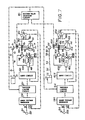
- Fig. 7 is a block diagram of a second embodiment of this invention.
-
Reference number 14 designates a hydraulic motor which is connected to aworm wheel 16 via aworm 15 formed in aworm shaft 30, theworm wheel 16 being connected to a hollowrotary housing 17 of a Z-type propulsion apparatus. A tachometer (rotation speed detector) 25 is connected to theworm shaft 30 which is connected viagears 31 and 32 to a follow-up potentiometer 23 (rotation angle detector). - A
propeller revolution detector 60 for detecting the rate of revolution of the propeller 12 is mounted on a vertical shaft 59 which connects bevel gears 7 and 8 together. - The output of the
rotation angle detector 23 is connected to one input terminal of anerror voltage generator 24. Connected to the other input terminal of theerror voltage generator 24 is asteering angle detector 22 for detecting the steering angle of asteering handle 21 which causes arotary housing 17 to be rotated. The error voltage in accordance with a difference (61-62) (difference of angle) between the detection value 61 of thesteering angle detector 22 and thedetection value 82 of therotation angle detector 23. Theerror voltage generator 24 is connected to one input terminal of a variable limiter circuit 61, and the output terminal of thepropeller revolution detector 60 is connected to the other input terminal of the variable limiter circuit 61. The variable limiter circuit 61 is designed to limit the output of theerror voltage generator 24 in accordance with the output of thepropeller revolution detector 60. Also, the output terminal of the variable limiter circuit 61 is connected to one input terminal of aservo circuit 62, and an output terminal of arotation speed detector 25 is connected to the other input terminal of theservo circuit 62. Theservo circuit 62 is designed to output a servo signal to a flow rate anddirection control valve 48 such as an electromagnetic proportional control valve so that the output of the variable limiter circuit 61 coincides with the detection value of therotation speed detector 25. - The flow rate and
direction control valve 48 is connected to ahydraulic motor 14 viapipes pipe 69, and a motor 70 is connected to the hydraulic pump 66. - The operation of this rotation control system will now be described.
- First, the main engine 1 is rotated, and a clutch 2 is connected, so that the rotation of the main engine 1 is transmitted to an input shaft 6 via a
universal joint 3, anintermediate shaft 4 and auniversal joint 5. The rotation of the input shaft 6 is transmitted to a propeller shaft 11 via bevel gears 7 and 8, the vertical shaft 59 andbevel gears steering handle 21 is angularly moved, thesteering angle detector 22 outputs a detection value 01 representative of the steering angle to theerror voltage generator 24. At this time, since the rotary housing has not yet been rotated, thedetection value 82 of therotation angle detector 23 is "0". Then, theerror voltage generator 24 produces an error voltage in accordance with the difference (61-62) (difference of angle) between the detection value 01 of thesteering angle detector 22 and thedetection value 62 of therotation angle detector 23, this error voltage being similar to that produced by the conventionalerror voltage generator 24 in Fig. 3. The error voltage produced by theerror voltage generator 24 is limited by the variable limiter circuit 61 in accordance with the output of thepropeller revolution detector 60. As the number of revolution of the propeller varies from a small value Na (i.e., the speed of the vessel is low) to a greater value Nb (i.e., the speed of the vessel is high), the maximum and minimum values of the error voltage are restricted as shown in Fig. 5. Therefore, as the speed of the vessel becomes higher, the absolute value of the output of the variable limiter circuit 61 at the same difference of angle (61 -62) becomes smaller. The output of the variable limiter circuit 61 is inputted to theservo circuit 62, and the flow rate anddirection control valve 48 is controlled by the output (servo signal) of theservo circuit 62, so that the amount of feed of oil from the hydraulic pump 66 to thehydraulic motor 14 as well as the direction of feed of oil is controlled. Therefore, thehydraulic motor 14 is rotated in the thus selected direction at a speed determined by the amount of feed of oil to thereby rotate therotary housing 17. When therotary housing 17 begins to rotate, the detection value of therotation speed detector 25 is inputted to theservo circuit 62, so that theservo circuit 62 outputs the servo signal to the flow rate anddirection control valve 48 so as to cause the output of the variable limiter circuit 61 to coincide with the speed of rotation of therotary housing 17. As a result, the speed of rotation of therotary housing 17 coincides with the output of the variable limiter circuit 61, and therotary housing 17 continues to rotate in this condition. Thedetection value 82 of therotation angle detector 23 becomes greater in accordance with the rotation of therotary housing 17 and is inputted to theerror voltage generator 24, so that the difference of angle (61-62) becomes smaller gradually. Then, when thedetection value 81 of thesteering angle detector 22 coincides with thedetection value 62 of therotation angle detector 23, the difference of angle (θ1-θ2) is rendered "0", and the output of theerror voltage generator 24 is rendered "0". As a result, the output of the variable limiter circuit 61 is rendered "0", and this result is inputted to theservo circuit 62. Therefore, the flow rate and direction controlvalve 48 is controlled by the servo signal of theservo circuit 62 to stop the feed of oil from the hydraulic pump 66 to thehydraulic motor 14, so that the rotation of thehydraulic motor 14 is stopped to stop therotary housing 17. - In this manner, the
rotary housing 17 is rotated in accordance with the steering angle of thesteering handle 21. At this time, the variable limiter circuit 61 controls the output. Therefore, as shown in Fig. 10, when the number N of revolution of the propeller is great (i.e., the speed of the vessel is high), the speed Vr of rotation of therotary housing 17 becomes small. On the other hand, when the number N of revolution of the propeller is small (i.e., the speed of the vessel is low), the speed Vr of therotary housing 17 becomes greater. - Each of the
rotation angle detector 23 and thesteering angle detector 22 may be of any type such as a potentiometer, a synchro and an angle detector of the optical type so long as it can detect an angle. Also, each of therotation speed detector 25 and thepropeller revolution detector 60 may be of any type such as a magnet disc and a tachometer generator so long as it can detect the speed of rotation. - In the case where a plurality of Z-type propulsion apparatuses each having the rotation control system is installed in the vessel, the propeller of each propulsion device is driven by an individual main engine, and therefore the numbers of revolution of the propellers are different from one another. With the system in this embodiment, the speeds of rotation of the rotary housings are not in synchronism with one another, and therefore it is possible that the vessel is directed in a direction different from that intended by the steering operation.
- The embodiment of this invention shown in Fig. 7 deals with this problem.
- In this figure, the parts corresponding to those in Fig. 4 are designated by like reference characters. The parts of the system mounted on the left side of the vessel are identified by a suffix I while the parts of the system mounted on the right side of the vessel are identified by a suffix r. Output terminals of
propeller revolution detectors 601 and 60r are connected to a maximum value selection circuit (limiting signal generating circuit) 80, the maximumvalue selection circuit 80 being designed to select the maximum value of the rate of revolution of the propeller detected by each of the propeller revolution detectors 601 and 61 r. The output terminal of the maximumvalue selection circuit 80 is connected tovariable limiter circuits 611 and 60r. The maximumvalue selection circuit 80 may be replaced by a selection circuit for selecting the average value or the minimum value. - The operation of this system will now be described.
- When a pair of steering handles 211 and 21 r are angularly moved to turn the vessel during the advancing of the vessel,
error voltage generators 241 and 24r output error voltages to the variable limiter circuits 611 and 61r in accordance with a difference (θ'1-θ'2) between the detection value θ'1 of asteering angle detector 221 and the detection value θ'2 of arotation angle detector 231 and a difference (θ"1-θ"2) between the detection value 6"1 of a steering angle detector 22r and the detection value 0"2 of arotation angle detector 23r, as described above for the error voltage generator in Fig. 3. At this time, the maximumvalue selection circuit 80 to which the rate of revolution of the propellers detected by thepropeller revolution detectors 601 and 60r are inputted selects the maximum value of these revolution numbers and outputs a signal representative thereof to the respective variable limiter circuits 611 and 61 r. The variable limiter circuits 611 and 61 r limit the outputs (error voltages) of theerror voltage generators 241 and 24r in accordance with the output of the maximumvalue selection circuit 80 representative of the maximum value of the number of revolution of the propellers. Thus, the outputs of the variable limiter circuits 611 and 61 r are limited by the same value, i.e., the maximum value of the rates of revolution of the propellers, and therefore the variable limiter circuits 611 and 61 r feed voltage to the respective servo circuit 621 and 62r in accordance with the same output curve. Therefore, the maximum and minimum values of the outputs of the variable limiter circuits 611 and 61 r are limited as shown in Fig. 5. The servo circuit 621 and 62r to which the outputs of the respective variable limiter circuits 611 and 61 r have been inputted output the servo signals to control the respective flow rate and direction controlvalves 481 and 48r, so that the respective hydraulic motors 141 and 14r are rotated to rotate the respective rotary housings 171 and 17r. When the rotary housings 171 and 17r begin to rotate, the detection values ofrotation speed detectors valves 481 and 48r so as to cause the speeds of rotation of the rotary housings 171 and 17r to coincide with the outputs of the respective variable limiter circuits 611 and 61r. As a result, the speeds of rotation of the rotary housings 171 and 17r coincide with the outputs of the respective variable limiter circuits 611 and 61r r controlled by the output of the maximumvalue selection circuit 80, and the rotary housings 171 and 17r continues to rotate. The detection values 6'2 and 6"2 of therotation angle detectors steering angle detectors 221 and 22r in accordance with the rotations of the rotary housings 171 and 17r, so that the differences of angle (θ'1-θ'2) and (0"1-0"2) become smaller gradually. Then, when the detection values 8'1 and 6"1 of thesteering angle detectors 221 and 22r coincide with the detection values 8'2 and θ"2 of therotation angle detectors error voltage generators 241 and 24r are rendered "0". Therefore, the outputs of the variable limiter circuits 611 and 61r are rendered "0". As a result, the flow rate and direction controlvalves 481 and 48r are controlled by the servo signals of the servo circuits 621 and 62r to stop the hydraulic motors 141 and 14r so that the rotations of the rotary housings 171 and 17r are stopped. Thus, the rotary housings 171 and 17r are rotated in accordance with the steering angles of the steering handles 211 and 21 r, respectively. At this time, the variable limiter circuits 611 and 61r r limit their respective outputs in accordance with the output (the maximum value of the numbers of revolution of the propellers) of the maximumvalue selection circuit 80, so that the speeds of rotation of the rotary housings 171 and 17r synchronize each other. Therefore, when the output of the maximumvalue selection circuit 80 is great, the speeds of rotation of the rotary housings 171 and 17r are low. On the other hand, when the output of the maximumvalue selection circuit 80 is small, the speeds of rotation of the rotary housings 171 and 17r are high. - If the steering handles 211 and 21 r are operated independently, the rotary housing 171 and 17r are rotated in synchronism with each other in accordance with the output of the maximum
value selection circuit 80. This embodiment has been described with reference to the vessel having the pair of propulsion apparatuses, but this invention can be applied to a vessel having more than two Z-type propulsion apparatuses. Although in this embodiment the detection signal representative of the number of revolution of each of the propellers is used for limiting the error voltage, it may be replaced by a signal representing the rate of revolution of each of other parts such as the main engines and the propeller drive shaft systems. - Thus, the present invention can be quite advantageous where a vessel such as a tug boat is required to make a small turn quickly and where the vessel, subjected to a force from another vessel, is turned.
Claims (3)
Applications Claiming Priority (8)
| Application Number | Priority Date | Filing Date | Title |
|---|---|---|---|
| JP1983046140U JPS59150699U (en) | 1983-03-30 | 1983-03-30 | Swivel device in Z-type propulsion system |
| JP46140/83U | 1983-03-30 | ||
| JP18133383A JPS6071392A (en) | 1983-09-29 | 1983-09-29 | Turning controller in z-type propulsion device |
| JP181333/83 | 1983-09-29 | ||
| JP184885/83 | 1983-10-03 | ||
| JP18488583A JPS6076498A (en) | 1983-10-03 | 1983-10-03 | Z-type propeller control device |
| JP5756284A JPS60199797A (en) | 1984-03-26 | 1984-03-26 | Turning controller for z-shaped propulsion apparatus |
| JP57562/84 | 1984-03-26 |
Publications (3)
| Publication Number | Publication Date |
|---|---|
| EP0143851A1 EP0143851A1 (en) | 1985-06-12 |
| EP0143851A4 EP0143851A4 (en) | 1987-10-22 |
| EP0143851B1 true EP0143851B1 (en) | 1990-09-12 |
Family
ID=27461831
Family Applications (1)
| Application Number | Title | Priority Date | Filing Date |
|---|---|---|---|
| EP84901408A Expired - Lifetime EP0143851B1 (en) | 1983-03-30 | 1984-03-30 | Turning controller for z-type propulsion device |
Country Status (5)
| Country | Link |
|---|---|
| US (1) | US4611549A (en) |
| EP (1) | EP0143851B1 (en) |
| DE (1) | DE3483200D1 (en) |
| NO (1) | NO169409C (en) |
| WO (1) | WO1984003871A1 (en) |
Families Citing this family (23)
| Publication number | Priority date | Publication date | Assignee | Title |
|---|---|---|---|---|
| DE4337182C2 (en) * | 1993-06-01 | 1995-11-16 | Karlsruhe Forschzent | Device for extracting a resectate |
| JPH1182417A (en) * | 1997-09-01 | 1999-03-26 | Mitsubishi Heavy Ind Ltd | Fluid servo motor device |
| US6783430B1 (en) | 1997-09-01 | 2004-08-31 | Mitsubishi Heavy Industries, Ltd. | Grinding apparatus using fluid servomotor |
| FI107042B (en) | 1998-09-14 | 2001-05-31 | Abb Azipod Oy | Turning a propulsion unit |
| NZ567592A (en) * | 2005-09-22 | 2010-06-25 | Cwf Hamilton & Co Ltd | Steering system for a marine vessel |
| DE102009002263A1 (en) * | 2009-04-07 | 2010-10-14 | Zf Friedrichshafen Ag | Sailboat Drive |
| JP5441531B2 (en) * | 2009-07-10 | 2014-03-12 | ヤマハ発動機株式会社 | Ship propulsion machine |
| DE102011105881A1 (en) * | 2011-06-15 | 2012-12-20 | Schottel Gmbh | Hydraulic power bypass with rudder propeller drives |
| US9376198B2 (en) * | 2014-08-21 | 2016-06-28 | Caterpillar Inc. | Serviceable marine pod steering brake system |
| EP3307617B1 (en) * | 2015-06-12 | 2022-01-05 | ABB Oy | Vessel control |
| US11014635B2 (en) | 2016-09-09 | 2021-05-25 | Richard L. Hartman | Power source assemblies and methods for distributing power aboard a watercraft |
| US10829186B2 (en) | 2016-09-09 | 2020-11-10 | Richard L. Hartman | Wakeboat ballast measurement assemblies and methods |
| AU2017225097B2 (en) | 2016-09-09 | 2020-07-23 | Richard L. Hartman | Wakeboat Engine Powered Ballasting Apparatus and Methods |
| US11505289B2 (en) | 2016-09-09 | 2022-11-22 | Richard L. Hartman | Wakeboat bilge measurement assemblies and methods |
| US11014634B2 (en) | 2016-09-09 | 2021-05-25 | Richard L. Hartman | Hydraulic power sources for watercraft and methods for providing hydraulic power aboard a watercraft |
| US10864971B2 (en) | 2016-09-09 | 2020-12-15 | Richard L. Hartman | Wakeboat hydraulic manifold assemblies and methods |
| US11254395B2 (en) | 2016-09-09 | 2022-02-22 | Richard L. Hartman | Aquatic invasive species control apparatuses and methods for watercraft |
| US10611440B2 (en) | 2016-09-09 | 2020-04-07 | Richard L. Hartman | Boat propulsion assemblies and methods |
| US12600441B2 (en) | 2016-09-09 | 2026-04-14 | Richard L. Hartman | Thruster conduit assemblies |
| US10435122B2 (en) * | 2016-09-09 | 2019-10-08 | Richard L. Hartman | Wakeboat propulsion apparatuses and methods |
| US10611439B2 (en) | 2016-09-09 | 2020-04-07 | Richard L. Hartman | Wakeboat engine hydraulic pump mounting apparatus and methods |
| EP3428055B1 (en) * | 2017-07-11 | 2020-08-26 | Aetc Sapphire | Method and device for determining the direction and the amplitude of a force applied to a propulsion pod of a boat |
| US10384754B2 (en) * | 2017-11-14 | 2019-08-20 | Sangha Cho | Azimuth thruster system driven by cooperating prime movers and control method |
Family Cites Families (11)
| Publication number | Priority date | Publication date | Assignee | Title |
|---|---|---|---|---|
| GB841816A (en) * | 1958-01-28 | 1960-07-20 | Bendix Aviat Corp | "servo system" |
| US3103328A (en) * | 1959-04-10 | 1963-09-10 | Bendix Corp | Load limiter |
| JPS5012198B1 (en) * | 1970-01-07 | 1975-05-09 | ||
| US3676648A (en) * | 1971-05-04 | 1972-07-11 | Sperry Rand Corp | Turn heel limiting circuit |
| US3715571A (en) * | 1971-06-07 | 1973-02-06 | Sperry Rand Corp | Ship's turn rate control system |
| FR2201313B1 (en) * | 1972-10-02 | 1975-01-03 | Rhone Poulenc Sa | |
| DE2344293C2 (en) * | 1973-09-03 | 1983-01-13 | Robert Bosch Gmbh, 7000 Stuttgart | Arrangement for tracking of track-free vehicles |
| NL179421C (en) * | 1976-02-12 | 1986-09-01 | Stork Kwant Bv | OPERATING SYSTEM WITH NUMBER OF CONTROLS. |
| US4055135A (en) * | 1976-06-04 | 1977-10-25 | Sperry Rand Corporation | Rudder error detector |
| JPS5756960Y2 (en) * | 1977-12-23 | 1982-12-07 | ||
| US4469041A (en) * | 1982-03-16 | 1984-09-04 | Institut Technickih Nauka Srpske Akadamije Nauka I Umetnosti | Rudder steering apparatus for ships |
-
1984
- 1984-03-30 EP EP84901408A patent/EP0143851B1/en not_active Expired - Lifetime
- 1984-03-30 US US06/682,009 patent/US4611549A/en not_active Expired - Lifetime
- 1984-03-30 DE DE8484901408T patent/DE3483200D1/en not_active Expired - Fee Related
- 1984-03-30 WO PCT/JP1984/000158 patent/WO1984003871A1/en not_active Ceased
- 1984-11-14 NO NO84844539A patent/NO169409C/en not_active IP Right Cessation
Also Published As
| Publication number | Publication date |
|---|---|
| EP0143851A4 (en) | 1987-10-22 |
| US4611549A (en) | 1986-09-16 |
| EP0143851A1 (en) | 1985-06-12 |
| NO844539L (en) | 1984-11-14 |
| NO169409C (en) | 1992-06-17 |
| WO1984003871A1 (en) | 1984-10-11 |
| DE3483200D1 (en) | 1990-10-18 |
| NO169409B (en) | 1992-03-09 |
Similar Documents
| Publication | Publication Date | Title |
|---|---|---|
| US4611549A (en) | Rotation control system for Z-type propulsion apparatus | |
| US3101066A (en) | Submarine hydrodynamic control system | |
| US7131385B1 (en) | Method for braking a vessel with two marine propulsion devices | |
| CN102171095B (en) | Joystick controlled marine maneuvering system | |
| CN100584696C (en) | Ship steering device | |
| US4648345A (en) | Propeller system with electronically controlled cyclic and collective blade pitch | |
| US7818108B2 (en) | System of automatic control of maneuver of motor crafts, related method, and craft provided with the system | |
| US9809292B1 (en) | System and method for steering wheel correction on a marine vessel | |
| KR20060019512A (en) | Ship control method and device | |
| US20250153838A1 (en) | Uniaxial twin-rudder ship having automatic docking function | |
| US4752258A (en) | Device for controlling a cycloid propeller for watercraft | |
| EP1765667B1 (en) | Method of steering a boat with double outboard drives and boat having double outboard drives | |
| US3965840A (en) | Methods and apparatus for controlling the propulsion of aquatic vessels incorporating such apparatus | |
| WO2023131689A1 (en) | Steering-support system for marine vessels | |
| JPS6120000Y2 (en) | ||
| EP3906189A1 (en) | Integrated engine and rudder control for marine vessels | |
| JP2002234495A (en) | Ship maneuvering equipment | |
| US10479469B2 (en) | Steering system for an outboard motor | |
| JP2926531B2 (en) | Automatic position holding device | |
| KR101757667B1 (en) | Steering apparatus for watercraft | |
| CA1231768A (en) | Rotation control system for z-type propulsion apparatus | |
| US9493222B1 (en) | Marine vessels and propulsion systems for marine vessels having steerable propulsion devices mounted on outwardly angled transom portions | |
| JPS6071392A (en) | Turning controller in z-type propulsion device | |
| JPH0156037B2 (en) | ||
| JP7634293B2 (en) | Single-screw, twin-rudder vessel equipped with a controllable pitch propeller |
Legal Events
| Date | Code | Title | Description |
|---|---|---|---|
| PUAI | Public reference made under article 153(3) epc to a published international application that has entered the european phase |
Free format text: ORIGINAL CODE: 0009012 |
|
| 17P | Request for examination filed |
Effective date: 19841205 |
|
| AK | Designated contracting states |
Designated state(s): DE GB NL |
|
| A4 | Supplementary search report drawn up and despatched |
Effective date: 19871022 |
|
| 17Q | First examination report despatched |
Effective date: 19880413 |
|
| GRAA | (expected) grant |
Free format text: ORIGINAL CODE: 0009210 |
|
| AK | Designated contracting states |
Kind code of ref document: B1 Designated state(s): DE GB NL |
|
| REF | Corresponds to: |
Ref document number: 3483200 Country of ref document: DE Date of ref document: 19901018 |
|
| PLBE | No opposition filed within time limit |
Free format text: ORIGINAL CODE: 0009261 |
|
| STAA | Information on the status of an ep patent application or granted ep patent |
Free format text: STATUS: NO OPPOSITION FILED WITHIN TIME LIMIT |
|
| 26N | No opposition filed | ||
| REG | Reference to a national code |
Ref country code: GB Ref legal event code: IF02 |
|
| PGFP | Annual fee paid to national office [announced via postgrant information from national office to epo] |
Ref country code: GB Payment date: 20020222 Year of fee payment: 19 |
|
| PGFP | Annual fee paid to national office [announced via postgrant information from national office to epo] |
Ref country code: DE Payment date: 20020313 Year of fee payment: 19 |
|
| PGFP | Annual fee paid to national office [announced via postgrant information from national office to epo] |
Ref country code: NL Payment date: 20020328 Year of fee payment: 19 |
|
| PG25 | Lapsed in a contracting state [announced via postgrant information from national office to epo] |
Ref country code: GB Free format text: LAPSE BECAUSE OF NON-PAYMENT OF DUE FEES Effective date: 20030330 |
|
| PG25 | Lapsed in a contracting state [announced via postgrant information from national office to epo] |
Ref country code: NL Free format text: LAPSE BECAUSE OF NON-PAYMENT OF DUE FEES Effective date: 20031001 Ref country code: DE Free format text: LAPSE BECAUSE OF NON-PAYMENT OF DUE FEES Effective date: 20031001 |
|
| GBPC | Gb: european patent ceased through non-payment of renewal fee |
Effective date: 20030330 |
|
| NLV4 | Nl: lapsed or anulled due to non-payment of the annual fee |
Effective date: 20031001 |