EP0143672A2 - Brennkraftmaschine mit äusserer Verbrennung - Google Patents
Brennkraftmaschine mit äusserer Verbrennung Download PDFInfo
- Publication number
- EP0143672A2 EP0143672A2 EP84401467A EP84401467A EP0143672A2 EP 0143672 A2 EP0143672 A2 EP 0143672A2 EP 84401467 A EP84401467 A EP 84401467A EP 84401467 A EP84401467 A EP 84401467A EP 0143672 A2 EP0143672 A2 EP 0143672A2
- Authority
- EP
- European Patent Office
- Prior art keywords
- pistons
- air
- boiler
- vapor
- steam
- Prior art date
- Legal status (The legal status is an assumption and is not a legal conclusion. Google has not performed a legal analysis and makes no representation as to the accuracy of the status listed.)
- Withdrawn
Links
Images

Classifications
-
- F—MECHANICAL ENGINEERING; LIGHTING; HEATING; WEAPONS; BLASTING
- F28—HEAT EXCHANGE IN GENERAL
- F28D—HEAT-EXCHANGE APPARATUS, NOT PROVIDED FOR IN ANOTHER SUBCLASS, IN WHICH THE HEAT-EXCHANGE MEDIA DO NOT COME INTO DIRECT CONTACT
- F28D7/00—Heat-exchange apparatus having stationary tubular conduit assemblies for both heat-exchange media, the media being in contact with different sides of a conduit wall
- F28D7/04—Heat-exchange apparatus having stationary tubular conduit assemblies for both heat-exchange media, the media being in contact with different sides of a conduit wall the conduits being spirally coiled
-
- F—MECHANICAL ENGINEERING; LIGHTING; HEATING; WEAPONS; BLASTING
- F02—COMBUSTION ENGINES; HOT-GAS OR COMBUSTION-PRODUCT ENGINE PLANTS
- F02G—HOT GAS OR COMBUSTION-PRODUCT POSITIVE-DISPLACEMENT ENGINE PLANTS; USE OF WASTE HEAT OF COMBUSTION ENGINES; NOT OTHERWISE PROVIDED FOR
- F02G1/00—Hot gas positive-displacement engine plants
- F02G1/04—Hot gas positive-displacement engine plants of closed-cycle type
-
- F—MECHANICAL ENGINEERING; LIGHTING; HEATING; WEAPONS; BLASTING
- F22—STEAM GENERATION
- F22B—METHODS OF STEAM GENERATION; STEAM BOILERS
- F22B21/00—Water-tube boilers of vertical or steeply-inclined type, i.e. the water-tube sets being arranged vertically or substantially vertically
- F22B21/22—Water-tube boilers of vertical or steeply-inclined type, i.e. the water-tube sets being arranged vertically or substantially vertically built-up from water tubes of form other than straight or substantially straight
- F22B21/28—Water-tube boilers of vertical or steeply-inclined type, i.e. the water-tube sets being arranged vertically or substantially vertically built-up from water tubes of form other than straight or substantially straight bent spirally
-
- F—MECHANICAL ENGINEERING; LIGHTING; HEATING; WEAPONS; BLASTING
- F28—HEAT EXCHANGE IN GENERAL
- F28B—STEAM OR VAPOUR CONDENSERS
- F28B1/00—Condensers in which the steam or vapour is separate from the cooling medium by walls, e.g. surface condenser
- F28B1/06—Condensers in which the steam or vapour is separate from the cooling medium by walls, e.g. surface condenser using air or other gas as the cooling medium
Definitions
- This invention relates to an external combustion engine that utilizes a heated vapor, such as steam, under pressure.
- An engine in accordance with this invention comprises at least one pair of opposed pistons mounted for reciprocating motion in cylinders, vapor intakes and vapor exhausts being connected to the cylinders for simultaneously moving the pistons in power and exhaust strokes.
- a power output shaft is rotatably mounted between the pistons, and a roller assembly connects the pistons with the shaft. Vapor under pressure is injected into the cylinders in order to move the pistons and thereby drive the power output shaft.
- An engine system including the foregoing engine further comprises an improved vapor generator wherein fuel is burned in order to provide the vapor under high pressure.
- An improved vapor condenser receives the vapor that is exhausted by the engine.
- the engine further serves as an air pump for moving air through the condenser, where it cools the vapor, and to the vapor generator where it is combined with the fuel to form a combustible mixture.
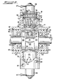
- the engine comprises an engine housing 11 having an enlarged central portion 12 that forms a power shaft chamber 13, and two oppositely extending cylinder portions 14 and 15.
- the two cylinder portions have cylinder heads 17 and 18 secured within them, the inner ends 19 and 20 having reduced diameter sections so that pistons 22 and 23 may be received between the portions 19 and 20 and the inner surfaces of the cylinder portions 14 and 15 of the housing.
- a steam intake passage or port 24 is formed in each cylinder head 17 and 18, and steam injection valves 26 are formed on the two cylinder heads 17 and 18.
- steam injection valves 26 are formed on the two cylinder heads 17 and 18.
- exhaust ports 28 are formed in the housing 11.
- the expansion chambers 27 are placed in communication with the exhaust ports 28, thereby allowing the steam to be exhausted from the two expansion chambers.
- the engine housing further includes an enlarged central portion 12 which forms the enclosure 13, and a power shaft 31 is rotatably mounted and extends through the chamber 13.
- a roller assembly is secured to the power shaft 31, the roller assembly being given the numeral 32, and the roller assembly 32 connects the reciprocating pistons 22 and 23 with the power output shaft 31.
- the roller assembly 32 includes two spaced links 33 and 34 which are rigidly secured to the power output shaft 31, and rollers 36 are rotatably mounted on the ends of the two links 33 and 34. As the shaft 31 rotates and the pistons reciprocate in and out within the cylinders, the rollers 36 roll across the crowns of the two pistons and preferably are in constant contact with the pistons.
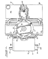
- the housing of the engine further has formed therein an air intake port 41 and an air outlet port 42, and one way or check valves 43 and 44 are mounted in the ports 41 and 42 respectively.
- the valve 43 allows flow of air into the chamber 13 whereas the valve 44 allows air to flow out of the chamber.
- Air flowing out of the chamber through the outlet port 44 is carried by an air line 46 to a boiler or steam generator 47 to be described in greater detail hereinafter in connection with Figures 8 and 9.
- Fuel is also fed into the boiler 47 by a fuel line 48.
- a water intake line 49 carries water to the boiler 47 and a steam outlet line 51 carries the hot steam from the boiler 47 to the engine.
- the water in the line 49 is received from a pump 52 that is connected to the water outlet of a condenser 53.
- the condenser 53 also receives the steam being exhausted through the exhaust ports 28 of the engine, and the condenser 53, of course, serves to cool the steam.
- the heat from the steam is transferred to air which enters the condenser 53 through an air intake line 54, and an air outlet line 56 conducts the air from the condenser 53 to the air intake port 43 of the engine.
- the steam pressure forces the two pistons 22 and 23 radially inwardly, or toward each other, thereby exerting a radially inward force on the two rollers 36.
- the roller assembly 32 and the power output shaft 31 are rotating in the clockwise direction as seen in Figures 1 through 4, the radially inward movement caused by the expanding steam within the expansion chambers 27 will exert a turning force on the roller assembly and the shaft 31, the amount of this torque, of course, being related to the pressure of the steam in the chambers 27.
- the rotation of the shaft 31 may be started by a starting motor (not shown).
- the volume of the chamber 13 is reduced, and the chamber volume is increased as the two pistons move from the TDC positions to the BDC positions.
- This change in volume is utilized to pump air from the condenser 53 to the boiler 47 as previously mentioned.
- the efficiency of the engine system is increased by moving the air through the condenser 53 and thereby preheating it prior to feeding the air into the boiler 47 for combustion purposes, and the movement of the reciprocating pistons of the engine is utilized to move the air.
- the pump 52 of course, circulates the steam and liquid through the boiler 47, the condenser 53 and the engine during the engine operation.
- the power output shaft 31 is rotatably supported by ball bearings 61 which, in turn, are supported by end bells 62 on the engine housing 11.
- Cylindrical openings 63 are formed in the central portion 12 of the housing 11 and the cylindrical end bells 62 are snugly received within the openings 63.
- 0-rings 64 are provided between the engaging surfaces of the housing 11 and the end bells in order to seal the connections.
- circular snap rings 66 are mounted in grooves 67 formed in the inner surfaces of the openings 63, the snap rings 66 engaging the outer surfaces of the two end bells 62.
- end bells 62 may readily be removed merely by removing the snap rings 66 and then sliding the end bells out of the housing.
- Seals 68 are also provided between the shaft 31 and the inner surface of the end bells 62 in order to seal the connections between the shaft and the end bells.
- the two rollers 36 of the roller assembly 32 are mounted on the links 33 and 34 by pins 68 that extend parallel to the power output shaft 31 and are secured to the outer end portions of the two links 33 and 34.
- Roller bearings 69 are provided to mount the rollers 36 for free rotation on the pins 68.
- each piston 22 and 23 includes a straight cylindrical skirt part 72 and the previously mentioned convex dome or crown 71. At the outer end of the skirt 72 of each piston is formed a plurality of axially extending slots 73 which form fingers 74 therebetween. When the pistons are moved to the TDC positions shown in Figure 3, the slots 73 extend inwardly from the cylinder heads 17 and 18 as previously described, thereby enabling steam within the expansion chambers 27 to flow out through the slots 73 and through the steam exhaust ports 28.
- the cylindrical portions 14 and 15 of the engine housing 11 also have cylindrical openings 76 formed therein, the exhaust ports 28 and the steam intake ports 24 being formed in the wall.
- the cylinder heads 17 and 18 are mounted within the cylindrical openings 76 and are retained therein by retainer snap rings 77 that fit in grooves 78 formed in the inner surfaces of the cylindrical portions 14 and 15. As shown in Figure 5, the retainer snap rings 77 engage the outer surfaces of the heads 17 and 18 and normally prevent them from moving out of the opening.
- the head 18 may, however, be disassembled simply by first removing the retainer snap rings 77.
- Each of the cylinder heads 17 and 18 has an annular groove 81 formed therein adjacent its radially outer edge, and a plurality of radially extending passages 82 connect the groove 81 with a central passage 83 formed through the piston.
- a valve seat 84 is formed which mates with the valve stem 26 of, in the present specific example, a solenoid operated steam valve.
- the solenoids are indicated by the reference numeral 86 and are mounted on the radially outer ends of the cylinder heads.
- Conductors 87 extend from the solenoid coils (not shown) of the solenoids 86 to a control circuit to be discussed hereinafter.
- each solenoid 86 When each solenoid 86 is energized by passing current through it, it moves the valve stem or plunger 26 radially outwardly and thereby away from the valve seat 84 in order to allow steam to flow from the central passage 83 to the expansion chamber 27.
- the construction for the other cylinder head 17 is, of course, the same.
- 0-rings 85 are provided between the cylinder head and the engine housing 11 on opposite sides of the groove 81 in order to seal the groove.
- piston rings 87 are provided on each cylinder head and in engagement with the inner periphery of the associated piston in order to seal the expansion chamber 27 when the piston is moved radially outwardly.
- a piston ring 88 is also provided in the engine housing 11 and in engagement with the outer surface of each piston, the piston rings 87 and 88 thereby supporting and guiding the reciprocating movement of the piston.
- the pistons are, however, able to rotate on their axis during operation of the engine, and this is advantageous because it continuously presents new bearing or wear surfaces to the rollers 36.
- the solenoid coil is connected by the wires or conductors 87 to an electric control circuit that also includes a wiper 91, shown in Figure 10.
- the wiper 91 is connected by a conductor 92 to a voltage source such as a battery 93 and from the battery to the solenoid coils.
- a pair of arcuate contacts 94 and 95 are mounted on the outer periphery of a wheel 97 that is fastened to a rotating shaft 98 which is coupled to rotate in synchronism with the power output shaft. Between the two arcuate contacts 94 and 95 are insulators 99. Thus, as the shaft 98 and the wheel 97 are rotating, the wiper 91 engages the two contacts 94 and 95.
- the circuit is completed through the battery 93 and the solenoid coil each time the wiper 91 engages one of the contacts 94 and 95, and this may accomplished, for example, by grounding the contacts 94 and 95 and one side of the solenoid coil, the other side of the solenoid coil being connected to the battery 93.
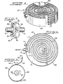
- the steam boiler is better illustrated in Figures 6, 8 and 9.
- the boiler includes a drum-like housing including flat bottom and top walls 101 and 102 and a cylindrical side wall 103.
- An opening 104 is formed in the bottom wall 101 that receives the fresh air from the outlet 42 of the engine housing 11, and adjacent the air intake opening 104 is a fuel intake opening 106 ( Figure 9).
- the igniter such as a spark plug 107 ( Figure 6) is mounted at approximately the center of the boiler by, for example, mounting it on the top wall 102, as shown in Figure 6.
- the center area of the housing forms a combustion chamber when air and fuel are admitted through the openings 104 and 106 and the igniter 107 is operated.
- a steam outlet manifold 108 that extends between the bottom and top walls 101 and 102 and is secured thereto. Spiralling outwardly from the manifold 108 is a wall 109 that has its inner end connected to the steam outlet manifold 108 and its outer end 110 connected to a water inlet manifold 112. Suitable couplings 113 are connected to the manifolds 108 and 112 for connecting the steam and water to the adjoining parts of the system.
- An exhaust outlet tube 114 is connected in the cylindrical outer wall 103 of the boiler and is in communication with the interior boiler area adjacent the manifold 112.
- a plurality of tubes 117 which are connected to both the manifolds 108 and 112.
- water flows into the coupling 113 and the manifold 112, and into the outer ends of the tubes 117.
- the water then flows in a spiral path in the direction of the center of the boiler until it reaches the outlet manifold 108 and then is led out of the boiler.
- the heat and exhaust generated in the combustion chamber adjacent the fuel and air openings 104 and 106 flows in a spiral path from the center of the boiler in a radially outward direction to the exhaust outlet 114.
- the center part or combustion chamber area of the boiler is, of course, the hottest and consequently'the water flows from an area of relatively cool temperature, adjacent the manifold 112, to an increasingly hot area adjacent the outlet 108.
- the spirally flowing water is quickly flash-heated to steam by the time it arrives at the steam-outlet manifold 108.
- the condenser 53 includes a housing 121 having a fresh air intake opening 122 formed therein adjacent its outer side wall. The air flows into the intake 122 and follows a spiral path as it moves inwardly to the center of the housing 121 and then enters the air intake opening 41 of the engine housing 11.
- the housing 121 includes a spiral wall similar to the wall 110 of the boiler 47 which causes the spiral movement of the flowing air.
- the steam exhausted from the cylinders flows out of the exhaust ports 28 and through exhaust tubes 123 to a steam intake manifold 124 at approximately the center of the housing 121.
- the steam flows through a plurality of heat-exchanger spiral tubes similar to the tubes 117.
- the tubes are, of course, also in contact with the air flowing from the intake 122 to the outlet 41, and the steam is cooled by heat-exchanger action as it flows through the condenser from the manifold 124 to the outlet manifold 126.
- the manifold 126 is connected by a tube 127 to the intake of the pump 52 ( Figure 1). It should be apparent that the condenser 53 is also efficient in operation because the steam entering the condenser at the manifold 124 flows in the direction of an increasingly cooler air temperature area, thereby improving or increasing the efficiency of operation of the condenser.
- the curvature of the crown or dome 71 of each piston and the mating curvature of the adjacent roller serves to increase the bearing area between the two parts, thereby reducing the stresses on the parts.
- the two pistons are free to rotate on their axes during operation of this system so that the pistons, by rotating, present changing bearing surfaces to the rollers 36, which, of course, also reduces wear on the pistons.
- a back pressure may be maintained in the exhaust steam lines connected to the exhaust ports 28 in order to hold the pistons against the rollers 36 and thereby to prevent the pistons from slapping against the rollers.
- the back pressure may be approximately 15 to 20 p.s.i. or higher, and this may be accomplished by forming a restriction in the steam exhaust line if the back pressure does not naturally appear from the sizing of the tubes. The back pressure also enhances the condenser operation.
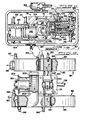
- Figures 11 and 12 show another embodiment of the invention including an engine housing 131 including a central portion 132 and two cylinder portions 133 and 134.
- the cylinders of the invention are preferably formed in pairs as shown in Figs. 11 and 12 and one or more pairs of cylinders may be provided.
- the central portion 132 is generally similar to the central portion of the engine shown in Figs. 1-5 and includes a central opening 133 that contains a roller assembly 134.
- the roller assembly 134 is mounted on a power output shaft 136 and includes parallel links 137 and rollers 138 on opposite sides of the shaft 136, similar to the arrangement shown in Figs. 1-5.
- the power output shaft 136 is mounted on bearings for rotation about the axis of the output shaft 136, and the axis of the shaft is substantially perpendicular of the axes of the cylinder portions 133 and 134.
- the housing portion 132 also includes an air inlet opening 139 and an air outlet opening 141 for the passage of air from the condenser to the boiler.
- Check valves (not shown) are provided in the openings 139 and 141, similar to the valves 43 and 44, for allowing air to flow only in the direction from the condenser to the boiler. As previously described, during operation of the engine the reciprocating motions of the pistons cause the air to be pumped through the housing portion 132.
- Each of the cylinder portions includes a generally tubular outer cylinder part 142 and a cylinder head 143.
- the part 142 and the head 143 form an annular passage 144 between them, and a piston 146 is mounted for reciprocating motion in the passage 144.
- the piston 146 includes a piston head or crown 147 and a cylindrical skirt 148, and a skirt 148 extends into the annular passage 144.
- the axes of the pistons and the cylinders are offset from each other on opposite sides of the axis of the shaft 136.
- the shaft 136 and the roller assembly rotate in the counterclockwise direction, as seen in Fig. 11, and the offset of the piston axes from the shaft 136 axis is advantageous in that it provides greater bearing surface and therefore more effective contact between the parts during the expansion or power strokes of the pistons.
- the cylinder head 143 and the interior of the piston 147 form an expansion chamber 151 between them, similar to the chamber 27 shown in Figs 1-5.
- the piston of each cylinder is forced toward the top dead center position, which, as defined herein, is the point where the piston is nearest to the shaft 136.
- the heated vapor which is preferably steam, is received from a boiler by way of a steam line 153 and a control valve 154.
- a steam line 153 When the valve 154 is opened, steam flows through the line 153 and into a steam chamber 156 formed within the cylinder head 143.
- a steam valve 157 mounted on the cylinder head 143 controls the flow of steam from the steam chamber 156 to the expansion chamber 151.
- a valve opening 158 is formed at the center of the cylinder head 143 and the head 159 of the valve 157 is operable to open or close the opening 158.
- the stem 161 of the valve 157 is movable in a guide passage 162 formed in the head 143, and the outer end of the stem 161 is subjected to the pressure of a hydraulic liquid in the passage 162.
- a hydraulic pump 163 is connected by pressure lines 164 to the passage 162 of each cylinder.
- the hydraulic pressure in the passages 162 is controlled by a solenoid operated control valve 166 which is also connected to the passages 162 and the lines 164.
- the control valve 166 is also connected by a return line 167 to a hydraulic reservoir 168 which returns the hydraulic liquid from the valve 166 to the intake of the pump 163.
- the pump 163 is operating substantially continuously and produces a relatively high pressure on the hydraulic liquid in the lines 164 and the passages 162 when the valve 166 is essentially closed, the pressure will be substantially reduced when the valve 166 opens and enables the hydraulic liquid in the lines 164 to be bypassed to the line 167 and to the reservoir 168.
- the valves 157 are moved to close the openings 158 and thereby prevent the flow of steam from the steam chamber 156 to the expansion chambers 151.
- the steam pressure in a specific example of the invention, may be approximately 2,000 p.s..i. and the hydraulic liquid pressure in the passages 162 when the valve 166 is closed may be approximately 3,000 p.s.i.
- the hydraulic liquid pressure in the passages 162 is sufficient to force the steam valves 157 to the closed position.
- the hydraulic valve 166 is opened, the pressure in the passages 162 is released and the pressure in the chamber 151 is sufficient to open the valve 157.
- the hydraulic valve 166 is connected to a mechanism such as that shown in Fig. 10 for cyclically opening and closing the valve 166 in synchronism with the rotation of the power output shaft 136.
- means is also provided for moving the pistons 146 to their retracted or bottom dead center positions.
- This means comprises a high pressure vapor or steam line 171 which is connected through a valve 172 to a retraction chamber 173 formed between the skirt 148 of the piston and the outer cylinder part 142.
- the piston skirt 148 is recessed in the area indicated by the numeral 174 to form the retraction chamber 173.
- high pressure steam enters the retraction chamber 173, it exerts pressure against the shoulder forming the reduced diameter part of the skirt and forces the pistons outwardly or to their bottom dead center positions.
- the retraction valves 172 are operated in synchronism with the control valves 154 so that the steam pressure in the chambers 156 is present only when the valves 172 are closed and pressure in the retraction chambers 173 is absent. The converse is, of course, also true.
- the arrangement of the retraction chamber is particularly advantageous when the engine is being started so that the pistons may be held at the bottom dead center positions and out of engagement with the roller assembly during the starting of the engine. Such operation enables a freewheeling action of the roller assembly which makes it easier to start the engine.
- the retraction valve may also be utilized when the engine is to be coasted during a period of normal operation, to prevent the roller assembly from slapping against the piston crowns.
- the cylinders also include steam return passages which lead to a return line 176 for exhausting the steam from the cylinders as previously described.
- the exhaust lines 176 lead to the condenser of the engine.
- Fig. 12 shows the arrangement of the boiler 181 and the condenser 182 in more detail.
- the boiler 181 is similar to the boiler 47 except that the internal spiral wall 110 has been deleted.
- the boiler 181 includes a plurality of tubes, which could, of course, be a single flattened tube 182, which extends essentially the full distance between the side plates 183 and 184 of the boiler.
- the tubes 182 form both a passage means for the steam-liquid and a wall for routing the exhaust gases of the burner from the central combustion chamber to an exhaust outlet port 186.
- the boiler 181 also includes a liquid intake line 187, a steam or heated vapor line 188, a fuel inlet line 189 and an igniter 190. In other respects, the boiler 181 is similar to the boiler 47.
- the condenser 182 is constructed quite similarly to the boiler 181 and includes a housing 192 and tubes 193 which carry the water-vapor and also form a spiral wall for the air flowing through the condenser 182.
- the exhaust steam from the engine enters the condenser 182 through an inlet 194 and leaves the condenser through a condensate outlet 196.
- the condenser 182 preferably also includes a burner for preheating the air which enters the condenser 182 when the engine is being started in cold weather.
- the heater or burner includes a fuel intake line 197 and an igniter 198 which are located adjacent the outer periphery of the housing 192 adjacent the air intake. The air may thus be preheated during cold weather to prevent cold air from freezing the liquid in the tubes 193 before the boiler 181 is able to raise the temperature of the liquid. Once the engine has warmed to normal operating temperatures, the condenser burner may be turned off.
- the blower 200 includes a cowling 202 through which the intake air flows to the blower 200, and a duct 203 which leads the intake air from the blower 200 to the air intake of the condenser 182.
- the starter-generator is used to rotate the power output shaft 136 in order to pump intake air through the housing 131 as the engine is being started, and the starter-generator 201 may also be used to generate electricity and recharge an engine battery during normal engine operation.
- the engine may utilize a variety of other fuels such as gas or a solution including ground up coal.
- a system may include a plurality of engines of the character described herein, connected to the same power output shaft 31. By angularly displacing the cylinders of the engine, a more continuous output torque would be obtained.
Landscapes
- Engineering & Computer Science (AREA)
- Mechanical Engineering (AREA)
- General Engineering & Computer Science (AREA)
- Physics & Mathematics (AREA)
- Thermal Sciences (AREA)
- Chemical & Material Sciences (AREA)
- Combustion & Propulsion (AREA)
- Engine Equipment That Uses Special Cycles (AREA)
- Combustion Methods Of Internal-Combustion Engines (AREA)
- Luminescent Compositions (AREA)
- Cylinder Crankcases Of Internal Combustion Engines (AREA)
- Valve Device For Special Equipments (AREA)
Applications Claiming Priority (2)
| Application Number | Priority Date | Filing Date | Title |
|---|---|---|---|
| US06/554,603 US4561256A (en) | 1983-01-05 | 1983-11-25 | External combustion engine |
| US554603 | 1983-11-25 |
Publications (2)
| Publication Number | Publication Date |
|---|---|
| EP0143672A2 true EP0143672A2 (de) | 1985-06-05 |
| EP0143672A3 EP0143672A3 (de) | 1987-12-16 |
Family
ID=24213980
Family Applications (1)
| Application Number | Title | Priority Date | Filing Date |
|---|---|---|---|
| EP84401467A Withdrawn EP0143672A3 (de) | 1983-11-25 | 1984-07-10 | Brennkraftmaschine mit äusserer Verbrennung |
Country Status (3)
| Country | Link |
|---|---|
| US (1) | US4561256A (de) |
| EP (1) | EP0143672A3 (de) |
| JP (1) | JPS60119301A (de) |
Cited By (1)
| Publication number | Priority date | Publication date | Assignee | Title |
|---|---|---|---|---|
| CN118980268A (zh) * | 2024-08-02 | 2024-11-19 | 江西金德铅业股份有限公司 | 一种用于脱硫系统的余热利用装置 |
Families Citing this family (10)
| Publication number | Priority date | Publication date | Assignee | Title |
|---|---|---|---|---|
| US7080512B2 (en) * | 2004-09-14 | 2006-07-25 | Cyclone Technologies Lllp | Heat regenerative engine |
| CN100462526C (zh) * | 2004-09-14 | 2009-02-18 | 赛克龙技术有限责任有限合伙公司 | 热量回授式发动机 |
| US9316130B1 (en) | 2007-03-07 | 2016-04-19 | Thermal Power Recovery Llc | High efficiency steam engine, steam expander and improved valves therefor |
| US8661817B2 (en) * | 2007-03-07 | 2014-03-04 | Thermal Power Recovery Llc | High efficiency dual cycle internal combustion steam engine and method |
| US8448440B2 (en) * | 2007-03-07 | 2013-05-28 | Thermal Power Recovery Llc | Method and apparatus for achieving higher thermal efficiency in a steam engine or steam expander |
| US8061140B2 (en) * | 2007-03-07 | 2011-11-22 | Thermal Power Recovery Llc | High efficiency multicycle internal combustion engine with waste heat recovery |
| RU2346174C1 (ru) * | 2007-07-17 | 2009-02-10 | Сергей Павлович Морозов | Тепловая электростанция, работающая на жидком, твердом топливе и выхлопных газах двигателя одновременно |
| WO2011128773A1 (en) * | 2010-04-13 | 2011-10-20 | Hunt Robert D | Exhaust actuated free-piston kinetic engine |
| CN103925109B (zh) * | 2014-04-30 | 2015-07-08 | 郭远军 | 一种水平对置式热能动力设备及其做功方法 |
| CN103912323B (zh) * | 2014-04-30 | 2015-07-08 | 郭远军 | 一种v型热能动力设备及其做功方法 |
Family Cites Families (23)
| Publication number | Priority date | Publication date | Assignee | Title |
|---|---|---|---|---|
| FR397812A (fr) * | 1907-12-23 | 1909-05-18 | Heinrich Langer | Appareil clos à serpentin et à contre-courant pouvant servir de réfrigérant et de réchauffeur |
| US1488528A (en) * | 1920-08-07 | 1924-04-01 | Cardini Luigi | Pneumatic rotary motor |
| GB232074A (en) * | 1924-06-17 | 1925-04-16 | James Mccobb Seldon | Improvements relating to steam generators |
| US2578059A (en) * | 1945-05-29 | 1951-12-11 | Graham Mfg Co Inc | Heat interchanger |
| US2852184A (en) * | 1957-05-27 | 1958-09-16 | Gen Motors Corp | Air compressor |
| US3006612A (en) * | 1958-03-17 | 1961-10-31 | Borg Warner | Heat exchangers |
| US3282257A (en) * | 1963-06-05 | 1966-11-01 | Vapor Corp | Fluid heating apparatus |
| US3251183A (en) * | 1964-05-13 | 1966-05-17 | John B Whitlow | Internally generated steam engine |
| US3274982A (en) * | 1964-09-23 | 1966-09-27 | To Yota Motors Company | Two-cycle two-cylinder internal combustion engine |
| US3285503A (en) * | 1965-03-18 | 1966-11-15 | Bancroft Charles | Fluid displacement device |
| CH456664A (de) * | 1965-12-20 | 1968-07-31 | Harzer Achsenwerke Kg Schweman | Spiralrohr-Wärmetauscher |
| DE2042632A1 (de) * | 1970-08-27 | 1972-03-02 | Motorenfabnk Hatz GmbH, 8399 Ruhs torf | Kolbenmaschine |
| GB1313154A (en) * | 1970-10-26 | 1973-04-11 | Dewandre Co Ltd C | Spiral flow heat exchanger |
| US3672260A (en) * | 1970-12-14 | 1972-06-27 | Jean Gachot | Compressed-air actuator |
| FR2129027A5 (de) * | 1971-03-10 | 1972-10-27 | Lang Claude | |
| FR2155770A1 (en) * | 1971-10-04 | 1973-05-25 | Ind Chauffage | Spiral tube heat exchanger - with tubes contacting shell to define shell-side flow |
| US3841273A (en) * | 1973-09-27 | 1974-10-15 | Sioux Steam Cleaner Corp | Multi-pass heating apparatus with expandable air cooled jacket |
| US3990238A (en) * | 1975-09-26 | 1976-11-09 | Bailey Joseph H | Steam engine |
| US4055951A (en) * | 1976-08-16 | 1977-11-01 | D-Cycle Associates | Condensing vapor heat engine with two-phase compression and constant volume superheating |
| FI61956C (fi) * | 1978-09-05 | 1982-10-11 | Outokumpu Oy | Roerspiralpaket foer en vaermevaexlare samt foerfarande foer framstaellning av detsamma |
| AT369533B (de) * | 1979-04-26 | 1983-01-10 | Chaffoteaux Et Maury | Warmwasserbereiter |
| DE8117144U1 (de) * | 1981-03-31 | 1981-11-26 | Feraton Anstalt, 9494 Schaan | Waermetauscher |
| JPS5812944A (ja) * | 1981-07-17 | 1983-01-25 | Bunka Buro Sangyo Kk | 一缶二水路式給湯兼用風呂釜 |
-
1983
- 1983-11-25 US US06/554,603 patent/US4561256A/en not_active Expired - Fee Related
-
1984
- 1984-07-10 EP EP84401467A patent/EP0143672A3/de not_active Withdrawn
- 1984-07-27 JP JP59158546A patent/JPS60119301A/ja active Pending
Cited By (1)
| Publication number | Priority date | Publication date | Assignee | Title |
|---|---|---|---|---|
| CN118980268A (zh) * | 2024-08-02 | 2024-11-19 | 江西金德铅业股份有限公司 | 一种用于脱硫系统的余热利用装置 |
Also Published As
| Publication number | Publication date |
|---|---|
| EP0143672A3 (de) | 1987-12-16 |
| JPS60119301A (ja) | 1985-06-26 |
| US4561256A (en) | 1985-12-31 |
Similar Documents
| Publication | Publication Date | Title |
|---|---|---|
| US4611655A (en) | Heat exchanger | |
| KR100930435B1 (ko) | 열 재생 엔진 | |
| US4561256A (en) | External combustion engine | |
| US3830208A (en) | Vee engine | |
| US4212163A (en) | Heat engine | |
| US5074253A (en) | Volumetric displacement machine with double-action oscillating pistons | |
| EA005304B1 (ru) | Моторгенератор | |
| EP0087242B1 (de) | Kraftanlage | |
| JP2557616B2 (ja) | 燃焼機関 | |
| US5758610A (en) | Air cooled self-supercharging four stroke internal combustion engine | |
| CA2033462C (en) | Engine system using refrigerant fluid | |
| RU2394163C2 (ru) | Системы радиально-импульсного двигателя, насоса и компрессора и способы их работы | |
| US6314925B1 (en) | Two-stroke internal combustion engine with recuperator in cylinder head | |
| CN111379644A (zh) | 一种新型发动机用的活塞组件和新型发动机 | |
| US3851630A (en) | Rotary piston engine | |
| US6148775A (en) | Orbital internal combustion engine | |
| US3934418A (en) | Turbine engine | |
| US5507142A (en) | Hybrid steam engine | |
| EP1147292B1 (de) | Hebelsystem für motor oder pumpe | |
| CN210686064U (zh) | 一种储压式发动机 | |
| RU2357091C2 (ru) | Двигатель с регенерацией тепла | |
| WO1984004779A1 (en) | Internal combustion engine | |
| WO2003046347A1 (en) | Two-stroke recuperative engine | |
| US4086771A (en) | Combined internal combustion and heat engine | |
| US7134270B2 (en) | External combustion engine |
Legal Events
| Date | Code | Title | Description |
|---|---|---|---|
| PUAI | Public reference made under article 153(3) epc to a published international application that has entered the european phase |
Free format text: ORIGINAL CODE: 0009012 |
|
| AK | Designated contracting states |
Designated state(s): AT BE CH DE FR GB IT LI LU NL SE |
|
| 17P | Request for examination filed |
Effective date: 19870611 |
|
| PUAL | Search report despatched |
Free format text: ORIGINAL CODE: 0009013 |
|
| AK | Designated contracting states |
Kind code of ref document: A3 Designated state(s): AT BE CH DE FR GB IT LI LU NL SE |
|
| STAA | Information on the status of an ep patent application or granted ep patent |
Free format text: STATUS: THE APPLICATION IS DEEMED TO BE WITHDRAWN |
|
| 18D | Application deemed to be withdrawn |
Effective date: 19880617 |
|
| RIN1 | Information on inventor provided before grant (corrected) |
Inventor name: MOLIGNONI, ALBERT J. |