EP0143660A2 - Resistors, methods of forming said resistors, and articles comprising said resistors - Google Patents
Resistors, methods of forming said resistors, and articles comprising said resistors Download PDFInfo
- Publication number
- EP0143660A2 EP0143660A2 EP84308273A EP84308273A EP0143660A2 EP 0143660 A2 EP0143660 A2 EP 0143660A2 EP 84308273 A EP84308273 A EP 84308273A EP 84308273 A EP84308273 A EP 84308273A EP 0143660 A2 EP0143660 A2 EP 0143660A2
- Authority
- EP
- European Patent Office
- Prior art keywords
- ink
- composition
- weight
- carbon
- length
- Prior art date
- Legal status (The legal status is an assumption and is not a legal conclusion. Google has not performed a legal analysis and makes no representation as to the accuracy of the status listed.)
- Withdrawn
Links
Classifications
-
- H—ELECTRICITY
- H01—ELECTRIC ELEMENTS
- H01C—RESISTORS
- H01C17/00—Apparatus or processes specially adapted for manufacturing resistors
- H01C17/06—Apparatus or processes specially adapted for manufacturing resistors adapted for coating resistive material on a base
- H01C17/065—Apparatus or processes specially adapted for manufacturing resistors adapted for coating resistive material on a base by thick film techniques, e.g. serigraphy
- H01C17/06506—Precursor compositions therefor, e.g. pastes, inks, glass frits
- H01C17/06513—Precursor compositions therefor, e.g. pastes, inks, glass frits characterised by the resistive component
- H01C17/0652—Precursor compositions therefor, e.g. pastes, inks, glass frits characterised by the resistive component containing carbon or carbides
-
- H—ELECTRICITY
- H01—ELECTRIC ELEMENTS
- H01C—RESISTORS
- H01C17/00—Apparatus or processes specially adapted for manufacturing resistors
- H01C17/06—Apparatus or processes specially adapted for manufacturing resistors adapted for coating resistive material on a base
-
- H—ELECTRICITY
- H01—ELECTRIC ELEMENTS
- H01C—RESISTORS
- H01C17/00—Apparatus or processes specially adapted for manufacturing resistors
- H01C17/06—Apparatus or processes specially adapted for manufacturing resistors adapted for coating resistive material on a base
- H01C17/065—Apparatus or processes specially adapted for manufacturing resistors adapted for coating resistive material on a base by thick film techniques, e.g. serigraphy
- H01C17/06506—Precursor compositions therefor, e.g. pastes, inks, glass frits
- H01C17/06573—Precursor compositions therefor, e.g. pastes, inks, glass frits characterised by the permanent binder
- H01C17/06586—Precursor compositions therefor, e.g. pastes, inks, glass frits characterised by the permanent binder composed of organic material
Definitions
- the invention concerns resistors. More particularly the invention concerns resistors, e.g. polymer thick film resistors, methods of making said resistors, and articles comprising said resistors.
- resistors e.g. polymer thick film resistors
- Polymer thick film systems are based on organic mediums or vehicles. Typically, the thick film conductors are metal filled (usually silver) and the thick film resistors contain carbon. Polymer thick film components find wide applications such as in windshield wiper controls, calculator keyboards, automotive defrosters, flash bulb arrays, recording consoles, and have many advantages over prior resistor systems. For example, polymer thick film components are light in weight compared to the components they replace and it has been estimated that 136.08 kg (300 pounds) could be eliminated from a typical jet fighter plane by the use of polymer thick film components.
- polymer thick film resistors and conductors are conventionally formulated in an ink which is then screen printed on a thermally stable substrate to form a film thereon. This film is then cured at temperatures ranging from 125 to 600°C.
- Typical inks for known polymer thick film resistors have been conventionally formulated from mixtures of carbon black and epoxy or from mixtures of carbon black and polyimide. These resistors do not, however, exhibit good electrical characteristics, such as immunity to thermal influence. These resistors do not achieve as small a percentage change of sheet resistivity during cure, as low a temperature coefficient of resistance or as small a percentage change in resistance during solder dip as desired for the thick film circuit applications described above.
- a resistor composition comprising carbon particles embedded in a matrix comprising polymer containing units derived from short chain-length phenolic resin, long chain-length phenolic resin and epoxy.
- the matrix also comprises filler.
- the composition can be formed by mixing solvent, short chain-length phenolic resin, long chain-length phenolic resin and, if present, filler with carbon particles to form a solution.
- the solution which is in the form of a liquid mixture, is allowed to cool and then mixed with epoxy to form an ink.
- the ink is then applied to a substrate and cured, during which solvent evaporation occurs, leaving a resistor film on the substrate.
- the resistor composition of the present invention may be formulated as either a low, medium or high resistance resistor composition.
- the low resistance composition provides resistance values from 1 ohm to 850 ohms.
- the medium resistance composition provides resistance values from 500 ohms to 2.0 K ohms.
- the high resistance composition provides resistance values from 500 K ohms to 2.0 M ohms.
- the short chain-length phenolic resin may be a phenol-formaldehyde resin such as that sold by Clark Chemical Corporation under the designation CR 3558.
- Another suitable short chain-length phenolic resin is that sold by Union Carbide Corporation under the designation BKR 2620.
- the resin is in liquid form and is made up of approximately 50% phenolic and 50% solvent (such as methanol).
- the short chain-length phenolic resin preferably makes up 50 to 60% by weight before cure of each of the resistor compositions.
- the long chain-length phenolic resin may be a phenol-formaldehyde resin such as that sold by the Union Carbide Corporation under the designation BLS 2700.
- Another suitable long chain-length phenolic resin is that sold by Reichhold Chemical, Inc. under the designation VARCUM 29112.
- This phenolic resin is in liquid form and is made up of approximately 60% phenolic and 40% solvent (such as ethanol). The solvent will evaporate from the ink during curing.
- the long chain-length phenolic resin preferably makes up 8 to 15% by weight before cure of each of the resistor compositions.
- the epoxy can be any suitable epoxy such as the moderate chain-length epoxy sold by Shell under the designation 828, the epoxy sold by London Chemical Co. under the designation Lonco PC 549 solder resist or the epoxy sold by Mac Dermid Inc. under the designation 9440 solder resist.
- the epoxy preferably makes up 10 to 20% by weight before cure of each of the resistor compositions.
- the filler e.g. used in the high medium resistance compositions, may be a mixture of zinc oxide and boron nitride.
- the zinc oxide preferably makes up 1 to 5% by weight before cure of the high and medium resistance compositions and the boron nitride preferably makes up 3.5 to 10% by weight before cure of these compositions.
- Filler is not required in the low resistance composition. However, for very low resistance values, such as 1 ohm to 150 ohms, metallic silver flake particles may be added to the low resistance composition as filler.
- the carbon used includes high structure carbon such as that sold by the Cabot Corp. under the designation Vulcan XCR-72.
- High structure carbon has a chain-like structure and gives a low sheet resistivity.
- High structure carbon preferably makes up 1 to 4%, more preferably 1 to 3%, by weight before cure of each of the resistor compositions.
- the high resistance composition includes high structure carbon and low structure carbon such as that sold by Cabot Corp. under the designation MOGUL L.
- Low structure carbon is composed of short groups or individual particles and gives a high sheet resistivity. This low structure carbon preferably makes up 10 to 15% by weight before cure of the high resistance composition.
- the medium resistance composition may include high structure carbon and carbon black, e.g.
- acetylene black such as that available from Gulf Oil Chemicals.
- the carbon black e.g. acetylene black
- the low resistance composition may include high structure carbon and commercial grade graphite powder which is crystalline in structure and provides a low sheet resistivity.
- the graphite preferably makes up 10 to 20% by weight before cure of the low resistance composition.
- Each resistance composition is formed by combining the short chain-length phenolic resin, the long chain-length phenolic resin and, if present, filler with a suitable solvent, typically butyl carbitol acetate or butyl carbitol.
- a suitable solvent typically butyl carbitol acetate or butyl carbitol.
- the solvent preferably makes up 2 to 10% by weight before cure of each resistance composition.
- the phenolic resins, solvent and, if present, filler are mixed, e.g. by a standard Hobart mixer set at a medium speed.
- the carbons particular to the resistance composition being formed are then added and mixing continues so that the carbon particles are dispersed.
- the graphite is milled using a ball mill, e.g. to obtain a fineness of grind of less than 7 micrometres.
- the high structure carbon is added to the graphite and milled again so as to create a mixture of the two carbons.
- the resulting solution is then permitted to cool before being mixed with the epoxy to form an ink.
- the ink is then milled using a paint mill until the desired fineness of grind is achieved. This may require a minimum of four passes through the paint mill. A fineness of grind of seven micrometres or less is desirable.
- the viscosity of the ink may be lowered with the addition of more solvent in 0.5% by weight increments to reach the viscosity desired for the particular application. For the high resistance composition a viscosity of 50 to 90 Pa s [50,000 to 90,000 centipoise (cps)] at 25°C is desired for most applications, with a preferred viscosity being 70 Pa s (70,000 cps).
- the ink may then be applied to any substrate capable of withstanding the curing temperature of the ink.
- Typical substrates include those formed from epoxy and fiberglass.
- the ink may be screen printed onto conventional circuit boards to provide a resistor between one element of a circuit and another.
- the ink may be screen printed using conventional silk screening methods to form lines of the resistor composition as narrow as 0.254 mm (10 mils) in width and with a spacing of as little as 0.254 mm (10 mils) from other lines.
- the ink should be applied at a wet thickness of 20 to 50 micrometres with a preferred range being 36 to 38 micrometres.
- the ink forms a film on the substrate which then must be cured.
- the film may be cured by exposing the substrate to an ambient temperature of 160 to 170°C for approximately three hours. This may be done by placing the substrate in a convection oven, having a nitrogen or oxygen atmosphere. Alternatively, the film may be cured by placing the substrate in an infrared oven and exposing the substrate to temperature of at least 165°C for approximately 12 minutes. This alternative curing procedure may be useful for protecting heat sensitive substrates.
- the solvents (the solvents contained in the phenolic resins and the solvent added to form the ink) are evaporated and polymerization occurs, leaving a hard, solderable resistor film formed from carbon embedded in a matrix comprising filler (if present) and polymer containing units derived from short and long chain-length phenolic resins and epoxy.
- the thickness of the cured film typically is approximately 25 micrometres.
- the resistance of films formed from the high resistance composition may vary from a low of 500 K ohms to a high of 2.0 M ohms by varying the percentages of low and high structure carbon and short and long chain-length phenolic resins. Specifically, for resistance values at the top end of the range the percentage of low structure carbon and phenolic resins should be increased.
- the resistance of films formed from the medium resistance composition and comprising carbon in the form of high structure carbon and acetylene black may vary from a low of 500 ohms to a high of 2.0 K ohms by varying the percentages of the acetylene black and the high structure carbon. Specifically, to lower the resistance of the blend the amount of high structure carbon can be increased while decreasing the amount of acetylene black. For resistance values at the higher range the reverse procedure can be utilized.
- the resistance of films formed from the low resistance composition may vary from a low of 1 ohms to a high of 850 ohms. Resistance values between 1 ohms and 150 ohms are achieved when metallic silver particles are used as filler. Resistance values between 150 ohms and 850 ohms are achieved without the use of filler and by varying the percentages of the carbons and the phenolic resins.
- TCR temperature coefficient of resistance
- TCR of zero With a medium resistance composition a TCR of zero, plus or minus 300 PPM/°C has been achieved over a temperature change of -55 to 125°C. With a low resistance blend a TCR of zero, plus or minus 200 PPM/°C has been achieved over a temperature range of -55 to 125°C.
- %AR percent change in resistance
- a % ⁇ R during solder dip of only 2% has been achieved with each of the resistor compositions of the present invention.
- a %LR during cure of -5 to -15% has been achieved with each of the resistor compositions of the present invention.
- This small change in sheet resistivity during cure is evidence of a high degree of thermal stability.
- a %L 1 R during burn in (a procedure in which the resistor composition is subjected to 85°C for 10 hours) of -5 to -10% has been achieved with each of the resistor compositions of the present invention.
- each of the resistor compositions of the present invention can be achieved by balancing the thermal characteristics of the phenolic and epoxy polymers, carbon and fillers. It is also possible to manipulate these ingredients to achieve a particular thermal characteristic required by a particular user.
- the boron nitride contributes to a negative TCR but improves the solderability of the system and helps to minimize the change in resistance of the composition during solder dip. In situations where a negative TCR is acceptable the percentage of boron nitride may be increased to further minimize the %0 R during solder dip.
- Two or more of the resistor compositions according to the invention may be mixed together, to form resistor compositions having different resistance values.
- the low resistance composition may be directly mixed with either the medium or high resistance compositions and vice versa.
- mixing should be based on logarithmic proportions.
- the ink of a 1 K ohm resistor composition should be mixed with the ink of a 100 K ohms resistor composition in a 50% to 50% ratio.
- the resulting 10 K ohms resistor composition could then be used with the 100 K ohms resistor composition in a 30% to 70% ratio to form a 50 K ohms resistor composition.
- a specific example of a high resistance resistor composition was formed using the ingredients and procedures described above.
- the amounts of the ingredients (by weight and before cure) of the composition were as follows:
- Inks formed from these ingredients in these proportions were cured, and the cured films were found to have a resistance of 1.25M ohms per square per 0.025 mm (1 mil) thick, plus or minus 750 K ohms. Any size square of the cured film having a thickness of 0.025 mm (1 mil) will have a resistance of 1.25M ohms, plus or minus 750 K ohms.
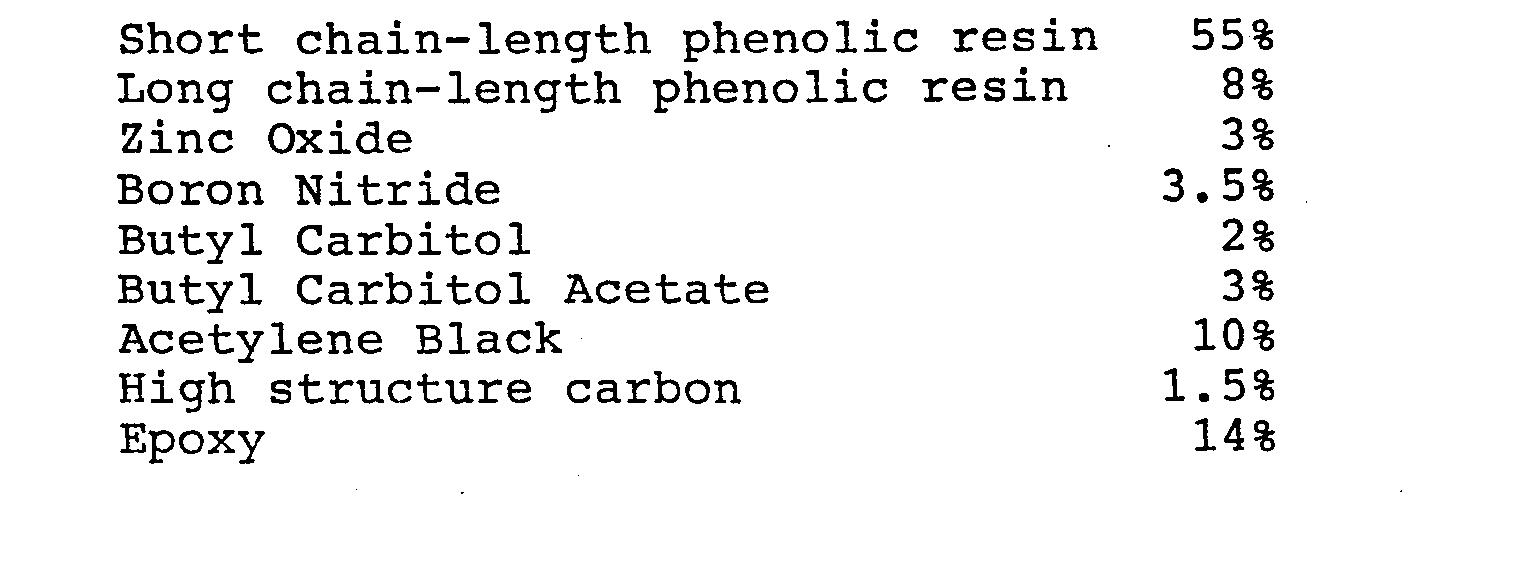
- a specific example of a medium resistance resistor composition was formed using the ingredients and procedures described above.
- the amounts of the ingredients (by weight and before cure) of the compositions were as follows:
- Inks formed from these ingredients in these proportions were cured, and the cured films were found to have a resistance of 1.25 K ohms per square per 0.025 mm (1 mil) thick, plus or minus 750 ohms.
- a specific example of a low resistance resistor composition was formed using the ingredients and procedures described above.
- the amounts of the ingredients (by weight and before cure) of the composition were as follows:
- Inks formed from these ingredients in these proportions were cured, and the cured films were found to have a resistance of approximately 250 ohms per square per 0.025 mm (1 mil) thick.
- a specific example of a low resistance resistor composition utilizing metallic silver particles was formed using the ingredients and procedures described above.
- the amounts of the ingredients were as follows: The silver particles were mixed into the composition at the same time as the phenolic resins.
- Inks formed from these ingredients in these proportions were cured and the cured films were found to have a resistance of approximately 150 ohms per square 0.02 5 mm (1 mil) thick.
- the ink of the high resistance composition (which was specifically formulated to have a resistance of 1.25M ohms) was mixed with the ink of the medium resistance composition (which was specifically formulated to have a resistance of 1.25 K ohms) in the ratio of 62% high to 38% medium to form a resistor composition having a resistance of approximately 200 K ohms.
- This new resistor composition was then mixed again with the medium resistance composition in a ratio of 90% new to 10% medium to form a resistor composition having a resistance of 100 K ohms.
- resistor compositions capable of a broad range of ohmic values and a high degree of immunity to thermal influences may be provided.
- the resistor compositions may be formulated in low, medium and high resistance compositions, each of which may be mixed with the other to create other resistance values.
Landscapes
- Engineering & Computer Science (AREA)
- Manufacturing & Machinery (AREA)
- Microelectronics & Electronic Packaging (AREA)
- Non-Adjustable Resistors (AREA)
- Inks, Pencil-Leads, Or Crayons (AREA)
- Apparatuses And Processes For Manufacturing Resistors (AREA)
Abstract
Description
- The invention concerns resistors. More particularly the invention concerns resistors, e.g. polymer thick film resistors, methods of making said resistors, and articles comprising said resistors.
- Polymer thick film systems are based on organic mediums or vehicles. Typically, the thick film conductors are metal filled (usually silver) and the thick film resistors contain carbon. Polymer thick film components find wide applications such as in windshield wiper controls, calculator keyboards, automotive defrosters, flash bulb arrays, recording consoles, and have many advantages over prior resistor systems. For example, polymer thick film components are light in weight compared to the components they replace and it has been estimated that 136.08 kg (300 pounds) could be eliminated from a typical jet fighter plane by the use of polymer thick film components.
- As most of the ingredients of a polymer thick film component are organic, each influences some property of the polymer thick film component. These polymer thick film resistors and conductors are conventionally formulated in an ink which is then screen printed on a thermally stable substrate to form a film thereon. This film is then cured at temperatures ranging from 125 to 600°C.
- Typical inks for known polymer thick film resistors have been conventionally formulated from mixtures of carbon black and epoxy or from mixtures of carbon black and polyimide. These resistors do not, however, exhibit good electrical characteristics, such as immunity to thermal influence. These resistors do not achieve as small a percentage change of sheet resistivity during cure, as low a temperature coefficient of resistance or as small a percentage change in resistance during solder dip as desired for the thick film circuit applications described above.
- It has been found that these and other electrical properties of the known polymer thick film resistors improve if the resistors are subjected to optimal curing conditions. However, these optimal curing conditions entail higher curing temperatures and longer curing times with some of the best results being achieved only with curing times of 20 to 60 hours. These optimal curing conditions increase the time and cost required to make these polymer thick film resistors.
- By practice of the present invention there may be provided one or more of the following:-(i) polymer thick film resistor compositions capable of a broad range of ohmic values;
- (ii) polymer thick film resistor compositions which provide a high degree of immunity to thermal influence, and
- (iii) polymer thick film resistor compositions which may be formulated to yield resistor compositions having a low, medium or high resistance value, which compositions may be blended to provide resistor compositions having different resistance values.
- According to the present invention there is provided a resistor composition comprising carbon particles embedded in a matrix comprising polymer containing units derived from short chain-length phenolic resin, long chain-length phenolic resin and epoxy. Optionally, the matrix also comprises filler. The composition can be formed by mixing solvent, short chain-length phenolic resin, long chain-length phenolic resin and, if present, filler with carbon particles to form a solution. The solution, which is in the form of a liquid mixture, is allowed to cool and then mixed with epoxy to form an ink. The ink is then applied to a substrate and cured, during which solvent evaporation occurs, leaving a resistor film on the substrate. The resistor composition of the present invention may be formulated as either a low, medium or high resistance resistor composition. The low resistance composition provides resistance values from 1 ohm to 850 ohms. The medium resistance composition provides resistance values from 500 ohms to 2.0 K ohms. The high resistance composition provides resistance values from 500 K ohms to 2.0 M ohms.
- In each of the resistor compositions the short chain-length phenolic resin may be a phenol-formaldehyde resin such as that sold by Clark Chemical Corporation under the designation CR 3558. Another suitable short chain-length phenolic resin is that sold by Union Carbide Corporation under the designation BKR 2620. The resin is in liquid form and is made up of approximately 50% phenolic and 50% solvent (such as methanol). The short chain-length phenolic resin preferably makes up 50 to 60% by weight before cure of each of the resistor compositions.
- In each of the resistor compositions the long chain-length phenolic resin may be a phenol-formaldehyde resin such as that sold by the Union Carbide Corporation under the designation BLS 2700. Another suitable long chain-length phenolic resin is that sold by Reichhold Chemical, Inc. under the designation VARCUM 29112. This phenolic resin is in liquid form and is made up of approximately 60% phenolic and 40% solvent (such as ethanol). The solvent will evaporate from the ink during curing. The long chain-length phenolic resin preferably makes up 8 to 15% by weight before cure of each of the resistor compositions.
- In each of the resistor compositions the epoxy can be any suitable epoxy such as the moderate chain-length epoxy sold by Shell under the designation 828, the epoxy sold by London Chemical Co. under the designation Lonco PC 549 solder resist or the epoxy sold by Mac Dermid Inc. under the designation 9440 solder resist. The epoxy preferably makes up 10 to 20% by weight before cure of each of the resistor compositions.
- The filler, e.g. used in the high medium resistance compositions, may be a mixture of zinc oxide and boron nitride. The zinc oxide preferably makes up 1 to 5% by weight before cure of the high and medium resistance compositions and the boron nitride preferably makes up 3.5 to 10% by weight before cure of these compositions. Filler is not required in the low resistance composition. However, for very low resistance values, such as 1 ohm to 150 ohms, metallic silver flake particles may be added to the low resistance composition as filler.
- In each of the resistor compositions the carbon used includes high structure carbon such as that sold by the Cabot Corp. under the designation Vulcan XCR-72. High structure carbon has a chain-like structure and gives a low sheet resistivity. High structure carbon preferably makes up 1 to 4%, more preferably 1 to 3%, by weight before cure of each of the resistor compositions. The high resistance composition includes high structure carbon and low structure carbon such as that sold by Cabot Corp. under the designation MOGUL L. Low structure carbon is composed of short groups or individual particles and gives a high sheet resistivity. This low structure carbon preferably makes up 10 to 15% by weight before cure of the high resistance composition. The medium resistance composition may include high structure carbon and carbon black, e.g. acetylene black such as that available from Gulf Oil Chemicals. The carbon black, e.g. acetylene black, provides a high sheet resistivity and preferably makes up 8 to 12% by weight before cure of the medium resistance composition. The low resistance composition may include high structure carbon and commercial grade graphite powder which is crystalline in structure and provides a low sheet resistivity. The graphite preferably makes up 10 to 20% by weight before cure of the low resistance composition.
- A method of manufacture of each of the resistor compositions will now be described in detail. Each resistance composition is formed by combining the short chain-length phenolic resin, the long chain-length phenolic resin and, if present, filler with a suitable solvent, typically butyl carbitol acetate or butyl carbitol. The solvent preferably makes up 2 to 10% by weight before cure of each resistance composition. The phenolic resins, solvent and, if present, filler are mixed, e.g. by a standard Hobart mixer set at a medium speed. The carbons particular to the resistance composition being formed are then added and mixing continues so that the carbon particles are dispersed. For a low resistance composition in which the carbon comprises graphite, the graphite is milled using a ball mill, e.g. to obtain a fineness of grind of less than 7 micrometres. Once the desired fineness of grind is achieved the high structure carbon is added to the graphite and milled again so as to create a mixture of the two carbons. The resulting solution is then permitted to cool before being mixed with the epoxy to form an ink.
- The ink is then milled using a paint mill until the desired fineness of grind is achieved. This may require a minimum of four passes through the paint mill. A fineness of grind of seven micrometres or less is desirable. The viscosity of the ink may be lowered with the addition of more solvent in 0.5% by weight increments to reach the viscosity desired for the particular application. For the high resistance composition a viscosity of 50 to 90 Pa s [50,000 to 90,000 centipoise (cps)] at 25°C is desired for most applications, with a preferred viscosity being 70 Pa s (70,000 cps). For the medium and low resistance compositions, a viscosity of 30 to 70 Pa s (30,000 to 70,000 cps) at 25°C is desired for most applications, with a preferred viscosity being 50 Pa s (50,000 cps). The ink may then be applied to any substrate capable of withstanding the curing temperature of the ink. Typical substrates include those formed from epoxy and fiberglass. For example, the ink may be screen printed onto conventional circuit boards to provide a resistor between one element of a circuit and another. For this application the ink may be screen printed using conventional silk screening methods to form lines of the resistor composition as narrow as 0.254 mm (10 mils) in width and with a spacing of as little as 0.254 mm (10 mils) from other lines. The ink should be applied at a wet thickness of 20 to 50 micrometres with a preferred range being 36 to 38 micrometres.
- The ink forms a film on the substrate which then must be cured. The film may be cured by exposing the substrate to an ambient temperature of 160 to 170°C for approximately three hours. This may be done by placing the substrate in a convection oven, having a nitrogen or oxygen atmosphere. Alternatively, the film may be cured by placing the substrate in an infrared oven and exposing the substrate to temperature of at least 165°C for approximately 12 minutes. This alternative curing procedure may be useful for protecting heat sensitive substrates. During curing, the solvents (the solvents contained in the phenolic resins and the solvent added to form the ink) are evaporated and polymerization occurs, leaving a hard, solderable resistor film formed from carbon embedded in a matrix comprising filler (if present) and polymer containing units derived from short and long chain-length phenolic resins and epoxy. The thickness of the cured film typically is approximately 25 micrometres.
- The resistance of films formed from the high resistance composition may vary from a low of 500 K ohms to a high of 2.0 M ohms by varying the percentages of low and high structure carbon and short and long chain-length phenolic resins. Specifically, for resistance values at the top end of the range the percentage of low structure carbon and phenolic resins should be increased.
- The resistance of films formed from the medium resistance composition and comprising carbon in the form of high structure carbon and acetylene black may vary from a low of 500 ohms to a high of 2.0 K ohms by varying the percentages of the acetylene black and the high structure carbon. Specifically, to lower the resistance of the blend the amount of high structure carbon can be increased while decreasing the amount of acetylene black. For resistance values at the higher range the reverse procedure can be utilized.
- The resistance of films formed from the low resistance composition may vary from a low of 1 ohms to a high of 850 ohms. Resistance values between 1 ohms and 150 ohms are achieved when metallic silver particles are used as filler. Resistance values between 150 ohms and 850 ohms are achieved without the use of filler and by varying the percentages of the carbons and the phenolic resins.
- It is believed that the use of the short and long chain-length phenolic resins improves the thermal stability of each of the resistor compositions and compensates for the poor thermal characteristics of the epoxy. As a result, the change in resistance of the cured composition is slight over a wide range of temperatures. This property is often expressed as the temperature coefficient of resistance (TCR). A substance having a negative TCR will become more conductive (less resistive) as the temperature increases. A substance having a positive TCR will become less conductive (more resistive) as the temperature increases. With a resistor film formed from a high resistance composition a TCR of zero, plus or minus 400 parts per million per degree centigrade (PPM/°C) has been achieved over a temperature range of -55 to 125°C. With a medium resistance composition a TCR of zero, plus or minus 300 PPM/°C has been achieved over a temperature change of -55 to 125°C. With a low resistance blend a TCR of zero, plus or minus 200 PPM/°C has been achieved over a temperature range of -55 to 125°C.
- Related to the TCR is the percent change in resistance (%AR) of the resistor during solder dip (the placing of the substrate containing the resistor composition in a vat of liquid solder). A %ΔR during solder dip of only 2% has been achieved with each of the resistor compositions of the present invention. In addition, a %LR during cure of -5 to -15% has been achieved with each of the resistor compositions of the present invention. This small change in sheet resistivity during cure is evidence of a high degree of thermal stability. Further, a %L1R during burn in (a procedure in which the resistor composition is subjected to 85°C for 10 hours) of -5 to -10% has been achieved with each of the resistor compositions of the present invention.
- As stated above, it is believed that the desirable thermal characteristics of each of the resistor compositions of the present invention can be achieved by balancing the thermal characteristics of the phenolic and epoxy polymers, carbon and fillers. It is also possible to manipulate these ingredients to achieve a particular thermal characteristic required by a particular user. For example, the boron nitride contributes to a negative TCR but improves the solderability of the system and helps to minimize the change in resistance of the composition during solder dip. In situations where a negative TCR is acceptable the percentage of boron nitride may be increased to further minimize the %0 R during solder dip.
- Two or more of the resistor compositions according to the invention may be mixed together, to form resistor compositions having different resistance values. For example, the low resistance composition may be directly mixed with either the medium or high resistance compositions and vice versa. To achieve the desired resistance values, mixing should be based on logarithmic proportions. For example, to achieve a resistor composition having a resistance of 10 K ohms, the ink of a 1 K ohm resistor composition should be mixed with the ink of a 100 K ohms resistor composition in a 50% to 50% ratio. The resulting 10 K ohms resistor composition could then be used with the 100 K ohms resistor composition in a 30% to 70% ratio to form a 50 K ohms resistor composition.
- The following are specific examples for formulating high, medium and low resistance compositions.
- A specific example of a high resistance resistor composition was formed using the ingredients and procedures described above.
- The amounts of the ingredients (by weight and before cure) of the composition were as follows:

- Inks formed from these ingredients in these proportions were cured, and the cured films were found to have a resistance of 1.25M ohms per square per 0.025 mm (1 mil) thick, plus or minus 750 K ohms. Any size square of the cured film having a thickness of 0.025 mm (1 mil) will have a resistance of 1.25M ohms, plus or minus 750 K ohms.
- A specific example of a medium resistance resistor composition was formed using the ingredients and procedures described above. The amounts of the ingredients (by weight and before cure) of the compositions were as follows:
- Inks formed from these ingredients in these proportions were cured, and the cured films were found to have a resistance of 1.25 K ohms per square per 0.025 mm (1 mil) thick, plus or minus 750 ohms.
- A specific example of a low resistance resistor composition was formed using the ingredients and procedures described above. The amounts of the ingredients (by weight and before cure) of the composition were as follows:

- Inks formed from these ingredients in these proportions were cured, and the cured films were found to have a resistance of approximately 250 ohms per square per 0.025 mm (1 mil) thick.
- A specific example of a low resistance resistor composition utilizing metallic silver particles was formed using the ingredients and procedures described above. The amounts of the ingredients (by weight and before cure) were as follows:

- Inks formed from these ingredients in these proportions were cured and the cured films were found to have a resistance of approximately 150 ohms per square 0.025 mm (1 mil) thick.
- The ink of the high resistance composition (which was specifically formulated to have a resistance of 1.25M ohms) was mixed with the ink of the medium resistance composition (which was specifically formulated to have a resistance of 1.25 K ohms) in the ratio of 62% high to 38% medium to form a resistor composition having a resistance of approximately 200 K ohms. This new resistor composition was then mixed again with the medium resistance composition in a ratio of 90% new to 10% medium to form a resistor composition having a resistance of 100 K ohms.
- It will be seen that by practice of the invention resistor compositions capable of a broad range of ohmic values and a high degree of immunity to thermal influences may be provided. In addition, the resistor compositions may be formulated in low, medium and high resistance compositions, each of which may be mixed with the other to create other resistance values.
- The terms "long chain length phenolic resin", "short chain length phenolic resin", "thick film", "high degree of immunity to thermal influence", "low sheet resistivity" and "high sheet resistivity" are often used to denote the following;-
-


Claims (17)
Applications Claiming Priority (2)
| Application Number | Priority Date | Filing Date | Title |
|---|---|---|---|
| US55684083A | 1983-12-01 | 1983-12-01 | |
| US556840 | 1983-12-01 |
Publications (2)
| Publication Number | Publication Date |
|---|---|
| EP0143660A2 true EP0143660A2 (en) | 1985-06-05 |
| EP0143660A3 EP0143660A3 (en) | 1986-01-29 |
Family
ID=24223067
Family Applications (1)
| Application Number | Title | Priority Date | Filing Date |
|---|---|---|---|
| EP84308273A Withdrawn EP0143660A3 (en) | 1983-12-01 | 1984-11-29 | Resistors, methods of forming said resistors, and articles comprising said resistors |
Country Status (5)
| Country | Link |
|---|---|
| EP (1) | EP0143660A3 (en) |
| JP (1) | JPS60186001A (en) |
| KR (1) | KR850004607A (en) |
| AU (1) | AU576208B2 (en) |
| IL (1) | IL73699A (en) |
Cited By (3)
| Publication number | Priority date | Publication date | Assignee | Title |
|---|---|---|---|---|
| EP0170468A1 (en) * | 1984-07-18 | 1986-02-05 | Electro Materials Corp. Of America | Resistor compositions, methods of making them and articles comprising them |
| GB2246668A (en) * | 1990-04-17 | 1992-02-05 | Nippon Cmk Kk | Forming carbon resistance in a printed wiring board by depositing a thermoset table carbon layer |
| US5250227A (en) * | 1990-05-03 | 1993-10-05 | National Starch And Chemical Investment Holding Corporation | Electrically conductive coating composition for providing a bend sensor |
Families Citing this family (1)
| Publication number | Priority date | Publication date | Assignee | Title |
|---|---|---|---|---|
| KR100828585B1 (en) * | 2008-01-31 | 2008-05-09 | 이문형 | Manufacturing method of vinyl having charcoal |
Citations (3)
| Publication number | Priority date | Publication date | Assignee | Title |
|---|---|---|---|---|
| US2825702A (en) * | 1953-09-03 | 1958-03-04 | Electrofilm Inc | Heating elements in film form |
| US3686139A (en) * | 1970-03-10 | 1972-08-22 | Globe Union Inc | Resistive coating compositions and resistor elements produced therefrom |
| JPS5016095A (en) * | 1973-06-19 | 1975-02-20 |
-
1984
- 1984-11-29 EP EP84308273A patent/EP0143660A3/en not_active Withdrawn
- 1984-11-29 KR KR1019840007500A patent/KR850004607A/en not_active Application Discontinuation
- 1984-11-30 IL IL73699A patent/IL73699A/en not_active IP Right Cessation
- 1984-11-30 JP JP59253968A patent/JPS60186001A/en active Pending
- 1984-11-30 AU AU36065/84A patent/AU576208B2/en not_active Ceased
Patent Citations (3)
| Publication number | Priority date | Publication date | Assignee | Title |
|---|---|---|---|---|
| US2825702A (en) * | 1953-09-03 | 1958-03-04 | Electrofilm Inc | Heating elements in film form |
| US3686139A (en) * | 1970-03-10 | 1972-08-22 | Globe Union Inc | Resistive coating compositions and resistor elements produced therefrom |
| JPS5016095A (en) * | 1973-06-19 | 1975-02-20 |
Non-Patent Citations (1)
| Title |
|---|
| CHEMICAL ABSTRACTS, vol. 83, no. 2, 14th July 1975, abstract no. 20684t, Columbus, Ohio, US; & JP - A - 75 16 095 (TOKYO SHIBAURA ELECTRIC CO., LTD.) 20-02-1975 * |
Cited By (6)
| Publication number | Priority date | Publication date | Assignee | Title |
|---|---|---|---|---|
| EP0170468A1 (en) * | 1984-07-18 | 1986-02-05 | Electro Materials Corp. Of America | Resistor compositions, methods of making them and articles comprising them |
| AU573865B2 (en) * | 1984-07-18 | 1988-06-23 | Electro Materials Corp. Of America | Resistor composition |
| GB2246668A (en) * | 1990-04-17 | 1992-02-05 | Nippon Cmk Kk | Forming carbon resistance in a printed wiring board by depositing a thermoset table carbon layer |
| GB2246668B (en) * | 1990-04-17 | 1994-01-05 | Nippon Cmk Kk | A method of forming a carbon resistance on a printed wiring board |
| US5250227A (en) * | 1990-05-03 | 1993-10-05 | National Starch And Chemical Investment Holding Corporation | Electrically conductive coating composition for providing a bend sensor |
| US5411789A (en) * | 1990-05-03 | 1995-05-02 | National Starch And Chemical Investment Holding Corporation | Bend sensor having conductive graphite and carbon black particles |
Also Published As
| Publication number | Publication date |
|---|---|
| AU3606584A (en) | 1985-06-06 |
| EP0143660A3 (en) | 1986-01-29 |
| JPS60186001A (en) | 1985-09-21 |
| IL73699A0 (en) | 1985-02-28 |
| IL73699A (en) | 1988-07-31 |
| KR850004607A (en) | 1985-07-25 |
| AU576208B2 (en) | 1988-08-18 |
Similar Documents
| Publication | Publication Date | Title |
|---|---|---|
| JP2544892B2 (en) | Polymer thick film resistor composition | |
| US5181006A (en) | Method of making an electrical device comprising a conductive polymer composition | |
| EP0435941B1 (en) | Conductive polymer composition | |
| US4479890A (en) | Thick film resistor inks | |
| EP1538637A1 (en) | Conductor compositions | |
| JPH06295616A (en) | Conductive paste for forming film capable of applying soldering | |
| JP2013163808A (en) | Polymer thick film positive temperature coefficient carbon composition | |
| CA2068657C (en) | Moisture resistant electrically conductive cements and methods for making and using same | |
| JPH06122785A (en) | Conductive composition, conductive coating material, conductive ink, and electric circuit board | |
| EP0143660A2 (en) | Resistors, methods of forming said resistors, and articles comprising said resistors | |
| JP3299083B2 (en) | Method for producing carbon-based conductive paste | |
| US20170200539A1 (en) | Polyimide-based polymer thick film resistor composition | |
| US4600602A (en) | Low resistance resistor compositions | |
| JPS63196672A (en) | Carbon paste composition | |
| KR100750331B1 (en) | Thermosetting carbon resistance paste composition | |
| US7477131B2 (en) | Low temperature coefficient of resistivity polymeric resistors based on metal carbides and nitrides | |
| KR100795571B1 (en) | Paste for thick-film resistor, manufacturing method thereof and thick-film resistor | |
| US20060043343A1 (en) | Polymer composition and film having positive temperature coefficient | |
| US4655965A (en) | Base metal resistive paints | |
| Fu et al. | Electrical Characteristics of Polymer Thick Film Resistors, Part I: Experiemental Results | |
| US4698265A (en) | Base metal resistor | |
| US10508217B2 (en) | Polyimide-based polymer thick film resistor composition | |
| JP2628734B2 (en) | Conductive paste | |
| JPH0318674B2 (en) | ||
| JPS62152101A (en) | Paint for electric resistor |
Legal Events
| Date | Code | Title | Description |
|---|---|---|---|
| PUAI | Public reference made under article 153(3) epc to a published international application that has entered the european phase |
Free format text: ORIGINAL CODE: 0009012 |
|
| AK | Designated contracting states |
Designated state(s): AT BE CH DE FR GB IT LI LU NL SE |
|
| PUAL | Search report despatched |
Free format text: ORIGINAL CODE: 0009013 |
|
| 17P | Request for examination filed |
Effective date: 19851010 |
|
| AK | Designated contracting states |
Designated state(s): AT BE CH DE FR GB IT LI LU NL SE |
|
| 17Q | First examination report despatched |
Effective date: 19870922 |
|
| STAA | Information on the status of an ep patent application or granted ep patent |
Free format text: STATUS: THE APPLICATION IS DEEMED TO BE WITHDRAWN |
|
| 18D | Application deemed to be withdrawn |
Effective date: 19880406 |
|
| RIN1 | Information on inventor provided before grant (corrected) |
Inventor name: SHAHBAZI, SAMSON Inventor name: MARTIN, FRANK WAYNE |