EP0143635A2 - Schiebervorrichtung für Münzen - Google Patents
Schiebervorrichtung für Münzen Download PDFInfo
- Publication number
- EP0143635A2 EP0143635A2 EP84308184A EP84308184A EP0143635A2 EP 0143635 A2 EP0143635 A2 EP 0143635A2 EP 84308184 A EP84308184 A EP 84308184A EP 84308184 A EP84308184 A EP 84308184A EP 0143635 A2 EP0143635 A2 EP 0143635A2
- Authority
- EP
- European Patent Office
- Prior art keywords
- coin
- slide
- secondary slide
- displacement
- stop device
- Prior art date
- Legal status (The legal status is an assumption and is not a legal conclusion. Google has not performed a legal analysis and makes no representation as to the accuracy of the status listed.)
- Withdrawn
Links
Images

Classifications
-
- G—PHYSICS
- G07—CHECKING-DEVICES
- G07F—COIN-FREED OR LIKE APPARATUS
- G07F5/00—Coin-actuated mechanisms; Interlocks
- G07F5/02—Coin-actuated mechanisms; Interlocks actuated mechanically by coins, e.g. by a single coin
Definitions
- This invention relates to coin slide mechanisms for controlling actuation of apparatus with which they are operatively associated in use, the mechanisms being of the type comprising a mounting body slidably supporting a coin slide having a coin aperture, the coin slide being manually displaceable inwardly of the mounting body to carry a coin (or equivalent token) past a succession of coin testing means.
- the coin is only accepted and the slide mechanism operable to release or actuate the apparatus if the coin satisfies all the tests imposed on it.
- Such mechanisms are very widely used in conjunction with, for example, vending machines and laundry machines, and they need to be safeguarded in various ways against misuse, in particular by users being able to operate the associated apparatus without making proper payment, whether by use of a metal or other discs in place of coins, by recovering coins after operation of the device or by more sophisticated methods which it is preferred not to describe.
- the tests applied by the various testing means are typically that the diameter and thickness are between closely defined limits, that the coin has no central aperture (such as a metal washer would have) and that it is not ferro-magnetic.
- actuation of the apparatus is governed by predetermined minimum displacement of a secondary slide which is yieldingly coupled to the coin slide for movement therewith only to an extent permitted by operation of a stop device controlled by the testing means; and in that a full inward stroke of the coin slide is permitted by virtue of the yielding coupling, regardless of the extent of permitted movement of the secondary slide.
- the stop device has a plurality of discrete operative positions corresponding to the respective values of different accepted coins, each said position corresponding to a different degree of operative displacement of the secondary slide, and the testing means are adapted to differentiate between different coins as each is located in the coin aperture.
- the mechanism is able to accept different coins singly or in various combinations, either to permit operation of the apparatus and actuate a change giving mechanism, or to operate a totalizer to effect actuation of the apparatus when a sufficient total value of coins has been inserted in succession.
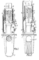
- the mechanism comprises a body of die cast construction including an integral mounting flange 1 by which the mechanism is secured to support structure, such as the framework of a vending machine.
- the body is extended both forwardly and rearwardly of the flange and forms a sliding guide track for a coin slide 2 of generally known form, having an aperture 3 for the insertion of coins.
- the particular slide mechanism shown is adapted for operation by 50P, 10P and 5P coins.
- the mechanism is designed to permit a full inward stroke of the coin slide 2, even if the coin (or token) fails any of the tests imposed upon it, or indeed if no coin or token is present. This characteristic reduces the temptation to use brute force on the coin slide, since it offers no great resistance to full inward travel.
- the mechanism relies for its operating or releasing function upon displacement of a secondary slide 4 which is yieldingly coupled to the coin slide, but is latched against completion of its operating movement until the coin has passed the various tests imposed on it.
- the coin slide 2 is urged outwardly relative to the body of the mechanism by a tension spring and has a set of ratchet teeth at its inner end for co-operation with a ratchet pawl, all in known manner.
- the secondary slide 4 is supported above the upper surface of the coin slide and is guided for longitudinal sliding movement relative to the coin slide. It is formed with a longitudinal slot 6 which receives the shoulder of an abutment formed by a shoulder screw 7 fast with the coin slide.
- An intermediate slide 8 is slidably mounted in turn on the secondary slide, to which it is coupled by tension springs 9 urging it outwardly, relative to the secondary slide.
- Longitudinal movement of the intermediate slide relative to the secondary slide is limited by four shoulder screws 11 secured to the secondary slide and engaging in longitudinal slots 12 formed in the intermediate slide.
- the screws 11 also provide for the location and sliding mounting of the slide 8 on slide 6.
- the intermediate slide is also formed with a central slot 13 aligned with the slot 6 of slide 8 so as to be engageable by the head of screw 7.
- Operating movement of the secondary slide 4 is controlled by the position of a lever 14 pivotally mounted on the main body adjacent one side of the secondary slide, and carrying a stop pin 15 for co-operation in different operative positions with different co-operating portions 16, 17, 18, 19 of the secondary slide constituted by a shoulder and slots or notches set at different distances along the length of the secondary slide.
- the lever 14 normally occupies the position shown in Figures 1 and 2, in which the stop pin 15 is aligned with a shoulder 16 on the slide 4. With the lever in this position, the slide 4 can travel no further inwardly than its position in Figure 2, which corresponds with the position in which the ratchet of the coin slide is engaged. This position of the lever 14 indicates that no coin is present, or that it is too small to displace the lever 14 sufficiently to permit further movement of the slide 4.
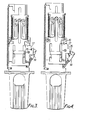
- the lever 14 is pivotable in a clockwise direction, to move the stop pin 15 laterally, in the plane of the secondary slide, in response to the passage of a coin through the diameter testing means.
- the lever is pivoted to the position shown in Figure 3, in which the pin 15 is aligned with a slot 17 in the secondary slide, which is therefore able to move inwardly until the pin is encountered by the closed outer end of the slot 17, at which point the secondary slide is locked against further displacement.
- the lever will be displaced at a greater angle, as illustrated in Figure 4, permitting a larger displacement of the secondary slide.
- the pin 15 is moved into alignment with a notch 19 on the outer edge of the secondary slide.
- a third slot 18 is provided to co-operate with the stop pin 15 when a smaller coin, say 2P or 5P is present.
- displacement of the secondary slide is made dependent upon the value of the coin in question and preferably, and as illustrated, the larger the value of the accepted coin the greater the displacement of the secondary slide.
- the mechanism can, of course, be designed to handle only one or two coins, or more than three different coins, subject to practical limitations imposed by the differences in diameter of the selection of coins in question.
- Displacement of the secondary slide can be employed to actuate, or release, the apparatus under control either by direct mechanical actuation, or indirectly by employing the displacement to operate e.g. limit switches and/or solenoids.
- the secondary slide may carry an electrical contact arranged to co-operate with a series of fixed contacts arranged alongside the slide. Bridging of the respective fixed contacts may of course be employed to actuate respective solenoids or equivalent electro-mechanical devices, or to generate pulsed signals fed to a totalizer.
- a succession of coins may be required to operate or release an apparatus.
- a price of, say, 80 pence may be charged.
- a suitable form of totalizer is required to count the total value of the coins inserted before the machine can be started.
- the coin slide 2 can be used to press the starter button each time the slide is pressed fully inwardly, but starting can be delayed by holding open a solenoid operated switch in series with the starter switch until the totalizer confirms full payment to actuate the solenoid.
Landscapes
- Physics & Mathematics (AREA)
- General Physics & Mathematics (AREA)
- Control Of Vending Devices And Auxiliary Devices For Vending Devices (AREA)
- Testing Of Coins (AREA)
- Telephone Set Structure (AREA)
Applications Claiming Priority (2)
| Application Number | Priority Date | Filing Date | Title |
|---|---|---|---|
| GB8331842 | 1983-11-29 | ||
| GB838331842A GB8331842D0 (en) | 1983-11-29 | 1983-11-29 | Coin slide mechanism |
Publications (2)
| Publication Number | Publication Date |
|---|---|
| EP0143635A2 true EP0143635A2 (de) | 1985-06-05 |
| EP0143635A3 EP0143635A3 (de) | 1987-04-15 |
Family
ID=10552532
Family Applications (1)
| Application Number | Title | Priority Date | Filing Date |
|---|---|---|---|
| EP84308184A Withdrawn EP0143635A3 (de) | 1983-11-29 | 1984-11-26 | Schiebervorrichtung für Münzen |
Country Status (4)
| Country | Link |
|---|---|
| US (1) | US4585111A (de) |
| EP (1) | EP0143635A3 (de) |
| CA (1) | CA1234324A (de) |
| GB (1) | GB8331842D0 (de) |
Family Cites Families (2)
| Publication number | Priority date | Publication date | Assignee | Title |
|---|---|---|---|---|
| DE1474795A1 (de) * | 1965-10-04 | 1969-07-10 | Johannes Jansen | Muenzapparat |
| US3605974A (en) * | 1969-11-12 | 1971-09-20 | Pyramid Mfg Co | Multiple coin actuating device |
-
1983
- 1983-11-29 GB GB838331842A patent/GB8331842D0/en active Pending
-
1984
- 1984-11-16 US US06/671,903 patent/US4585111A/en not_active Expired - Fee Related
- 1984-11-20 CA CA000468190A patent/CA1234324A/en not_active Expired
- 1984-11-26 EP EP84308184A patent/EP0143635A3/de not_active Withdrawn
Also Published As
| Publication number | Publication date |
|---|---|
| US4585111A (en) | 1986-04-29 |
| EP0143635A3 (de) | 1987-04-15 |
| GB8331842D0 (en) | 1984-01-04 |
| CA1234324A (en) | 1988-03-22 |
Similar Documents
| Publication | Publication Date | Title |
|---|---|---|
| US4298116A (en) | String detector for a coin-selecting device | |
| US4936436A (en) | Push coin acceptor | |
| US4033442A (en) | Locking and releasing mechanism for a vending machine | |
| US4585111A (en) | Coin slide mechanisms | |
| US2529196A (en) | Vending machine | |
| GB990926A (en) | Coin actuated merchandising apparatus | |
| US3776418A (en) | Selection system for vending machine | |
| US3741362A (en) | Alternating feed for coins or the like | |
| US2542034A (en) | Coin controlled mechanism | |
| US3887054A (en) | Coin slide mechanism | |
| US3797626A (en) | Credit register mechanism | |
| US3068984A (en) | Vending control apparatus | |
| GB1318567A (en) | Money handling device | |
| US5402871A (en) | Drop coin mechanism | |
| US3762526A (en) | Coin credit accumulating device | |
| US2067248A (en) | Coin control device | |
| US4509630A (en) | Multi-coin coin chute | |
| US2049527A (en) | Coin slot mechanism | |
| US3211161A (en) | Coin register | |
| US3155213A (en) | Money-handling devices | |
| US2621770A (en) | Coin controlled credit mechanism | |
| US2660284A (en) | Control apparatus for vending machines | |
| US3948380A (en) | Coin operated vending machine | |
| US3696905A (en) | Coin escrow means and circuit | |
| US4396105A (en) | Price setting mechanism for a vending machine |
Legal Events
| Date | Code | Title | Description |
|---|---|---|---|
| PUAI | Public reference made under article 153(3) epc to a published international application that has entered the european phase |
Free format text: ORIGINAL CODE: 0009012 |
|
| AK | Designated contracting states |
Designated state(s): DE FR GB SE |
|
| PUAL | Search report despatched |
Free format text: ORIGINAL CODE: 0009013 |
|
| AK | Designated contracting states |
Kind code of ref document: A3 Designated state(s): DE FR GB SE |
|
| 17P | Request for examination filed |
Effective date: 19871013 |
|
| 17Q | First examination report despatched |
Effective date: 19890816 |
|
| STAA | Information on the status of an ep patent application or granted ep patent |
Free format text: STATUS: THE APPLICATION HAS BEEN WITHDRAWN |
|
| 18W | Application withdrawn |
Withdrawal date: 19891206 |
|
| RIN1 | Information on inventor provided before grant (corrected) |
Inventor name: ALLEN, KENNETH RINALDO |