EP0143495B1 - Röntgenstrahlungsanalysierapparat mit Verwendung eines Abbeugungssystems - Google Patents
Röntgenstrahlungsanalysierapparat mit Verwendung eines Abbeugungssystems Download PDFInfo
- Publication number
- EP0143495B1 EP0143495B1 EP84201681A EP84201681A EP0143495B1 EP 0143495 B1 EP0143495 B1 EP 0143495B1 EP 84201681 A EP84201681 A EP 84201681A EP 84201681 A EP84201681 A EP 84201681A EP 0143495 B1 EP0143495 B1 EP 0143495B1
- Authority
- EP
- European Patent Office
- Prior art keywords
- ray
- detector
- analysis apparatus
- specimen
- collimator
- Prior art date
- Legal status (The legal status is an assumption and is not a legal conclusion. Google has not performed a legal analysis and makes no representation as to the accuracy of the status listed.)
- Expired
Links
- 238000002441 X-ray diffraction Methods 0.000 title claims description 10
- 239000000696 magnetic material Substances 0.000 claims description 17
- 239000002245 particle Substances 0.000 claims description 13
- 238000001514 detection method Methods 0.000 claims description 7
- 125000006850 spacer group Chemical group 0.000 claims description 4
- 238000004458 analytical method Methods 0.000 description 6
- 239000013078 crystal Substances 0.000 description 5
- 230000005855 radiation Effects 0.000 description 5
- 230000000694 effects Effects 0.000 description 3
- 238000001228 spectrum Methods 0.000 description 3
- 238000006073 displacement reaction Methods 0.000 description 2
- 238000002083 X-ray spectrum Methods 0.000 description 1
- 239000010405 anode material Substances 0.000 description 1
- 150000002500 ions Chemical class 0.000 description 1
- UGKDIUIOSMUOAW-UHFFFAOYSA-N iron nickel Chemical compound [Fe].[Ni] UGKDIUIOSMUOAW-UHFFFAOYSA-N 0.000 description 1
- 239000000463 material Substances 0.000 description 1
- 238000005259 measurement Methods 0.000 description 1
- 230000035945 sensitivity Effects 0.000 description 1
Images
Classifications
-
- G—PHYSICS
- G01—MEASURING; TESTING
- G01N—INVESTIGATING OR ANALYSING MATERIALS BY DETERMINING THEIR CHEMICAL OR PHYSICAL PROPERTIES
- G01N23/00—Investigating or analysing materials by the use of wave or particle radiation, e.g. X-rays or neutrons, not covered by groups G01N3/00 – G01N17/00, G01N21/00 or G01N22/00
- G01N23/20—Investigating or analysing materials by the use of wave or particle radiation, e.g. X-rays or neutrons, not covered by groups G01N3/00 – G01N17/00, G01N21/00 or G01N22/00 by using diffraction of the radiation by the materials, e.g. for investigating crystal structure; by using scattering of the radiation by the materials, e.g. for investigating non-crystalline materials; by using reflection of the radiation by the materials
- G01N23/207—Diffractometry using detectors, e.g. using a probe in a central position and one or more displaceable detectors in circumferential positions
Definitions
- the invention relates to an X-ray analysis apparatus, which comprises an X-ray source, a specimen carrier and an X-ray detector which is arranged, when viewed along the propagation direction of an X-ray beam generated in a specimen to be examined, beyond a collimating member for the X-ray beam.
- charged particles notably electrons which are generated, for example, by the X-ray beam and which penetrate the detector, have a disturbing effect.
- the charged particles cause a background signal which has a disturbing effect notably on the measurement of longwave length X-rays, i.e. during the analysis of specimens including elements having a comparatively low atomic number, because the detector entrance windows to be used in those circumstances, only absorb the particles to a small extent and the detection signal generated by each X-ray quantum is not substantially greater than that for said particle.
- Charged particles such as electrons and ions can be released by the X-ray beam from the specimen, and from irradiated structural parts of the apparatus such as an X-ray beam collimating member and the like.
- an X-ray analysis apparatus of the kind set forth is characterized in that either respective laminae of a laminated collimator can be maintained at different potentials or permanent magnetic material forms part of a laminae structure of a collimator in order to constitute a deflecting system for charged particles.
- the charged particles in an X-ray analysis apparatus in accordance with the invention are deflected away from the detector entrance, they will not form part of the detector signal; a substantial improvement in the signal-to-noise ratio of the detection signal will thus be obtained notably for the analysis of light elements.
- deflection takes place by means of a magnetic deflection field which is introduced into the X-ray beam path in front of the detector and whose extension to the specimen, the X-ray source and the detector is restricted by means of a magnetic shield.
- a magnetic deflection field which is introduced into the X-ray beam path in front of the detector and whose extension to the specimen, the X-ray source and the detector is restricted by means of a magnetic shield.
- permanent magentic material may be included in a locally arranged collimating member.
- the magnetic material may be included notably in the laminae which form a collimator, or take the place of the spacers between the laminae.
- Suitable shielding of the magnetic field is provided by a magnetic shield arranged about the collimator and comprising the permanent magnetic material.
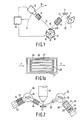
- Fig. 1 shows diagrammatically a sequential X-ray spectrometer, comprising an X-ray source 1 with a radiation filter 2, a specimen 4, a primary collimator 6, a crystal changer 8, which in this case comprises five different analyser crystals 10, and an X-ray detector 12 with a secondary collimator 14.
- the detector can be rotated about a point of rotation 16 in order to perform the required 2 ⁇ -type of displacement, so that an X-ray spectrum can be recorded.
- an electronic circuit 18 which is also capable of controlling the angular position of the detector with respect to the specimen.
- the appropriate radiaton spectrum for an X-ray beam 20 generated by the X-ray tube is provided for analysis by selection of the anode material, the high voltage used in the X-ray tube, and the filter 2 arranged in the beam path.
- the X-ray beam 20 causes fluorescence in the specimen.
- An X-ray beam 22 thus generated contains a pattern of radiation which is characteristic of elements in the specimen.
- the various characteristic radiation peaks in a beam 24 are spatially separated viewed through the angle ⁇ , by diffraction at an analyser cyrstal 10. This spectrum can subsequently be measured by means of the detector.
- a deflection system for changed particles is added to the collimator 14 in this embodiment.
- the collimator is enclosed by a shielding cage 26 which consists of, for example, nickel-iron.
- a shielding cage 26 which consists of, for example, nickel-iron.
- the direction of a magnetic deflection field H is shown in Figure 1a for an X-ray beam direction perpendicular with respect to the plane of the drawing of Figure 1a.
- the permanent magnetic material is included in the laminar structure of the collimator. This can be achieved, for example, by making each lamina 27, or some of the laminae, of a permanent magnetic material or by adding a permanent magnetic material thereto.
- spacers 28 between the laminae of the collimator are made of a permanent magnetic material.
- Fig. 2 diagrammatically shows a simultaneous X-ray spectrometer which comprises an X-ray source 30, a specimen 32, a first detection system 34 with a primary radiation gap 36, an analysis crystal 38 which is curved in this case, and a detector 40 with a secondary radiation gap 42 and a second detection system 44 with an analysis crystal 46, which is flat in this case, a primary collimator 48, and a detector 50 with a secondary collimator 52.
- a permanent magnetic material for the lateral deflection of the electrons present in a space 54; consequently, these electrons will not pass through the detector gap 42.
- the permanent magnetic material is in this case formed, for example by two magnets 56.
- a magnetic shield 58 of a soft magnetic material is again arranged about the collimating member incorporating the permanent magnetic material.
- a collimator 52 of the second detection system 44 can also be provided with a magnetic deflection system as described with reference to Fig. 1a; a permanent magnetic material is then preferably incorporated in the collimator, for example, in the form of permanent magnetic spacers between the laminae.
- the collimator incorporating the magnetic material is, in similar manner, shielded against stray fields by means of a shielding sleeve 64 of a soft-magnetic material.
- Electrostatic deflection can also be performed in an electromagnetic or an electrostatic manner similar to that described for a magnetic deflection system.
- laminae of a collimator are preferably maintained at different potentials. Consequently, the laminae must be electrically insulated from one another and be provided with supply leads.
- Electrostatic deflection has the advantage that a higher degree of freedom exists as regards the adjustment of the intensity of the deflection field; it is a drawback, however, in that the presence of supply leads is often inconvenient.
- a high degree of freedom of adjustment is also obtained in the case of electromagnetic deflection utilizing, for example a magnetic coil whose field is effective in the vicinity of the collimating member.
Landscapes
- Chemical & Material Sciences (AREA)
- Crystallography & Structural Chemistry (AREA)
- Physics & Mathematics (AREA)
- Health & Medical Sciences (AREA)
- Life Sciences & Earth Sciences (AREA)
- Analytical Chemistry (AREA)
- Biochemistry (AREA)
- General Health & Medical Sciences (AREA)
- General Physics & Mathematics (AREA)
- Immunology (AREA)
- Pathology (AREA)
- Analysing Materials By The Use Of Radiation (AREA)
Claims (5)
Applications Claiming Priority (2)
| Application Number | Priority Date | Filing Date | Title |
|---|---|---|---|
| NL8304009A NL8304009A (nl) | 1983-11-22 | 1983-11-22 | Roentgen analyse apparaat met afbuigsysteem. |
| NL8304009 | 1983-11-22 |
Publications (3)
| Publication Number | Publication Date |
|---|---|
| EP0143495A2 EP0143495A2 (de) | 1985-06-05 |
| EP0143495A3 EP0143495A3 (en) | 1985-07-03 |
| EP0143495B1 true EP0143495B1 (de) | 1989-11-08 |
Family
ID=19842753
Family Applications (1)
| Application Number | Title | Priority Date | Filing Date |
|---|---|---|---|
| EP84201681A Expired EP0143495B1 (de) | 1983-11-22 | 1984-11-20 | Röntgenstrahlungsanalysierapparat mit Verwendung eines Abbeugungssystems |
Country Status (6)
| Country | Link |
|---|---|
| EP (1) | EP0143495B1 (de) |
| JP (1) | JPS60125549A (de) |
| AU (1) | AU572917B2 (de) |
| CA (1) | CA1237830A (de) |
| DE (1) | DE3480426D1 (de) |
| NL (1) | NL8304009A (de) |
Families Citing this family (2)
| Publication number | Priority date | Publication date | Assignee | Title |
|---|---|---|---|---|
| GB2442485B (en) | 2006-10-03 | 2008-12-10 | Thermo Electron Corp | X-ray photoelectron spectroscopy analysis system for surface analysis and method therefor |
| CN114062406B (zh) * | 2022-01-04 | 2022-03-22 | 中国工程物理研究院流体物理研究所 | 时间分辨多晶x射线衍射靶装置 |
Citations (1)
| Publication number | Priority date | Publication date | Assignee | Title |
|---|---|---|---|---|
| US852594A (en) * | 1906-02-05 | 1907-05-07 | Frederick C Berwick | Nautical signal. |
Family Cites Families (6)
| Publication number | Priority date | Publication date | Assignee | Title |
|---|---|---|---|---|
| US3471694A (en) * | 1965-03-01 | 1969-10-07 | Philips Electronics & Pharm In | Charge particle barrier consisting of magnetic means for removing electrons from an x-ray beam |
| DE1265450B (de) * | 1965-10-25 | 1968-04-04 | Siemens Ag | Anordnung zur Beseitigung von Untergrundstrahlung in einem Roentgenspektrometer |
| JPS528118B2 (de) * | 1972-03-22 | 1977-03-07 | ||
| US3852594A (en) * | 1973-07-25 | 1974-12-03 | Pepi Inc | X-ray diffraction apparatus |
| JPS56103379A (en) * | 1980-01-22 | 1981-08-18 | Horiba Ltd | Semiconductor x-ray detector |
| JPS59141045A (ja) * | 1983-01-31 | 1984-08-13 | Shimadzu Corp | X線分析装置 |
-
1983
- 1983-11-22 NL NL8304009A patent/NL8304009A/nl not_active Application Discontinuation
-
1984
- 1984-11-19 JP JP24254284A patent/JPS60125549A/ja active Pending
- 1984-11-19 CA CA000468125A patent/CA1237830A/en not_active Expired
- 1984-11-20 AU AU35711/84A patent/AU572917B2/en not_active Ceased
- 1984-11-20 DE DE8484201681T patent/DE3480426D1/de not_active Expired
- 1984-11-20 EP EP84201681A patent/EP0143495B1/de not_active Expired
Patent Citations (1)
| Publication number | Priority date | Publication date | Assignee | Title |
|---|---|---|---|---|
| US852594A (en) * | 1906-02-05 | 1907-05-07 | Frederick C Berwick | Nautical signal. |
Also Published As
| Publication number | Publication date |
|---|---|
| EP0143495A2 (de) | 1985-06-05 |
| DE3480426D1 (en) | 1989-12-14 |
| JPS60125549A (ja) | 1985-07-04 |
| NL8304009A (nl) | 1985-06-17 |
| AU3571184A (en) | 1985-05-30 |
| AU572917B2 (en) | 1988-05-19 |
| EP0143495A3 (en) | 1985-07-03 |
| CA1237830A (en) | 1988-06-07 |
Similar Documents
| Publication | Publication Date | Title |
|---|---|---|
| Folkmann | Analytical use of ion-induced X-rays | |
| US5293414A (en) | Nuclear resonances in activation analysis, and particularly, its application to detection of nitrogen based explosives in luggage | |
| Forck | Beam instrumentation and diagnostics | |
| EP0137650B1 (de) | Energiespektrometer für geladene Teilchen | |
| US4255656A (en) | Apparatus for charged particle spectroscopy | |
| EP0143495B1 (de) | Röntgenstrahlungsanalysierapparat mit Verwendung eines Abbeugungssystems | |
| US3471694A (en) | Charge particle barrier consisting of magnetic means for removing electrons from an x-ray beam | |
| US3376415A (en) | X-ray spectrometer with means to vary the spacing of the atomic planes in the analyzing piezoelectric crystal | |
| Dichter et al. | High energy electron fluxmeter | |
| Siegbahn et al. | An Electron Pair Spectrometer of Lens Type for Hard Gamma‐Radiation | |
| US3612875A (en) | Mossbauer spectrometer | |
| US20250172513A1 (en) | Handheld X-ray fluorescence, XRF, analyzer and a method for elemental analysis with a handheld XRF analyzer | |
| Jean-Marie | A source of monoenergetic electrons of 0.5 to 3.5 MeV for scintillation counter studies | |
| Asoka-Kumar et al. | An intense monoenergetic positron beam with an adjustable energy between 0.5 and 3.0 MeV | |
| Yeremin et al. | Spectroscopy of the Isotopes of Transfermium Elements in Dubna: Current Status and Prospects | |
| EP0554935A1 (de) | Kombiniertes Röntgenspektrometer | |
| JPS59141045A (ja) | X線分析装置 | |
| Forck | Measurement Techniques for Transfer Lines and Beam Instrumentation | |
| US4393306A (en) | Radiation detector | |
| GB1600440A (en) | Multi-channel x-ray detector | |
| Buechner et al. | Excited States of K 40 | |
| Olivier et al. | An investigation into the possible use of the nuclear microprobe for the examination of surface topography | |
| Bombarda et al. | γ-Background discrimination in position-encoding x-ray proportional counters | |
| Hemmendinger et al. | TIME-OF-FLIGHT NEUTRON CROSS-SECTION MEASUREMENTS MADE WITH NEUTRONS FROM NUCLEAR EXPLOSIONS. | |
| Fox et al. | Low-Energy Proton Production by 160-Mev Protons |
Legal Events
| Date | Code | Title | Description |
|---|---|---|---|
| PUAI | Public reference made under article 153(3) epc to a published international application that has entered the european phase |
Free format text: ORIGINAL CODE: 0009012 |
|
| PUAL | Search report despatched |
Free format text: ORIGINAL CODE: 0009013 |
|
| AK | Designated contracting states |
Designated state(s): DE FR GB NL |
|
| AK | Designated contracting states |
Designated state(s): DE FR GB NL |
|
| 17P | Request for examination filed |
Effective date: 19851220 |
|
| 17Q | First examination report despatched |
Effective date: 19870605 |
|
| GRAA | (expected) grant |
Free format text: ORIGINAL CODE: 0009210 |
|
| AK | Designated contracting states |
Kind code of ref document: B1 Designated state(s): DE FR GB NL |
|
| PG25 | Lapsed in a contracting state [announced via postgrant information from national office to epo] |
Ref country code: NL Effective date: 19891108 |
|
| REF | Corresponds to: |
Ref document number: 3480426 Country of ref document: DE Date of ref document: 19891214 |
|
| ET | Fr: translation filed | ||
| NLV1 | Nl: lapsed or annulled due to failure to fulfill the requirements of art. 29p and 29m of the patents act | ||
| PLBE | No opposition filed within time limit |
Free format text: ORIGINAL CODE: 0009261 |
|
| STAA | Information on the status of an ep patent application or granted ep patent |
Free format text: STATUS: NO OPPOSITION FILED WITHIN TIME LIMIT |
|
| 26N | No opposition filed | ||
| REG | Reference to a national code |
Ref country code: FR Ref legal event code: CD |
|
| PGFP | Annual fee paid to national office [announced via postgrant information from national office to epo] |
Ref country code: GB Payment date: 19961101 Year of fee payment: 13 |
|
| PGFP | Annual fee paid to national office [announced via postgrant information from national office to epo] |
Ref country code: FR Payment date: 19961119 Year of fee payment: 13 |
|
| PGFP | Annual fee paid to national office [announced via postgrant information from national office to epo] |
Ref country code: DE Payment date: 19970127 Year of fee payment: 13 |
|
| PG25 | Lapsed in a contracting state [announced via postgrant information from national office to epo] |
Ref country code: GB Free format text: LAPSE BECAUSE OF NON-PAYMENT OF DUE FEES Effective date: 19971120 |
|
| PG25 | Lapsed in a contracting state [announced via postgrant information from national office to epo] |
Ref country code: FR Free format text: THE PATENT HAS BEEN ANNULLED BY A DECISION OF A NATIONAL AUTHORITY Effective date: 19971130 |
|
| GBPC | Gb: european patent ceased through non-payment of renewal fee |
Effective date: 19971120 |
|
| PG25 | Lapsed in a contracting state [announced via postgrant information from national office to epo] |
Ref country code: DE Free format text: LAPSE BECAUSE OF NON-PAYMENT OF DUE FEES Effective date: 19980801 |
|
| REG | Reference to a national code |
Ref country code: FR Ref legal event code: ST |