EP0142864A2 - X-ray diagnostic apparatus utilizing x-ray shield member - Google Patents
X-ray diagnostic apparatus utilizing x-ray shield member Download PDFInfo
- Publication number
- EP0142864A2 EP0142864A2 EP19840114043 EP84114043A EP0142864A2 EP 0142864 A2 EP0142864 A2 EP 0142864A2 EP 19840114043 EP19840114043 EP 19840114043 EP 84114043 A EP84114043 A EP 84114043A EP 0142864 A2 EP0142864 A2 EP 0142864A2
- Authority
- EP
- European Patent Office
- Prior art keywords
- ray
- scattered
- shield member
- arithmetic operation
- components
- Prior art date
- Legal status (The legal status is an assumption and is not a legal conclusion. Google has not performed a legal analysis and makes no representation as to the accuracy of the status listed.)
- Withdrawn
Links
- 230000005540 biological transmission Effects 0.000 claims abstract description 45
- 238000000034 method Methods 0.000 claims abstract description 15
- 230000002411 adverse Effects 0.000 claims abstract description 8
- 238000009826 distribution Methods 0.000 claims description 28
- 230000015654 memory Effects 0.000 claims description 18
- 239000000463 material Substances 0.000 claims description 4
- 230000000903 blocking effect Effects 0.000 claims description 3
- 238000001514 detection method Methods 0.000 claims description 3
- 230000035515 penetration Effects 0.000 claims description 3
- 239000011159 matrix material Substances 0.000 claims description 2
- 229920003002 synthetic resin Polymers 0.000 claims description 2
- 239000000057 synthetic resin Substances 0.000 claims description 2
- 230000000694 effects Effects 0.000 abstract description 5
- 238000004364 calculation method Methods 0.000 description 4
- 230000008030 elimination Effects 0.000 description 4
- 238000003379 elimination reaction Methods 0.000 description 4
- 238000013459 approach Methods 0.000 description 3
- 230000008901 benefit Effects 0.000 description 3
- 238000003745 diagnosis Methods 0.000 description 3
- 238000010586 diagram Methods 0.000 description 3
- 230000006870 function Effects 0.000 description 2
- 241000157282 Aesculus Species 0.000 description 1
- MBIVNOSUFDXRMI-JKJWBTBISA-N C[C@@H](C1)C2[IH]C1CC(C)(C)C(C)C2C Chemical compound C[C@@H](C1)C2[IH]C1CC(C)(C)C(C)C2C MBIVNOSUFDXRMI-JKJWBTBISA-N 0.000 description 1
- 230000005680 Thomson effect Effects 0.000 description 1
- 230000008859 change Effects 0.000 description 1
- 238000006243 chemical reaction Methods 0.000 description 1
- 238000005516 engineering process Methods 0.000 description 1
- 238000005286 illumination Methods 0.000 description 1
- 230000003993 interaction Effects 0.000 description 1
- 238000005259 measurement Methods 0.000 description 1
- 238000012986 modification Methods 0.000 description 1
- 230000004048 modification Effects 0.000 description 1
- 229920005989 resin Polymers 0.000 description 1
- 239000011347 resin Substances 0.000 description 1
- 238000006467 substitution reaction Methods 0.000 description 1
Images


Classifications
-
- H—ELECTRICITY
- H04—ELECTRIC COMMUNICATION TECHNIQUE
- H04N—PICTORIAL COMMUNICATION, e.g. TELEVISION
- H04N5/00—Details of television systems
- H04N5/30—Transforming light or analogous information into electric information
- H04N5/32—Transforming X-rays
-
- A—HUMAN NECESSITIES
- A61—MEDICAL OR VETERINARY SCIENCE; HYGIENE
- A61B—DIAGNOSIS; SURGERY; IDENTIFICATION
- A61B17/00—Surgical instruments, devices or methods, e.g. tourniquets
- A61B17/56—Surgical instruments or methods for treatment of bones or joints; Devices specially adapted therefor
-
- A—HUMAN NECESSITIES
- A61—MEDICAL OR VETERINARY SCIENCE; HYGIENE
- A61B—DIAGNOSIS; SURGERY; IDENTIFICATION
- A61B6/00—Apparatus or devices for radiation diagnosis; Apparatus or devices for radiation diagnosis combined with radiation therapy equipment
-
- A—HUMAN NECESSITIES
- A61—MEDICAL OR VETERINARY SCIENCE; HYGIENE
- A61B—DIAGNOSIS; SURGERY; IDENTIFICATION
- A61B6/00—Apparatus or devices for radiation diagnosis; Apparatus or devices for radiation diagnosis combined with radiation therapy equipment
- A61B6/06—Diaphragms
-
- A—HUMAN NECESSITIES
- A61—MEDICAL OR VETERINARY SCIENCE; HYGIENE
- A61B—DIAGNOSIS; SURGERY; IDENTIFICATION
- A61B6/00—Apparatus or devices for radiation diagnosis; Apparatus or devices for radiation diagnosis combined with radiation therapy equipment
- A61B6/52—Devices using data or image processing specially adapted for radiation diagnosis
- A61B6/5258—Devices using data or image processing specially adapted for radiation diagnosis involving detection or reduction of artifacts or noise
- A61B6/5282—Devices using data or image processing specially adapted for radiation diagnosis involving detection or reduction of artifacts or noise due to scatter
Definitions
- This invention generally relates to an X-ray diagnostic apparatus in which a transmitted X-ray image of an object to be examined, e.g., a patient, is available for diagnostic purposes, and more particularly, to an X-ray diagnostic apparatus by which visible X-ray images of the object can be obtained, based only upon primary X-rays, without any adverse influences caused by the scattered X-rays.
- X-rays incident on an X-ray detector through the object such as a patient contain not only primary X-rays but also X-rays which are scattered by the object under examination.'
- the scattered X-rays constitute one of the major causes of deteriorated contrast and resolution in the transmitted X-ray image. This makes it necessary to eliminate an image component on the scattered X-rays from the transmitted X-ray image data as sensed and provided by the detector.
- One of the approaches to eliminate the scattered X-ray component is to use a so-called “Buckey Blade” or an elimination grid for the scattered X-rays (referred to as a "grid”).
- This approach newly involves a problem in that there is a limit in the scattered X-ray elimination, because the grid per se scattered the X-rays incident thereupon.
- the elimination of the scattered X-rays is very significant in the field of X-ray diagnosis for the reasons that it improves an image quality, such as contrast and resolution, and thus allows a logarithm conversion of primary X-rays image data, thereby obtaining an accurate attenuation quantity of X-rays caused when the X-rays pass through the object.
- Many studies have been made on the scattered X-rays, aiming at their effective elimination.
- the complicated phenomena of the scattered X-rays impede or almost reject a theoretical approach to this theme. This is the present stage of technology in this field.
- an object of the present invention is to provide, by introducing a novel technical idea, an X-ray diagnositic apparatus which can effectively eliminate the scattered X-ray image component from the transmitted X-ray image components as obtained by the X-ray detector.
- the object of.the present invention may be accomplished by providing an X-ray diagnostic apparatus comprising:
- X-rays incident on the object such as a patient, under examination are generally classified into primary X-rays which directly transmit through the object and enter into an X-ray detector, and X-rays absorbed or scattered by the object through interactions of the X-rays with atoms constituting the object. Those scattered ones are called "scattered X-rays".
- some causes for the scattered X-rays are known, for example, photoelectric effects, Compton effects, Thomson effects, and the like. These phenomena cooperate to cause the scattered X-rays to have adverse effects on the transmitted X-ray image to be described later.
- the scattered X-rays incident on the X-ray detector experience multi- scattering within the object, it is very difficult to exactly grasp an intensity and a spatial spread of an incident X-ray beam. This phenomenon is explained as follows.
- Fig. 1 schematically illustrates how an X-ray radiated from an X-ray source 11, such as an X-ray tube, is scattered within an object 12 under examination and reaches an X-ray detector 13, while depicting a spatial spread with respect to detecting positions of the X-ray detector.
- Fig. 2 illustrates an X-ray intensity distribution over the detecting positions of the X-ray detector.
- Fig. 2 illustrates an X-ray intensity distribution over the detecting positions of the X-ray detector 13. As seen from Fig.
- a narrow spread, or spatial distribution of a sharp peak (as indicated by character K), located substantially at the center of the distribution curve, is caused by an inherent matter of the diagnosis system, for example, an X-ray focal spot and a wide spread (as indicated by character L) is caused by the scattered X-rays.
- a spatial distribution of the scattered X-rays is graphically shown.
- Fig. 3A a narrow X-ray beam is projected toward a body 14.
- Fig. 3B spatial distributions of the respective scattered X-rays are graphically shown.
- Fig. 3C an actual spatial distribution of the scattered X-rays is graphically shown, that is obtained by summing these spatial distributions.
- the characters "-a” and "a” define an area projected by the X-rays (referred to as an "X-ray projection area") on the detecting positions of the X-ray detector 13.
- the symbol “Isc(x)" denotes an intensity of the scattered X-rays. For convenience and clarity of illumination, these drawings are illustrated in one dimension.
- a total X-ray intensity distribution Im(x, y) incident on the detector is the sum of the primary X-ray intensity distribution Ip(x, y) and the scattered X-ray intensity distribution Ip(x, y) and is given by: where (x, y) indicates coordinates for representing positions on the X-ray, detector 13.
- the basic of the present invention can be realized based upon the above-described recognition.
- the X-ray is projected toward the object under examination in such a way that an X-ray shield member is interposed between the X-ray source and the X-ray detector within the X-ray projection area.
- the X-ray projection area is defined by projecting the X-ray from the X-ray source to the X-ray detector through the object.
- first transmitted X-ray image data obtained by the detector may contain theoretically the scattered X-ray components only, because the primary X-ray components have been shielded by the X-ray shield member before reaching the X-ray detector.
- Second transmitted X-ray image data is acquired under the condition that the X-ray shield member is removed from the X-ray projection area.
- the second image data contains not only the scattered X-ray components but also the primary X-ray components.
- subtracting the first image data from the second image data enables desirable image data to be calculated in accordance with the equation 1.
- This desirable image data involves only the primary X-ray components.
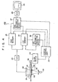
- An X-ray source 30 generates X-rays that are projected through an X-ray diaphragm 32 toward a patient 34 under examination.
- the patient 32 lies down on a couch 36.
- the X-ray projection area of the X-ray source 30 is denoted by reference numeral 38, that is defined by projecting the X-ray from the X-ray source 30 to the X-ray detector 22 through the patient 34.
- An X-ray shield member 50 is provided under the couch 36. In other words, it is positioned in front of the patient 34 along the X-ray path. This shield member 50 is designed to be slidable in parallel to the patient 34 or the couch 36. The slide operation into the X-ray projection area 38 will be described layer. A slide direction is indicated by an arrow 52.
- a system control unit 20 is provided with the X-ray diagnostic apparatus 100.
- a slide device 54 can mechanically slide the X-ray shield member 50 along the slide direction 52 under the control of the system control unit 20.
- An X-ray detector 22 is positioned behind the patient 34 along the X-ray path within the X-ray projection area 38. Outputs of the detector 22 are fed to an analogue-to-digital converter (A/D converter) 23.
- A/D converter an analogue-to-digital converter
- first and second memories 24 and 25 are connected to the A/D converter 23.
- the first memory 24 is communicated with a first arithmetic operation device 26 and the second memory 25 is communicated with a second arithmetic operation device 27.
- first and second memories 24, 25, and first and second arithmetic operation devices 26, 27 are controlled by the system control unit 20. Outputs of the second arithmetic operation device 27 are fed to a digital-to-analogue converter (D/A converter) 28.
- the D/A converter 28 is connected to a TV monitor 29.
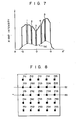
- the intensity distribution of the transmitted X-ray image signal is obtained by projecting the X-ray toward the object 34, that is shown by a graphic representation of Fig. 7.
- This intensity distribution Isc represents one which is taken along the lines A-A' on the surface of the X-ray detector 22.
- the intensity levels of those positions where the lead pieces 56 are positioned (indicated by numerical references 1, 2, 3, 4, and 5) steeply drop. Consequently, these intensity levels indicate the intensity of the scattered X-ray components Isc, because the primary X-ray components are blocked by those lead pieces 56.
- the X-ray source 30 is evergized to project the X-ray toward the patient 34 while the X-ray shield member 50 is slid along the longitudinal axis of the couch 36 and positioned within the X-ray projection area 38 by means of the slide device 54.
- the slide device 54 is controlled by the system control unit 20.
- the X-ray transmitted through the patient 34 is incident, as the X-ray image upon the X-ray detector 22 such as an image intensifier.
- the X-ray image is converted into an analogue X-ray transmission image signal. Thereafter, it is converted by the A/D converter 23 into corresponding digital transmission data.
- the digital transmission data is temporarily stored as first X-ray transmission data in the first memory 24.
- the amount of the scattered X-ray components over the entire pixels can be calculated by the first arithmetic operation device 26 in such a manner that the amount of the scattered X-ray components for the respective pixels is obtained by the internal interpolation method based upon the actual amount of the scattered X-ray components with respect to positions where the lead pieces 56 are present.
- the resultant data is stored in the first memory 24, that represents the intensity distribution of scattered X-ray components.
- X-ray transmission data is temporarily stored as second X-ray transmission data in the second memory 25.
- both the calculated data stored in the first memory 24 and the second X-ray transmission data are read from the respective memories 24 and 25 to the second arithmetic operation device 27.
- the function of this device 27 is as follows.
- the data representing the intensity distribution of the scattered X-ray components Isc is subtracted from the second X-ray transmission data so as to derive X-ray transmission data containing only the primary X-ray components. In other words, this resultant data excludes the scattered X-ray components.
- the finally-obtained transmission data is digital-to-analogue converted in the D/A converter 28, and is displayed in the TV monitor 29.
- the displayed X-ray image has high image qualities, i.e., better contrast and resolution.
- Such an advantage of the invention is caused for the following reason.
- the amount of the scattered X-ray components is calculated in the first arithmetic operation device 26 based upon the first X-ray transmission data that has been taken by partially blocking the penetration of the X-ray by inserting the X-ray shield member 50 into the X-ray projection area 38.
- the resultant data involves only the intensity distribution of the scattered X-ray components Isc.
- This data is then subtracted from the second X-ray transmission data that has been taken by extracting the X-ray shield member 50 from the X-ray projection area 38, so that the finally-obtained transmission data contains only the primary X-ray components. Accordingly, the X-ray transmission image displayed on the TV monitor 29 has no adverse influence caused by the scattered X-ray components.
- Fig. 8 shows an image pattern caused by the X-ray shield member 50, which is obtained by the X-ray detector 22, e.g., the image intensifier tube (not shown) and stored in the first memory 24.
- the shadow indicated by numbers P 11 , P 12 , ..., P55 corresponds to the images defined by the lead pieces 56 of the X-ray shield member 50.
- a line 82 parallel to the abscessa passes through the shadow P 21 , P 22 , P 23 , P 24 and P 25 .
- a line 83 parallel to the abscessa passes through the shadow P 31' P 32 , P 33 , P 34 and P 35 . Fi g.
- FIG. 9 shows intensity distributions of the scattered X-ray components along the lines 82 and 83, which have been obtained by utilizing the linear interpolation method.
- the abscessa represents pixel numbers, and the ordinate indicates X-ray intensities.
- a value Dij (ij are for example 31 and 25) represents the intensity of the scattered X-ray component of the above-described images Pij (ij are for instance 11 and 55). This intensity is obtained from the actual measurement as previously described with respect to Fig. 7.
- the intensities between two adjacent values, e.g., D 22 and D 23 are calculated by utilizing the following linear interpolation method.
- Fig. 10 shows a region surrounded by the shadow P 22' P 23' P 32 and P 33 corresponding to the actual values D 22 , D 23 , D 32 and D 33 .
- the following calculation on the linear interpolation method is directed to interpolation data for each of the pixels in the region.
- a first linear interpolation is carried out for obtaining the interpolation data of the pixels along the line across .the actual values D 22 and D 23 . That is, the desired interpolation data of the arbitrary pixel X 2 j (i.e., the intensity of the scattered X -ray component thereof) can be calculated by the following equation: where X 22 and X 23 denote the pixel numbers of the shadow P 22 and P 23 shown in F ig. 8.
- the interpolation data (the scattered X-ray intensities) of all of the pixels located in the region defined by the actual values D 22' D 23 , D 32 and D33 can be easily obtained by employing two sets of the interpolation data that have been calculated from the equations 2 and 3.
- the interpolation data of the pixel Xij parallel to the ordinate is calculated based on two sets of the data d(X 2 j) and d(X 3j ) of the pixels X 2j and X 3 j as follows:
- the other interpolation data of all pixels surrounded by the four corner shadow P 11 , P 15 , P 51 and P 55 can be calculated by introducing the above calculation method.
- such an interpolation calculation cannot be directly applied to the remaining pixels located outside the region defined by the corner shadow P 11 , P 15 , P 51 and P 55 .
- the interpolation data for the pixels located on the lines which intersect the above shadow P 11 , P 151 P 51 and P 55 may be used as the desired interpolation data (as indicated by, for example, a horizontal line connecting the actual value D 21 and the ordinate).
- the entire intensity amounts of the scattered X-rays can be calculated for the storage region of the first memory 24 (512 x 512 pixel numbers), whereby the desired spatial distribution of the X-ray intensity can be obtained.
- the resultant intensity amounts are stored as the first X-ray transmission data in the first memory 24.
- the scattered X-ray image data is obtained by interposing the X-ray shield member 50 between the X-ray source 30 and the X-ray detector 22 within the X-ray projection area 38.
- the data representing the scattered X-ray components is then calculated from the first X-ray transmission data by utilizing the linear interpolation method.
- the second X - ray transmission data is obtained by removing the X-ray shield member 50 from the X-ray projection area 38. Then the subtraction is effected between the data representing the scattered X-ray components and the second X-ray transmission data so as to obtain the X-ray image data having the better image qualities.
- the advantage of this embodiment is that the acquisition of the X-ray image data without any adverse effect.by the scattered X-ray components can be achieved.
- the first X-ray transmission data was obtained by inserting the X-ray shield member into the X-ray projection area and thereafter, the second X-ray transmission data was obtained by removing it from the X-ray projection area. It is also possible to change the sequence of the X-ray data acquisition.
- the X-ray shield member may be interposed between the patient 34 and the X-ray source 30.
- the linear interpolation method may be, of course, substituted by, for example, utilizing the spline function.
Landscapes
- Health & Medical Sciences (AREA)
- Life Sciences & Earth Sciences (AREA)
- Engineering & Computer Science (AREA)
- Medical Informatics (AREA)
- Surgery (AREA)
- Public Health (AREA)
- Veterinary Medicine (AREA)
- Heart & Thoracic Surgery (AREA)
- Nuclear Medicine, Radiotherapy & Molecular Imaging (AREA)
- Molecular Biology (AREA)
- Animal Behavior & Ethology (AREA)
- General Health & Medical Sciences (AREA)
- Biomedical Technology (AREA)
- Biophysics (AREA)
- Physics & Mathematics (AREA)
- High Energy & Nuclear Physics (AREA)
- Optics & Photonics (AREA)
- Pathology (AREA)
- Radiology & Medical Imaging (AREA)
- Multimedia (AREA)
- Signal Processing (AREA)
- Computer Vision & Pattern Recognition (AREA)
- Orthopedic Medicine & Surgery (AREA)
- Apparatus For Radiation Diagnosis (AREA)
- Analysing Materials By The Use Of Radiation (AREA)
- Closed-Circuit Television Systems (AREA)
Abstract
Description
- This invention generally relates to an X-ray diagnostic apparatus in which a transmitted X-ray image of an object to be examined, e.g., a patient, is available for diagnostic purposes, and more particularly, to an X-ray diagnostic apparatus by which visible X-ray images of the object can be obtained, based only upon primary X-rays, without any adverse influences caused by the scattered X-rays.
- Generally, in the X-ray diagnostic apparatus set forth in the preamble, X-rays incident on an X-ray detector through the object such as a patient contain not only primary X-rays but also X-rays which are scattered by the object under examination.' The scattered X-rays constitute one of the major causes of deteriorated contrast and resolution in the transmitted X-ray image. This makes it necessary to eliminate an image component on the scattered X-rays from the transmitted X-ray image data as sensed and provided by the detector.
- One of the approaches to eliminate the scattered X-ray component is to use a so-called "Buckey Blade" or an elimination grid for the scattered X-rays (referred to as a "grid"). This approach newly involves a problem in that there is a limit in the scattered X-ray elimination, because the grid per se scattered the X-rays incident thereupon.
- The elimination of the scattered X-rays is very significant in the field of X-ray diagnosis for the reasons that it improves an image quality, such as contrast and resolution, and thus allows a logarithm conversion of primary X-rays image data, thereby obtaining an accurate attenuation quantity of X-rays caused when the X-rays pass through the object. Many studies have been made on the scattered X-rays, aiming at their effective elimination. The complicated phenomena of the scattered X-rays impede or almost reject a theoretical approach to this theme. This is the present stage of technology in this field.
- For the above background reasons, an object of the present invention is to provide, by introducing a novel technical idea, an X-ray diagnositic apparatus which can effectively eliminate the scattered X-ray image component from the transmitted X-ray image components as obtained by the X-ray detector.
- The object of.the present invention may be accomplished by providing an X-ray diagnostic apparatus comprising:
- an X-ray source for successively generating X-rays;
- an X-ray detector for detecting an X-ray image of an object under examination by projecting the X-rays from the X-ray source toward the object, and for converting the detected image into X-ray transmission signals;
- an analogue-to-digital converter for converting the X-ray transmission signals into corresponding digital transmission data;
- an X-ray shield member having a plurality of X-ray shield materials,. for partially blocking the penetration of the X-rays over an X-ray projection area defined by projecting the X-rays from the X-ray source to the X-ray detection means through the object;
- a first memory for storing at least first X-ray transmission data acquired during a first X-ray projection period under the condition that the X-ray shield member is inserted into the X-ray projection area;
- a first arithmetic operation device for obtaining data representing an intensity distribution of scattered X-ray components, based upon the first transmission data over the entire X-ray projection area by way of an interpolation method;
- a second memory for storing at least second transmission data acquired during a second X-ray projection period under the condition that the X-ray shield member is removed from the X-ray projection area; and
- a second arithmetic operation device for subtracting said data representing the intensity distribution of scattered X-ray components from the second transmission data, thereby obtaining X-ray transmission data having no adverse influence by the scattered X-ray components.
- The particular advantage is obtained in that since the X-ray transmission image having no adverse influence caused by the scattered X-ray components, can be displayed, the resultant image of the object has better contrast and resolution. As a result, such an X-ray diagnostic apparatus according to the invention can provide a precise and excellent diagnosis.
- This and other objects and features of the present invention may be best understood by reference to the specification and the accompanying drawings, in which;
- Fig. 1 is an illustration for explaining an occurrence of scattered X-rays when an X-ray is projected toward an object under examination;
- Fig. 2 shows a graphic representation on an X-ray intensity vs. a detection position on an X-ray detector;
- Figs 3A, 3B and 3C graphically illustrate a spatial distribution of the scattered X-rays' intensity;
- Fig. 4 shows a schematic block diagram of an X-ray diagnostic apparatus according to one preferred embodiment;
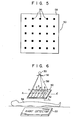
- Fig. 5 schematically shows a front view of an X-ray shield member;
- Fig. 6 is an illustration for explaining related positions of the X-ray source-to-the detector;
- Fig. 7 is a graphic diagram of the relation between the X-ray intensity and the X-ray projection area;
- Fig. 8 is an image pattern for explaining the linear interpolation method;
- Fig. 9 is a graphic diagram of the relation between the X-ray intensity and the pixel of the detector; and
- Fig. 10 is an illustration for explaining'in detail an example of the linear interpolation method.
- Before proceeding with the various types of preferred embodiments according to the present invention, the principle of the present invention will now be described in detail.
- First, a description is made of a phenomenon of the scattered X-ray.
- It is assumed that X-rays incident on the object such as a patient, under examination are generally classified into primary X-rays which directly transmit through the object and enter into an X-ray detector, and X-rays absorbed or scattered by the object through interactions of the X-rays with atoms constituting the object. Those scattered ones are called "scattered X-rays". In the energy range of medical X-rays (radiated under 50 KVp to 120 KVp of the X-ray tube voltage), some causes for the scattered X-rays are known, for example, photoelectric effects, Compton effects, Thomson effects, and the like. These phenomena cooperate to cause the scattered X-rays to have adverse effects on the transmitted X-ray image to be described later. In general, because the scattered X-rays incident on the X-ray detector experience multi- scattering within the object, it is very difficult to exactly grasp an intensity and a spatial spread of an incident X-ray beam. This phenomenon is explained as follows.
- Fig. 1 schematically illustrates how an X-ray radiated from an
X-ray source 11, such as an X-ray tube, is scattered within anobject 12 under examination and reaches anX-ray detector 13, while depicting a spatial spread with respect to detecting positions of the X-ray detector. Fig. 2 illustrates an X-ray intensity distribution over the detecting positions of the X-ray detector. Fig. 2 illustrates an X-ray intensity distribution over the detecting positions of theX-ray detector 13. As seen from Fig. 2, a narrow spread, or spatial distribution of a sharp peak (as indicated by character K), located substantially at the center of the distribution curve, is caused by an inherent matter of the diagnosis system, for example, an X-ray focal spot and a wide spread (as indicated by character L) is caused by the scattered X-rays. - In Fig. 3, a spatial distribution of the scattered X-rays is graphically shown. In Fig. 3A, a narrow X-ray beam is projected toward a
body 14. In Fig. 3B, spatial distributions of the respective scattered X-rays are graphically shown. In Fig. 3C, an actual spatial distribution of the scattered X-rays is graphically shown, that is obtained by summing these spatial distributions. The characters "-a" and "a" define an area projected by the X-rays (referred to as an "X-ray projection area") on the detecting positions of theX-ray detector 13. The symbol "Isc(x)" denotes an intensity of the scattered X-rays. For convenience and clarity of illumination, these drawings are illustrated in one dimension. - A total X-ray intensity distribution Im(x, y) incident on the detector is the sum of the primary X-ray intensity distribution Ip(x, y) and the scattered X-ray intensity distribution Ip(x, y) and is given by:

detector 13. - As previously described, since the spatial distributions of the scattered X-ray component Isc(x, y) gradually vary over the X-ray projection area, it is practically possible to relatively, precisely guess the scattered X-ray component Isc(x, y) over the X-ray projection area by employing a plurality of the scattered X-ray component data.
- The basic of the present invention can be realized based upon the above-described recognition.
- In accordance with the present invention, the X-ray is projected toward the object under examination in such a way that an X-ray shield member is interposed between the X-ray source and the X-ray detector within the X-ray projection area. The X-ray projection area is defined by projecting the X-ray from the X-ray source to the X-ray detector through the object. Under such a condition, first transmitted X-ray image data obtained by the detector may contain theoretically the scattered X-ray components only, because the primary X-ray components have been shielded by the X-ray shield member before reaching the X-ray detector. Second transmitted X-ray image data is acquired under the condition that the X-ray shield member is removed from the X-ray projection area. Accordingly, the second image data contains not only the scattered X-ray components but also the primary X-ray components. As a result, subtracting the first image data from the second image data enables desirable image data to be calculated in accordance with the equation 1. This desirable image data involves only the primary X-ray components. Referring to Fig. 4, a description is made of an X-ray
diagnostic apparatus 100 according to the invention, in which the above basic idea is employed. - An
X-ray source 30 generates X-rays that are projected through anX-ray diaphragm 32 toward apatient 34 under examination. The patient 32 lies down on acouch 36. The X-ray projection area of theX-ray source 30 is denoted byreference numeral 38, that is defined by projecting the X-ray from theX-ray source 30 to theX-ray detector 22 through thepatient 34. - An
X-ray shield member 50 is provided under thecouch 36. In other words, it is positioned in front of thepatient 34 along the X-ray path. Thisshield member 50 is designed to be slidable in parallel to the patient 34 or thecouch 36. The slide operation into theX-ray projection area 38 will be described layer. A slide direction is indicated by anarrow 52. - A
system control unit 20 is provided with the X-raydiagnostic apparatus 100. Aslide device 54 can mechanically slide theX-ray shield member 50 along theslide direction 52 under the control of thesystem control unit 20. AnX-ray detector 22. is positioned behind thepatient 34 along the X-ray path within theX-ray projection area 38. Outputs of thedetector 22 are fed to an analogue-to-digital converter (A/D converter) 23. To the A/D converter 23, first andsecond memories first memory 24 is communicated with a firstarithmetic operation device 26 and thesecond memory 25 is communicated with a secondarithmetic operation device 27. These first andsecond memories arithmetic operation devices system control unit 20. Outputs of the secondarithmetic operation device 27 are fed to a digital-to-analogue converter (D/A converter) 28. The D/A converter 28 is connected to aTV monitor 29. - Fig. 5 shows a front view of the
X-ray shield member 50. TheX-ray shield member 50 is fabricated by a plurality of X-ray shield materials such aslead pieces 56 and a thin plate-like material such as asynthetic resin film 58. Theselead pieces 56 are positioned in a matrix in theresin film 58. Eachlead pieces 56 has a size of 2mm x 2mm, for example. - While the
X-ray shield member 50 is positioned in theX-ray projection area 38 defined by projecting the X-ray from theX-ray source 30 to theX-ray detector 22 through theobject 34, the intensity distribution of the transmitted X-ray image signal is obtained by projecting the X-ray toward theobject 34, that is shown by a graphic representation of Fig. 7. This intensity distribution Isc represents one which is taken along the lines A-A' on the surface of theX-ray detector 22. As seen from the distribution curve, the intensity levels of those positions where thelead pieces 56 are positioned (indicated bynumerical references lead pieces 56. - It should be noted that the arrangement of the
X-ray source 30 and thedetector 22 shown in Fig. 6 is reversed, compared with the arrangement shown in Fig. 4. - Operations of the X-ray diagnostic apparatus (100) will now be described with reference to Figs. 4 to 10.
- Referring to Fig. 4, the
X-ray source 30 is evergized to project the X-ray toward the patient 34 while theX-ray shield member 50 is slid along the longitudinal axis of thecouch 36 and positioned within theX-ray projection area 38 by means of theslide device 54. Theslide device 54 is controlled by thesystem control unit 20. The X-ray transmitted through thepatient 34 is incident, as the X-ray image upon theX-ray detector 22 such as an image intensifier. The X-ray image is converted into an analogue X-ray transmission image signal. Thereafter, it is converted by the A/D converter 23 into corresponding digital transmission data. The digital transmission data is temporarily stored as first X-ray transmission data in thefirst memory 24. - From the digital transmission data stored in the
first memory 24, the amount of the scattered X-ray components over the entire pixels can be calculated by the firstarithmetic operation device 26 in such a manner that the amount of the scattered X-ray components for the respective pixels is obtained by the internal interpolation method based upon the actual amount of the scattered X-ray components with respect to positions where thelead pieces 56 are present. The resultant data is stored in thefirst memory 24, that represents the intensity distribution of scattered X-ray components. - Thereafter, another X-ray projection is excuted after the
X-ray shield member 50 is completely removed from theX-ray projection area 38. Similarly, X-ray transmission data is temporarily stored as second X-ray transmission data in thesecond memory 25. - Thereafter, both the calculated data stored in the
first memory 24 and the second X-ray transmission data are read from therespective memories arithmetic operation device 27. The function of thisdevice 27 is as follows. The data representing the intensity distribution of the scattered X-ray components Isc is subtracted from the second X-ray transmission data so as to derive X-ray transmission data containing only the primary X-ray components. In other words, this resultant data excludes the scattered X-ray components. - Then, the finally-obtained transmission data is digital-to-analogue converted in the D/
A converter 28, and is displayed in theTV monitor 29. The displayed X-ray image has high image qualities, i.e., better contrast and resolution. Such an advantage of the invention is caused for the following reason. The amount of the scattered X-ray components is calculated in the firstarithmetic operation device 26 based upon the first X-ray transmission data that has been taken by partially blocking the penetration of the X-ray by inserting theX-ray shield member 50 into theX-ray projection area 38. The resultant data involves only the intensity distribution of the scattered X-ray components Isc. This data is then subtracted from the second X-ray transmission data that has been taken by extracting theX-ray shield member 50 from theX-ray projection area 38, so that the finally-obtained transmission data contains only the primary X-ray components. Accordingly, the X-ray transmission image displayed on theTV monitor 29 has no adverse influence caused by the scattered X-ray components. - A description will now be made of the linear interpolation method, as the above internal interpolation method, to be introduced into the X-ray
diagnostic apparatus 100. - Fig. 8 shows an image pattern caused by the
X-ray shield member 50, which is obtained by theX-ray detector 22, e.g., the image intensifier tube (not shown) and stored in thefirst memory 24. In this image pattern, it is assumed that the shadow indicated by numbers P11, P12, ..., P55 corresponds to the images defined by thelead pieces 56 of theX-ray shield member 50. Aline 82 parallel to the abscessa passes through the shadow P21, P22, P23, P24 and P25. Aline 83 parallel to the abscessa passes through the shadow P 31' P32, P33, P 34 and P35. Fig. 9 shows intensity distributions of the scattered X-ray components along thelines instance 11 and 55). This intensity is obtained from the actual measurement as previously described with respect to Fig. 7. To the contrary, the intensities between two adjacent values, e.g., D22 and D23 are calculated by utilizing the following linear interpolation method. - A description will now be made of an example of the linear interpolation with reference to Fig. 10.
- Fig. 10 shows a region surrounded by the shadow P22' P 23' P 32 and P33 corresponding to the actual values D22, D23, D 32 and D33. The following calculation on the linear interpolation method is directed to interpolation data for each of the pixels in the region.
- It should be noted that in practice there are a great number of pixels other than the pixels as shown in Fig. 10.
- A first linear interpolation is carried out for obtaining the interpolation data of the pixels along the line across .the actual values D22 and D23. That is, the desired interpolation data of the arbitrary pixel X2j (i.e., the intensity of the scattered X-ray component thereof) can be calculated by the following equation:

- As a result, the interpolation data for all of the pixels located between the actual values of the scattered X-ray components D22 and D23 can be obtained by the above equation (2).
- Similarly, a second linear interpolation is done for the arbitrary pixel X3j along the abscessa passing through the actual values D32 and D33 based on the following equation:

- Consequently, the interpolation data (the scattered X-ray intensities) of all of the pixels located in the region defined by the actual values D22' D23, D32 and D33 can be easily obtained by employing two sets of the interpolation data that have been calculated from the
equations - That is to say, the interpolation data of the pixel Xij parallel to the ordinate is calculated based on two sets of the data d(X2j) and d(X3j) of the pixels X2j and X3j as follows:

- It is understood that the other interpolation data of all pixels surrounded by the four corner shadow P11, P15, P51 and P55 can be calculated by introducing the above calculation method. However, such an interpolation calculation cannot be directly applied to the remaining pixels located outside the region defined by the corner shadow P11, P15, P51 and P55. Accordingly, the interpolation data for the pixels located on the lines which intersect the above shadow P11, P 151 P51 and P55 may be used as the desired interpolation data (as indicated by, for example, a horizontal line connecting the actual value D21 and the ordinate). As a result, the entire intensity amounts of the scattered X-rays can be calculated for the storage region of the first memory 24 (512 x 512 pixel numbers), whereby the desired spatial distribution of the X-ray intensity can be obtained.
- As previously described, the resultant intensity amounts are stored as the first X-ray transmission data in the
first memory 24. - In accordance with the above-described embodiment, first, the scattered X-ray image data is obtained by interposing the
X-ray shield member 50 between theX-ray source 30 and theX-ray detector 22 within theX-ray projection area 38. The data representing the scattered X-ray components is then calculated from the first X-ray transmission data by utilizing the linear interpolation method. Subsequently, the second X-ray transmission data is obtained by removing theX-ray shield member 50 from theX-ray projection area 38. Then the subtraction is effected between the data representing the scattered X-ray components and the second X-ray transmission data so as to obtain the X-ray image data having the better image qualities. In general, since a plurality of second X-ray transmission data is needed for the medical purposes, the above calculation of the linear interpolation method can be completed during the second data acquisition. As a result, the advantage of this embodiment is that the acquisition of the X-ray image data without any adverse effect.by the scattered X-ray components can be achieved. - While the invention has been described in terms of certain preferred embodiments, and exemplified with respect thereto, those skilled in the art will readily appreciate that various modifications changes, omissions, and substitutions may be made without departing from the spirit of the invention.
- For example, in the previous embodiment the first X-ray transmission data was obtained by inserting the X-ray shield member into the X-ray projection area and thereafter, the second X-ray transmission data was obtained by removing it from the X-ray projection area. It is also possible to change the sequence of the X-ray data acquisition.
- Further, the X-ray shield member may be interposed between the patient 34 and the
X-ray source 30. - The linear interpolation method may be, of course, substituted by, for example, utilizing the spline function.
Claims (9)
Applications Claiming Priority (2)
| Application Number | Priority Date | Filing Date | Title |
|---|---|---|---|
| JP58220123A JPS60111637A (en) | 1983-11-22 | 1983-11-22 | X-ray diagnostic apparatus |
| JP220123/83 | 1983-11-22 |
Publications (2)
| Publication Number | Publication Date |
|---|---|
| EP0142864A2 true EP0142864A2 (en) | 1985-05-29 |
| EP0142864A3 EP0142864A3 (en) | 1987-06-10 |
Family
ID=16746269
Family Applications (1)
| Application Number | Title | Priority Date | Filing Date |
|---|---|---|---|
| EP19840114043 Withdrawn EP0142864A3 (en) | 1983-11-22 | 1984-11-20 | X-ray diagnostic apparatus utilizing x-ray shield member |
Country Status (3)
| Country | Link |
|---|---|
| EP (1) | EP0142864A3 (en) |
| JP (1) | JPS60111637A (en) |
| KR (1) | KR870000635B1 (en) |
Cited By (4)
| Publication number | Priority date | Publication date | Assignee | Title |
|---|---|---|---|---|
| EP0218923A2 (en) * | 1985-09-16 | 1987-04-22 | General Electric Company | Compensation of scatter in X-ray imaging |
| EP0386587A1 (en) * | 1989-03-09 | 1990-09-12 | Kabushiki Kaisha Toshiba | Method and system for processing X-ray image in X-ray equipment |
| EP0867835A2 (en) * | 1997-03-27 | 1998-09-30 | Canon Kabushiki Kaisha | Radiographic apparatus and method |
| EP1255403A3 (en) * | 2001-04-30 | 2004-03-10 | Eastman Kodak Company | Collimation device and method for acquiring a radiation image of a long body part using direct digital x-ray detectors |
Families Citing this family (1)
| Publication number | Priority date | Publication date | Assignee | Title |
|---|---|---|---|---|
| JP4118535B2 (en) * | 2001-07-03 | 2008-07-16 | 株式会社日立メディコ | X-ray inspection equipment |
Citations (8)
| Publication number | Priority date | Publication date | Assignee | Title |
|---|---|---|---|---|
| US3860821A (en) * | 1970-10-02 | 1975-01-14 | Raytheon Co | Imaging system |
| DE2452166A1 (en) * | 1974-11-02 | 1976-05-13 | Philips Patentverwaltung | Reducing scatter influence in X-ray detection - by measuring difference between readings with and without grating |
| DE2454537A1 (en) * | 1974-11-16 | 1976-05-20 | Philips Patentverwaltung | Scattering effect reducing system for X-ray tubes - has grid between source and recorder to suppress lower frequencies |
| US4380817A (en) * | 1979-09-27 | 1983-04-19 | U.S. Philips Corporation | Method for examining a body with penetrating radiation |
| FR2526575A1 (en) * | 1982-05-04 | 1983-11-10 | Thomson Csf | RADIOLOGICAL IMAGE PROCESSING METHOD FOR CORRECTING SAID IMAGE OF DEFECTS DUE TO DIFFUSED RADIATION |
| EP0105618A2 (en) * | 1982-09-07 | 1984-04-18 | The Board Of Trustees Of The Leland Stanford Junior University | X-Ray imaging system having radiation scatter compensation and method |
| DE3304213A1 (en) * | 1983-02-08 | 1984-08-09 | Siemens AG, 1000 Berlin und 8000 München | X-RAY DIAGNOSTIC SYSTEM WITH MEANS FOR SUPPRESSING SPREADING RADIATION |
| EP0123276A2 (en) * | 1983-04-25 | 1984-10-31 | Kabushiki Kaisha Toshiba | X-ray diagnostic apparatus |
Family Cites Families (4)
| Publication number | Priority date | Publication date | Assignee | Title |
|---|---|---|---|---|
| JPS57126061U (en) * | 1981-02-02 | 1982-08-06 | ||
| JPS5869532A (en) * | 1981-10-22 | 1983-04-25 | 株式会社東芝 | X-ray photography apparatus |
| JPS58116890A (en) * | 1981-12-29 | 1983-07-12 | Shimadzu Corp | Digital subtraction type x-ray device and x-ray picture processing system |
| JPS58116891A (en) * | 1981-12-29 | 1983-07-12 | Shimadzu Corp | System and device for digital subtraction type x-ray picture processing |
-
1983
- 1983-11-22 JP JP58220123A patent/JPS60111637A/en active Granted
-
1984
- 1984-11-20 EP EP19840114043 patent/EP0142864A3/en not_active Withdrawn
- 1984-11-21 KR KR1019840007276A patent/KR870000635B1/en not_active IP Right Cessation
Patent Citations (8)
| Publication number | Priority date | Publication date | Assignee | Title |
|---|---|---|---|---|
| US3860821A (en) * | 1970-10-02 | 1975-01-14 | Raytheon Co | Imaging system |
| DE2452166A1 (en) * | 1974-11-02 | 1976-05-13 | Philips Patentverwaltung | Reducing scatter influence in X-ray detection - by measuring difference between readings with and without grating |
| DE2454537A1 (en) * | 1974-11-16 | 1976-05-20 | Philips Patentverwaltung | Scattering effect reducing system for X-ray tubes - has grid between source and recorder to suppress lower frequencies |
| US4380817A (en) * | 1979-09-27 | 1983-04-19 | U.S. Philips Corporation | Method for examining a body with penetrating radiation |
| FR2526575A1 (en) * | 1982-05-04 | 1983-11-10 | Thomson Csf | RADIOLOGICAL IMAGE PROCESSING METHOD FOR CORRECTING SAID IMAGE OF DEFECTS DUE TO DIFFUSED RADIATION |
| EP0105618A2 (en) * | 1982-09-07 | 1984-04-18 | The Board Of Trustees Of The Leland Stanford Junior University | X-Ray imaging system having radiation scatter compensation and method |
| DE3304213A1 (en) * | 1983-02-08 | 1984-08-09 | Siemens AG, 1000 Berlin und 8000 München | X-RAY DIAGNOSTIC SYSTEM WITH MEANS FOR SUPPRESSING SPREADING RADIATION |
| EP0123276A2 (en) * | 1983-04-25 | 1984-10-31 | Kabushiki Kaisha Toshiba | X-ray diagnostic apparatus |
Cited By (8)
| Publication number | Priority date | Publication date | Assignee | Title |
|---|---|---|---|---|
| EP0218923A2 (en) * | 1985-09-16 | 1987-04-22 | General Electric Company | Compensation of scatter in X-ray imaging |
| EP0218923A3 (en) * | 1985-09-16 | 1988-03-02 | General Electric Company | Compensation of scatter in x-ray imaging |
| EP0386587A1 (en) * | 1989-03-09 | 1990-09-12 | Kabushiki Kaisha Toshiba | Method and system for processing X-ray image in X-ray equipment |
| US5050198A (en) * | 1989-03-09 | 1991-09-17 | Kabushiki Kaisha Toshiba | Method and system for processing X-ray image in X-ray equipment |
| EP0867835A2 (en) * | 1997-03-27 | 1998-09-30 | Canon Kabushiki Kaisha | Radiographic apparatus and method |
| EP0867835A3 (en) * | 1997-03-27 | 1998-12-02 | Canon Kabushiki Kaisha | Radiographic apparatus and method |
| US6285781B1 (en) | 1997-03-27 | 2001-09-04 | Canon Kabushiki Kaisha | Radiographic apparatus and method |
| EP1255403A3 (en) * | 2001-04-30 | 2004-03-10 | Eastman Kodak Company | Collimation device and method for acquiring a radiation image of a long body part using direct digital x-ray detectors |
Also Published As
| Publication number | Publication date |
|---|---|
| JPH0430787B2 (en) | 1992-05-22 |
| EP0142864A3 (en) | 1987-06-10 |
| KR870000635B1 (en) | 1987-04-03 |
| KR850003498A (en) | 1985-06-20 |
| JPS60111637A (en) | 1985-06-18 |
Similar Documents
| Publication | Publication Date | Title |
|---|---|---|
| US4656650A (en) | X-ray diagnostic apparatus for eliminating scattered X-ray components | |
| US4688242A (en) | X-ray imaging system | |
| US3848130A (en) | Selective material x-ray imaging system | |
| US3927318A (en) | Cross-sectional fluorescent imaging system | |
| DE3650671T2 (en) | Energy-dependent gain setting | |
| US4549307A (en) | X-Ray imaging system having radiation scatter compensation and method | |
| AU649409B2 (en) | Method and apparatus for computing tomographic scans | |
| DE2166526C3 (en) | Device for imaging an object by means of electromagnetic or corpuscular radiation of high energy with an evaluation device which has a decoding device for signals coded as a function of an image dimension | |
| US4751722A (en) | X-ray apparatus | |
| US4149080A (en) | Tomographic apparatus for the production of transverse tomographic images | |
| DE4406996A1 (en) | Simultaneous transmission and emission convergence tomography | |
| US4823370A (en) | X-ray diagnostic apparatus | |
| DE19604631A1 (en) | Tomographic X=ray scanning system with CCD imaging | |
| DE69129835T2 (en) | Procedure and method for non-destructive testing with simultaneous recording of X-ray data and tomographic data | |
| DE3814246A1 (en) | MEDICAL EXAMINATION SYSTEM WITH AN IMAGING DEVICE | |
| GB2085254A (en) | Micro-calcification detection | |
| EP0871044B1 (en) | Method for Improving the Image Quality in X Ray Computer Tomography | |
| CN1119664C (en) | Indirect measurement of voltage applied to diagnostic X-ray tubes | |
| EP0105618A2 (en) | X-Ray imaging system having radiation scatter compensation and method | |
| DE19526930A1 (en) | Computer tomography X-ray imaging system with 2D detector array | |
| DE69413212T2 (en) | Scatter radiation compensation method in an X-ray imaging system | |
| EP0057957B1 (en) | Arrangement for non medical examination of a body | |
| GB1571800A (en) | Radiography | |
| EP0988830A2 (en) | Methods and apparatus for indirect high voltage verification in an X-ray imaging system | |
| EP0142864A2 (en) | X-ray diagnostic apparatus utilizing x-ray shield member |
Legal Events
| Date | Code | Title | Description |
|---|---|---|---|
| PUAI | Public reference made under article 153(3) epc to a published international application that has entered the european phase |
Free format text: ORIGINAL CODE: 0009012 |
|
| 17P | Request for examination filed |
Effective date: 19841217 |
|
| AK | Designated contracting states |
Designated state(s): DE FR GB NL |
|
| PUAL | Search report despatched |
Free format text: ORIGINAL CODE: 0009013 |
|
| AK | Designated contracting states |
Kind code of ref document: A3 Designated state(s): DE FR GB NL |
|
| 17Q | First examination report despatched |
Effective date: 19871130 |
|
| STAA | Information on the status of an ep patent application or granted ep patent |
Free format text: STATUS: THE APPLICATION IS DEEMED TO BE WITHDRAWN |
|
| 18D | Application deemed to be withdrawn |
Effective date: 19880412 |
|
| RIN1 | Information on inventor provided before grant (corrected) |
Inventor name: FUJII, SENZOC/O PATENT DIVISION Inventor name: KIKUCHI, KATSUYAC/O PATENT DIVISION |