EP0142748A1 - Schloss zur Sicherung eines Zeichens insbesondere an einem Textilartikel - Google Patents
Schloss zur Sicherung eines Zeichens insbesondere an einem Textilartikel Download PDFInfo
- Publication number
- EP0142748A1 EP0142748A1 EP84113110A EP84113110A EP0142748A1 EP 0142748 A1 EP0142748 A1 EP 0142748A1 EP 84113110 A EP84113110 A EP 84113110A EP 84113110 A EP84113110 A EP 84113110A EP 0142748 A1 EP0142748 A1 EP 0142748A1
- Authority
- EP
- European Patent Office
- Prior art keywords
- lock
- cavity
- shaped
- rod
- projection
- Prior art date
- Legal status (The legal status is an assumption and is not a legal conclusion. Google has not performed a legal analysis and makes no representation as to the accuracy of the status listed.)
- Granted
Links
Images


Classifications
-
- E—FIXED CONSTRUCTIONS
- E05—LOCKS; KEYS; WINDOW OR DOOR FITTINGS; SAFES
- E05B—LOCKS; ACCESSORIES THEREFOR; HANDCUFFS
- E05B73/00—Devices for locking portable objects against unauthorised removal; Miscellaneous locking devices
- E05B73/0017—Anti-theft devices, e.g. tags or monitors, fixed to articles, e.g. clothes, and to be removed at the check-out of shops
Definitions
- rhe present invention relates to a lock preferably Eor a burglar alarm for marking articles for sale, said lock comprising two members automatically interengaging when one member is inserted in a cavity in the other member, whereby said first member comprises a rod-shaped body, the inserting end of which is completely or partially pointed, said body engaging a third member loosely inserted in the cavity in the second member.
- markers are easy to mount on the articles for sale and only can be removed by an authorized person such as a shop assistant.
- the available markers are encumbered with the problem that the first member for instance shaped as a solid drawing pin sometimes can be pulled out of the lock merely by subjecting the head of the "drawing pin" to an upward pull.
- the object of the invention is to provide a lock which is simple and inexpensive to manufacture and which is easy to open by authorized persons by means of special apparatuses, but which is difficult to open without said special apparatuses.
- the third member is provided with one or more inner surfaces capable of being tangent to and cooperating with corresponding inner surfaces on the second member, these surfaces being inclined upwards and inwards when seen in a vertical sectional view through the lock with the inlet of the cavity facing upwards, whereby the cavity is pointed upwards towards the inlet of the cavity and whereby a spring such as a'flat spring with an upward elastic force is situated in the cavity below the loosely positioned third member.
- the third member may advantageously be made of a magnetizable material and the second member may be made of a non-magnetizable material such as plastics.
- the lock can be released by positioning the marker over a suitably strong magnet attracting the third member, whereby the magnet must be so strong that it can overcome the spring force.
- the lock may, however, also be released in another manner.
- the top side of the second member may be completely or partially provided with hidden openings allowing the third member to be pressed into the cavity by means of an implement in such a manner that the first member can be removed from the lock.
- the loosely positioned third member may be shaped as a disc with an inclined upward projection, one surface of which forms one of the cooperating surfaces.
- the inclined upward projection on the third member may be provided with a bending forming a barb, and the rim of this barb may towards the first member be shaped as part of a circular arc with a radius fitting the radius of the rod-shaped body of the first member.
- the rod-shaped body of the first member may advantageously comprise a notch forming a cut cooperating with the rim shaped as a circular arc of the projection. In this manner an efficient engagement of the first and the third member is ensured.
- the second member may comprise two ultrasonically welded plastic portions, viz. an upper portion and a lower portion, and the lower portion may be cast with an upwardly inclined plastic flap forming the spring supporting the loosely positioned third member, whereby a very simple and inexpensive manufacture is rendered possible.
- the third member is shaped as two half truncated or pyramidal cones comprising axial bores in the opposing inner sides so that the rod-shaped body of the first member can be received between the two halves, and whereby the halves are provided on the inner sides of the bores with jaws capable of gripping about the first member.
- the inclined outer surfaces of the third member may slide against cooperating, touching surfaces on the inner side of the second member.
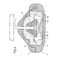
- FIG. 1 illustrates a lock according to the invention.
- the lock comprises a first member 1 in the form of a steel pin with a plastic head.
- the pin is pointed in the inlet end and comprises a turned, narrowed portion 2.
- the lock furthermore comprises a second member 5, 6 inserted in a marker for a burglar alarm on an article for sale.
- the marker is preferably made of plastics in two portions 3, 4 with 3 cavity receiving the second member 5, 6.
- the two portions 3, 4 of the marker are assembled, for instance by nlstrasonic welding, into an inseparable unit.
- the marker may be cast or pressed about the second member of the lock.
- the second member of the lock comprises two portions 5, 6 preferably made of plastics.
- a movable member 8 is positioned in this cavity.
- This movable member is a disc 9 with a pressed projection or flap 10 bent at its upper end to form a barb which can be directed towards the first member.
- the disc 9 is made of a hardened and magnetizable steel.
- the lower portion 6 of the second member is shaped during the casting with a pressed flap 11 forming a spring in the bottom of the lock.
- the spring presses the movable disc 9 upwards.
- the cavity 7 is greatest in the lower portion 6 of the second member, where both the loose, movable disc 9 and the spring 11 can be positioned.
- the cavity is so high that the disc 9 with the projection 10 can be pressed a substantial distance downwards through a suitably strong downward influence, said distance almost corresponding to half the length of the upward projection 10.
- the bottom of the cavity is insignificantly greater than the disc.
- a displacement of the third member along the sliding surface on the projection 10 implies that the disc is carried into the bottom of the lock.
- the side surface 12 of the lower portion of the second member facing the cavity .s in the illustrated embodiment provided with the same inclination as the upward projection of the :hird member.
- the disc 9 Ls of such an extent that it almost touches the above side surface.
- the uppermost portion of the cavity 7 can receive the upward projection 8 of the third member and comprises an inclined, planar or conical wall so that the cavity 7 is pointed upwards.
- the projection 10 may comprise a planar side or a curved surface such as for instance a circular, cylindrical or conical surface, and this surface is tangent to the inner wall of the upper portion of the second member.
- This inner wall may be an inclined planar wall, but it may also be provided with a curvature. It is essential that the curvature allows the two surfaces to slide against one another in order to release the first member.
- the steel pin 1 of the first member is stuck through the article, e.g. in a sewing or a seam in a garment and pressed into an opening in the uppermost portion of the second member and further into the cavity downwards and past the projection 10.
- the disc 9 with the projection 10 is pressed a short distance downwards against the force of the spring 11.
- the projection 10 fastens fixedly to the pin 1 of the first member, the pin thereby being retained. Attempts of pulling out the first member 1 imply that the pin transfers the movement to the projection 10 and the disc 9.
- the inclined surface of the projection 10 and the corresponding surface on the upper portion 5 of the second member now imply that the projection is pressed even more firmly onto the pin D f the first member and the cavity restricts the movement of the disc 9 and the projection upwards and thereby the movement of the first member.
- the second member may be reinforced by an extra hard wall 15, e.g. of light metal. In this manner this wall is prevented from giving in to the pressure that it can be subjected to when it is tried to wriggle the first member so as to tear it off.
- the pin or the rod 1 of the first member may be a completely smooth rod, but it is preferably provided with circumferential grooves or narrowings engaging the projection 10 of the third member.
- the lock is released by the third member, i.e. the disc 9 with the projection 10, being pressed or pulled downwards against the force of the spring 11.
- This procedure can be carried out by positioning the marker over a magnet, the magnetic field of which pulls down the steel disc 9.
- One or optionally several compound cobalt magnets may be used as magnet.
- the lock may be opened by inserting a needle or a U-shaped hoop downwards into one or two openings provided for this purpose in the upper portions 3, 5 in such a manner that the disc 9 can be pressed downwards as indicated in Figure 3.
- Such openings should be shaped as discrete as possible and for instance be covered by a mark as an insurance against burglary.
- FIG. 4 illustrates a second embodiment according to the invention.
- the same reference numerals have been used in the previous Figures.
- the movable member is shaped as a two-piece or truncated cone 8a, 8b, and on the inner side of each half opposing jaws 13 are provided.
- the Figure illustrates three pairs of jaws, but this number may, of course, vary.
- the inclined surface of the cone may slide on corresponding inclined surfaces 14 on the inner side of the cavity in the upper portion 5 of the second member.
- the cone is supported by two springs 11, lla in the form of cast upward plastic "flaps".
- One of the springs lla is fork-shaped and positioned symmetrically on each side about the spring 11.
- a helical spring may be used.
- the locking effect corresponds completely to the effect described in the first example.
- the two cone halves follow said pin a short distance and fasten additionally thereon and thereby retain the pin.
- the cone angle may be varied in response to the materials
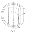
- the resilient flap 11 has been replaced by a substantially U-shaped tongue 19 communicating with the member 6 in two points 17.
- This tongue presses the disc 9 with the projection 10 upwards in the same manner as the flap 11.
- the disc 9 cannot tilt transversely to the longitudinal axis of the U.
- the U-shaped tongue cannot be hit and damaged by a steel pin 1.
Landscapes
- Burglar Alarm Systems (AREA)
- Adornments (AREA)
- Financial Or Insurance-Related Operations Such As Payment And Settlement (AREA)
- Coloring (AREA)
- Credit Cards Or The Like (AREA)
- Gloves (AREA)
- Treatment Of Fiber Materials (AREA)
- Slide Fasteners, Snap Fasteners, And Hook Fasteners (AREA)
- Lock And Its Accessories (AREA)
- Pharmaceuticals Containing Other Organic And Inorganic Compounds (AREA)
- Hydrogenated Pyridines (AREA)
Priority Applications (1)
| Application Number | Priority Date | Filing Date | Title |
|---|---|---|---|
| AT84113110T ATE36025T1 (de) | 1983-11-04 | 1984-10-31 | Schloss zur sicherung eines zeichens insbesondere an einem textilartikel. |
Applications Claiming Priority (2)
| Application Number | Priority Date | Filing Date | Title |
|---|---|---|---|
| DK5064/83 | 1983-11-04 | ||
| DK506483A DK149540C (da) | 1983-11-04 | 1983-11-04 | Laas til en tyverisikringsmarkaer |
Publications (2)
| Publication Number | Publication Date |
|---|---|
| EP0142748A1 true EP0142748A1 (de) | 1985-05-29 |
| EP0142748B1 EP0142748B1 (de) | 1988-07-27 |
Family
ID=8139142
Family Applications (1)
| Application Number | Title | Priority Date | Filing Date |
|---|---|---|---|
| EP84113110A Expired EP0142748B1 (de) | 1983-11-04 | 1984-10-31 | Schloss zur Sicherung eines Zeichens insbesondere an einem Textilartikel |
Country Status (4)
| Country | Link |
|---|---|
| EP (1) | EP0142748B1 (de) |
| AT (1) | ATE36025T1 (de) |
| DE (1) | DE3472993D1 (de) |
| DK (1) | DK149540C (de) |
Cited By (15)
| Publication number | Priority date | Publication date | Assignee | Title |
|---|---|---|---|---|
| EP0213375A2 (de) * | 1985-09-03 | 1987-03-11 | Identitech Corporation | Sicherungsklammer für die Diebstahlsicherung |
| EP0308810A2 (de) * | 1987-09-22 | 1989-03-29 | Actron Entwicklungs AG | Sicherheitsbehälter für wertvolle Gegenstände, wie CD, Platten oder Bänder sowie Verriegelungsmittel für solche Behälter |
| EP1441093A2 (de) * | 2000-07-31 | 2004-07-28 | Autronic Plastics, Inc. | Behälter mit inwendigem Schloss |
| WO2006055774A1 (en) * | 2004-11-17 | 2006-05-26 | Sensormatic Electronics Corporation | Magnetically releasable electronic article surveillance tag |
| EP1780356A1 (de) * | 2000-07-31 | 2007-05-02 | Autronic Plastics, Inc. | Behälter mit inwendigem Schloss |
| WO2008027289A2 (en) * | 2006-08-25 | 2008-03-06 | Sensormatic Electronics Corporation | Magnetically releasable electronic article surveillance tag |
| US7610782B2 (en) | 2003-02-07 | 2009-11-03 | Viva Onetime Limited | Lockable container having an integral and internal locking mechanism and methods of use |
| EP1669528A3 (de) * | 2004-12-09 | 2009-12-02 | Johan Skjellerup | Sicherheitssystem zur Vorbeugung von unerlaubtes Entfernen von Waren |
| US7750806B1 (en) | 2007-08-08 | 2010-07-06 | Johan Skjellerup | Magnetic security tag assembly |
| US8223022B2 (en) | 2004-12-09 | 2012-07-17 | Johan Skjellerup | Security tag assembly |
| US8590348B1 (en) | 2011-10-31 | 2013-11-26 | Braebum Asset Holdings, LLC. | Security tag assembly |
| US8590349B2 (en) | 2012-03-20 | 2013-11-26 | Braebum Asset Holdings, LLC. | Security tag assembly |
| AU2013213748B2 (en) * | 2006-08-25 | 2017-03-02 | Sensormatic Electronics Llc | Magnetically releasable electronic article surveillance tag |
| US10096217B2 (en) | 2016-05-11 | 2018-10-09 | Braeburn Asset Holdings, Llc | Security system and security tag assembly |
| CN110374407A (zh) * | 2019-08-20 | 2019-10-25 | 广州维琼兰科技有限公司 | 一种新型防盗标签 |
Families Citing this family (6)
| Publication number | Priority date | Publication date | Assignee | Title |
|---|---|---|---|---|
| DE3518029C2 (de) * | 1985-05-20 | 1995-01-19 | Minnesota Mining & Mfg | Diebstahlsicherung zur Einschränkung der unbefugten Entfernung von Datenträgern, insbesondere von Kompakt-Schallplatten, aus einem Gehäuse |
| DK155388C (da) * | 1986-07-08 | 1989-10-23 | Palle Pedersen | Laas |
| FR2608564B1 (fr) * | 1986-12-23 | 1990-02-16 | Velfor Plast | Emballage de produits sous coque plastique inviolable, et notamment pour disques d'enregistrements musicaux, disquettes pour informatique |
| US4987754A (en) * | 1990-01-12 | 1991-01-29 | Knogo Corporation | Magnetically releasable target lock |
| DK167465B1 (da) * | 1990-05-03 | 1993-11-01 | Actron Entwicklungs Ag | Laas til en tyverisikringsmarkoer |
| US8054194B2 (en) | 2003-02-10 | 2011-11-08 | Autronic Plastics, Inc. | System and method for verifying a security status of a lockable container |
Citations (6)
| Publication number | Priority date | Publication date | Assignee | Title |
|---|---|---|---|---|
| US3953990A (en) * | 1970-12-04 | 1976-05-04 | Nagel Alice R | Locking device |
| US4069919A (en) * | 1976-10-08 | 1978-01-24 | Fernbaugh Francis W | Security system for merchandise display |
| US4088228A (en) * | 1975-12-22 | 1978-05-09 | Ingemar Schwalbe | Clothes stand |
| GB2021675A (en) * | 1978-04-17 | 1979-12-05 | Todd J | Device for locking an article on a structure |
| US4305266A (en) * | 1979-12-21 | 1981-12-15 | Lockwood Robert G | Locking apparatus for portable devices |
| US4311883A (en) * | 1980-03-10 | 1982-01-19 | Kidney Susan L | Modular telephone jack lock |
Family Cites Families (1)
| Publication number | Priority date | Publication date | Assignee | Title |
|---|---|---|---|---|
| US3858280A (en) * | 1972-11-17 | 1975-01-07 | I D Engineering Inc | Fastening clip |
-
1983
- 1983-11-04 DK DK506483A patent/DK149540C/da not_active IP Right Cessation
-
1984
- 1984-10-31 EP EP84113110A patent/EP0142748B1/de not_active Expired
- 1984-10-31 DE DE8484113110T patent/DE3472993D1/de not_active Expired
- 1984-10-31 AT AT84113110T patent/ATE36025T1/de not_active IP Right Cessation
Patent Citations (6)
| Publication number | Priority date | Publication date | Assignee | Title |
|---|---|---|---|---|
| US3953990A (en) * | 1970-12-04 | 1976-05-04 | Nagel Alice R | Locking device |
| US4088228A (en) * | 1975-12-22 | 1978-05-09 | Ingemar Schwalbe | Clothes stand |
| US4069919A (en) * | 1976-10-08 | 1978-01-24 | Fernbaugh Francis W | Security system for merchandise display |
| GB2021675A (en) * | 1978-04-17 | 1979-12-05 | Todd J | Device for locking an article on a structure |
| US4305266A (en) * | 1979-12-21 | 1981-12-15 | Lockwood Robert G | Locking apparatus for portable devices |
| US4311883A (en) * | 1980-03-10 | 1982-01-19 | Kidney Susan L | Modular telephone jack lock |
Cited By (24)
| Publication number | Priority date | Publication date | Assignee | Title |
|---|---|---|---|---|
| EP0213375A2 (de) * | 1985-09-03 | 1987-03-11 | Identitech Corporation | Sicherungsklammer für die Diebstahlsicherung |
| EP0213375A3 (de) * | 1985-09-03 | 1988-02-03 | Identitech Corporation | Sicherungsklammer für die Diebstahlsicherung |
| EP0308810A2 (de) * | 1987-09-22 | 1989-03-29 | Actron Entwicklungs AG | Sicherheitsbehälter für wertvolle Gegenstände, wie CD, Platten oder Bänder sowie Verriegelungsmittel für solche Behälter |
| EP0308810A3 (de) * | 1987-09-22 | 1990-03-07 | Actron Entwicklungs AG | Sicherheitsbehälter für wertvolle Gegenstände, wie CD, Platten oder Bänder sowie Verriegelungsmittel für solche Behälter |
| EP1441093B1 (de) * | 2000-07-31 | 2007-02-07 | Autronic Plastics, Inc. | Behälter mit inwendigem Schloss |
| EP1780356A1 (de) * | 2000-07-31 | 2007-05-02 | Autronic Plastics, Inc. | Behälter mit inwendigem Schloss |
| EP1441093A2 (de) * | 2000-07-31 | 2004-07-28 | Autronic Plastics, Inc. | Behälter mit inwendigem Schloss |
| US7610782B2 (en) | 2003-02-07 | 2009-11-03 | Viva Onetime Limited | Lockable container having an integral and internal locking mechanism and methods of use |
| WO2006055774A1 (en) * | 2004-11-17 | 2006-05-26 | Sensormatic Electronics Corporation | Magnetically releasable electronic article surveillance tag |
| US7724146B2 (en) | 2004-11-17 | 2010-05-25 | Sensormatic Electronics, LLC | Magnetically releasable electronic article surveillance tag |
| AU2005306498B2 (en) * | 2004-11-17 | 2010-10-14 | Sensormatic Electronics Llc | Magnetically releasable electronic article surveillance tag |
| US8223022B2 (en) | 2004-12-09 | 2012-07-17 | Johan Skjellerup | Security tag assembly |
| EP1669528A3 (de) * | 2004-12-09 | 2009-12-02 | Johan Skjellerup | Sicherheitssystem zur Vorbeugung von unerlaubtes Entfernen von Waren |
| JP2010501958A (ja) * | 2006-08-25 | 2010-01-21 | センサーマティック・エレクトロニクス・コーポレーション | セキュリティタグ |
| WO2008027289A3 (en) * | 2006-08-25 | 2008-04-17 | Sensormatic Electronics Corp | Magnetically releasable electronic article surveillance tag |
| WO2008027289A2 (en) * | 2006-08-25 | 2008-03-06 | Sensormatic Electronics Corporation | Magnetically releasable electronic article surveillance tag |
| AU2013213748B2 (en) * | 2006-08-25 | 2017-03-02 | Sensormatic Electronics Llc | Magnetically releasable electronic article surveillance tag |
| US7750806B1 (en) | 2007-08-08 | 2010-07-06 | Johan Skjellerup | Magnetic security tag assembly |
| US8590348B1 (en) | 2011-10-31 | 2013-11-26 | Braebum Asset Holdings, LLC. | Security tag assembly |
| US8590349B2 (en) | 2012-03-20 | 2013-11-26 | Braebum Asset Holdings, LLC. | Security tag assembly |
| US10096217B2 (en) | 2016-05-11 | 2018-10-09 | Braeburn Asset Holdings, Llc | Security system and security tag assembly |
| US10332372B2 (en) | 2016-05-11 | 2019-06-25 | Braeburn Asset Holdings, Llc | Security system and security tag assembly |
| CN110374407A (zh) * | 2019-08-20 | 2019-10-25 | 广州维琼兰科技有限公司 | 一种新型防盗标签 |
| CN110374407B (zh) * | 2019-08-20 | 2024-04-26 | 广州维琼兰科技有限公司 | 一种防盗标签 |
Also Published As
| Publication number | Publication date |
|---|---|
| EP0142748B1 (de) | 1988-07-27 |
| DE3472993D1 (en) | 1988-09-01 |
| ATE36025T1 (de) | 1988-08-15 |
| DK149540B (da) | 1986-07-14 |
| DK506483D0 (da) | 1983-11-04 |
| DK506483A (da) | 1985-05-05 |
| DK149540C (da) | 1987-03-09 |
Similar Documents
| Publication | Publication Date | Title |
|---|---|---|
| US4745664A (en) | Lock for securing a mark especially onto a textile article | |
| EP0142748A1 (de) | Schloss zur Sicherung eines Zeichens insbesondere an einem Textilartikel | |
| US4987754A (en) | Magnetically releasable target lock | |
| EP0004068B1 (de) | Wiederverwendbare Befestigungsvorrichtung für eine Überwachungsbetätigungsvorrichtung | |
| EP1505551B1 (de) | Hartes Sichereitsetikett und Entfernungsvorrichtung | |
| EP0021849A1 (de) | Wiederverwendbare, auslösefähige Befestigung | |
| US3974581A (en) | Anti-theft fastening device and tool for releasing same | |
| AU2001253149B2 (en) | One part theft deterrent device | |
| US7190272B2 (en) | EAS tag with ball clutch | |
| US4685234A (en) | Surveillance marker clip assembly | |
| US4000543A (en) | Monitor actuating device and reusable fastener therefor | |
| US4104622A (en) | Monitor actuating device and reusable fastener therefor | |
| EP0132531B1 (de) | Befestigung für Diebstahlentdeckungsscheibe | |
| AU2001253149A1 (en) | One part theft deterrent device | |
| AU1262502A (en) | Annealed amorphous alloys for magneto-acoustic markers | |
| US4483550A (en) | Trailer hitch pin | |
| US6243922B1 (en) | Detachable clasping fastener | |
| US2633317A (en) | Golf bag support | |
| CN86108815A (zh) | 磁性紧固件 | |
| EP0092408A2 (de) | Ohrmarke und Zange dafür | |
| CA2295258C (en) | Tang break-off tool | |
| GB2137861A (en) | Improvements in or relating to a hook | |
| JPS60500782A (ja) | 締結クリツプ | |
| US5432434A (en) | System for matching a new hole in an overlying member with an existing hole in an underlying member | |
| WO1996028988A1 (en) | Item holder |
Legal Events
| Date | Code | Title | Description |
|---|---|---|---|
| PUAI | Public reference made under article 153(3) epc to a published international application that has entered the european phase |
Free format text: ORIGINAL CODE: 0009012 |
|
| AK | Designated contracting states |
Designated state(s): AT BE CH DE FR GB IT LI NL SE |
|
| 17P | Request for examination filed |
Effective date: 19851116 |
|
| 17Q | First examination report despatched |
Effective date: 19860825 |
|
| D17Q | First examination report despatched (deleted) | ||
| RAP1 | Party data changed (applicant data changed or rights of an application transferred) |
Owner name: ANTONSON SECURITY DENMARK A/S |
|
| GRAA | (expected) grant |
Free format text: ORIGINAL CODE: 0009210 |
|
| AK | Designated contracting states |
Kind code of ref document: B1 Designated state(s): AT BE CH DE FR GB IT LI NL SE |
|
| PG25 | Lapsed in a contracting state [announced via postgrant information from national office to epo] |
Ref country code: LI Effective date: 19880727 Ref country code: IT Free format text: LAPSE BECAUSE OF FAILURE TO SUBMIT A TRANSLATION OF THE DESCRIPTION OR TO PAY THE FEE WITHIN THE PRESCRIBED TIME-LIMIT;WARNING: LAPSES OF ITALIAN PATENTS WITH EFFECTIVE DATE BEFORE 2007 MAY HAVE OCCURRED AT ANY TIME BEFORE 2007. THE CORRECT EFFECTIVE DATE MAY BE DIFFERENT FROM THE ONE RECORDED. Effective date: 19880727 Ref country code: CH Effective date: 19880727 Ref country code: AT Effective date: 19880727 |
|
| REF | Corresponds to: |
Ref document number: 36025 Country of ref document: AT Date of ref document: 19880815 Kind code of ref document: T |
|
| REF | Corresponds to: |
Ref document number: 3472993 Country of ref document: DE Date of ref document: 19880901 |
|
| ET | Fr: translation filed | ||
| REG | Reference to a national code |
Ref country code: CH Ref legal event code: PL |
|
| PLBE | No opposition filed within time limit |
Free format text: ORIGINAL CODE: 0009261 |
|
| STAA | Information on the status of an ep patent application or granted ep patent |
Free format text: STATUS: NO OPPOSITION FILED WITHIN TIME LIMIT |
|
| 26N | No opposition filed | ||
| PG25 | Lapsed in a contracting state [announced via postgrant information from national office to epo] |
Ref country code: SE Effective date: 19931101 |
|
| NLT1 | Nl: modifications of names registered in virtue of documents presented to the patent office pursuant to art. 16 a, paragraph 1 |
Owner name: ACTRON DENMARK A/S TE KARLSLUNDE, DENEMARKEN. |
|
| NLS | Nl: assignments of ep-patents |
Owner name: ACTRON ENTWICKLUNGS AG TE ROTKREUZ, ZWITSERLAND. |
|
| BECA | Be: change of holder's address |
Free format text: 930722 *ACTRON ENTWICKLUNGS A.G.:LETTENSTRASSE 8, CH-6343 ROTKREUZ |
|
| BECH | Be: change of holder |
Free format text: 930722 *ACTRON ENTWICKLUNGS A.G. |
|
| PGFP | Annual fee paid to national office [announced via postgrant information from national office to epo] |
Ref country code: BE Payment date: 19940927 Year of fee payment: 11 |
|
| PGFP | Annual fee paid to national office [announced via postgrant information from national office to epo] |
Ref country code: NL Payment date: 19941031 Year of fee payment: 11 |
|
| PGFP | Annual fee paid to national office [announced via postgrant information from national office to epo] |
Ref country code: SE Payment date: 19941101 Year of fee payment: 10 |
|
| EUG | Se: european patent has lapsed |
Ref document number: 84113110.5 Effective date: 19940610 |
|
| PGFP | Annual fee paid to national office [announced via postgrant information from national office to epo] |
Ref country code: FR Payment date: 19950913 Year of fee payment: 12 |
|
| PGFP | Annual fee paid to national office [announced via postgrant information from national office to epo] |
Ref country code: GB Payment date: 19950914 Year of fee payment: 12 |
|
| PGFP | Annual fee paid to national office [announced via postgrant information from national office to epo] |
Ref country code: DE Payment date: 19950920 Year of fee payment: 12 |
|
| PG25 | Lapsed in a contracting state [announced via postgrant information from national office to epo] |
Ref country code: BE Effective date: 19951031 |
|
| BERE | Be: lapsed |
Owner name: ACTRON ENTWICKLUNGS A.G. Effective date: 19951031 |
|
| PG25 | Lapsed in a contracting state [announced via postgrant information from national office to epo] |
Ref country code: NL Effective date: 19960501 |
|
| NLV4 | Nl: lapsed or anulled due to non-payment of the annual fee |
Effective date: 19960501 |
|
| PG25 | Lapsed in a contracting state [announced via postgrant information from national office to epo] |
Ref country code: GB Effective date: 19961031 |
|
| GBPC | Gb: european patent ceased through non-payment of renewal fee |
Effective date: 19961031 |
|
| PG25 | Lapsed in a contracting state [announced via postgrant information from national office to epo] |
Ref country code: FR Effective date: 19970630 |
|
| PG25 | Lapsed in a contracting state [announced via postgrant information from national office to epo] |
Ref country code: DE Effective date: 19970701 |
|
| REG | Reference to a national code |
Ref country code: FR Ref legal event code: ST |