EP0142733A2 - Ultrasonic rangefinder - Google Patents
Ultrasonic rangefinder Download PDFInfo
- Publication number
- EP0142733A2 EP0142733A2 EP19840112776 EP84112776A EP0142733A2 EP 0142733 A2 EP0142733 A2 EP 0142733A2 EP 19840112776 EP19840112776 EP 19840112776 EP 84112776 A EP84112776 A EP 84112776A EP 0142733 A2 EP0142733 A2 EP 0142733A2
- Authority
- EP
- European Patent Office
- Prior art keywords
- output
- signal
- ultrasonic
- time
- rangefinder
- Prior art date
- Legal status (The legal status is an assumption and is not a legal conclusion. Google has not performed a legal analysis and makes no representation as to the accuracy of the status listed.)
- Withdrawn
Links
Images


Classifications
-
- G—PHYSICS
- G01—MEASURING; TESTING
- G01S—RADIO DIRECTION-FINDING; RADIO NAVIGATION; DETERMINING DISTANCE OR VELOCITY BY USE OF RADIO WAVES; LOCATING OR PRESENCE-DETECTING BY USE OF THE REFLECTION OR RERADIATION OF RADIO WAVES; ANALOGOUS ARRANGEMENTS USING OTHER WAVES
- G01S7/00—Details of systems according to groups G01S13/00, G01S15/00, G01S17/00
- G01S7/52—Details of systems according to groups G01S13/00, G01S15/00, G01S17/00 of systems according to group G01S15/00
- G01S7/523—Details of pulse systems
- G01S7/526—Receivers
-
- G—PHYSICS
- G01—MEASURING; TESTING
- G01S—RADIO DIRECTION-FINDING; RADIO NAVIGATION; DETERMINING DISTANCE OR VELOCITY BY USE OF RADIO WAVES; LOCATING OR PRESENCE-DETECTING BY USE OF THE REFLECTION OR RERADIATION OF RADIO WAVES; ANALOGOUS ARRANGEMENTS USING OTHER WAVES
- G01S15/00—Systems using the reflection or reradiation of acoustic waves, e.g. sonar systems
- G01S15/02—Systems using the reflection or reradiation of acoustic waves, e.g. sonar systems using reflection of acoustic waves
- G01S15/06—Systems determining the position data of a target
- G01S15/08—Systems for measuring distance only
- G01S15/10—Systems for measuring distance only using transmission of interrupted, pulse-modulated waves
- G01S15/18—Systems for measuring distance only using transmission of interrupted, pulse-modulated waves wherein range gates are used
-
- G—PHYSICS
- G01—MEASURING; TESTING
- G01S—RADIO DIRECTION-FINDING; RADIO NAVIGATION; DETERMINING DISTANCE OR VELOCITY BY USE OF RADIO WAVES; LOCATING OR PRESENCE-DETECTING BY USE OF THE REFLECTION OR RERADIATION OF RADIO WAVES; ANALOGOUS ARRANGEMENTS USING OTHER WAVES
- G01S7/00—Details of systems according to groups G01S13/00, G01S15/00, G01S17/00
- G01S7/52—Details of systems according to groups G01S13/00, G01S15/00, G01S17/00 of systems according to group G01S15/00
- G01S7/523—Details of pulse systems
- G01S7/526—Receivers
- G01S7/527—Extracting wanted echo signals
Definitions
- This invention relates to an ultrasonic rangefinder and more paticularly to an ultrasonic rengefinder in which ultrasonic waves are transmitted toward the ground and the time necessary for the reflected wave to return is used to estimate the distance to the ground.
- Anobject of this invention is to provide an ultrasonic rangefinder in which erroneous measurement is not caused by such effects as the spurious detour signal.
- Another object of this invention is to provide an ultrasonic rangefinder in which the desired reflected wave can be reliably distinguished from the spurious signal.
- the distance calculation is based on the time from the transmission of the ultrasonic wave until the time at which the rate of change of the envelope of the waveform of the reflected wave exceeds a prescribed value.
- Fig. 1 shows an example of a conventional ultrasonic rangefinder of this type and signal waveforms at various locations in the conventional rangfinder are depicted in Figs. 2 (A) through 2 (F).
- An oscillator 1 generates a transmitted wave S l the freqauency of which matches the resonant frequency of the transmitter microphone 2 and the receiver microphone 3.
- the ultrasonic wave R 1 travels to the object of measurement 10 a distance h from the transmitter microphone 2 in a time t T .
- the ultrasonic wave R 1 which is reflected from the object of measurement 10 is received by the receiver microphone 3, converted to an electrical signal and input to the amplifier 4.
- the reflection signal S 2 which is amplified by the amplifier 4 enters the detection and smoothing circuit 5.
- the envelope signal S 3 shown in Fig. 2 (C) is obtained.
- This signal S 3 is compared with the reference voltage D generated by the reference voltage generator 7 in the comparator 6.
- the judgment signal S 4 is output.
- the envelope signal S 3 includes a part E 1 which is formed by the reflected wave R 1 (referred to below as the "reflected output E 1 "), and another part E 2 which is formed by the detour wave which enters the receiver microphone 3 directly from the transmitter microphone 2 (referred to below as the "detour output E 2 ").
- the AND circuit 9 forms the logical product of the mask signal S 5 , which is caused to rise a time t after the transmitted wave S 1 by the time delay circuit 8, and the judgment signal S 4 , and outputs said logical product as the AND output signal 8 6 .
- the number of pulses from the clock 14, which starts upon transmission of the transmitted wave S1 is output by the latch circuit 12 with the timing of the output S 6 from the AND circuit 9, that is, with the time width t.
- the time width t varies in response to the distance h since it is the arrival time of the reflected output E l .
- the distance h can be calculated from the time width t on the basis of the period of the clock 14 and the speed of sound by the calculator 15. After latching the counter 11 is reset through the time delay circuit 13.
- the speed of sound in air is given by the following formula when the air temperature is T:
- the rangefinder as shown in Fig. 3, while part of the ultrasonic wave transmitted from the transmitter microphone 2 toward the object of measurement 10 strikes the object 10 and is reflected as the ultrasonic wave R l , which enters the receiver microphone 3, part does not reach the object 10 but detours directly from the transmitter microphone 2 to the receiver microphone 3 as the detour component R 2 .
- the transmitter microphone 2 and the receiver microphone 3 are not perfectly directional so that some transmitting and receiving are done even at 90° to the intended direction of wave travel. Since the travel times of these two ultrasonic waves R l , and R 2 are different from each other, as can be easily seen from Fig. 2 the detour output E 2 due to the detour wave R 2 appears at a different time than the refelction output E 1 due to the ultrasonic wave R 1 , which is reflected from the object of measurement 10.
- the detour output E 2 since the travel path of the detour wave R 2 is always the same, the detour output E 2 always appears within a fixed time after the transmission of the transmitted wave S l . For this reason, as is shown in Fig. 4, as the distance h gradually increases, in the envelope of the signal S 3 the time until the reflection output E 1 appears gradually increases, as shown by the times t l , t 2 , and t 3 in Fig. 4 (A), (B) and (C) respectively; but the time until the detour output E 2 appears does not vary. Since this detour output E 2 is not needed for a distance measurement, it is removed by the time delay circuit 8 and the AND circuit 9, and only the rise of the reflection output E 1 is detected.
- the time delay produced by this time delay circuit 8 is nearly determined by the travel time of the ultrasonic waves, but, since the frequency of the transmitted wave S 1 is made to resonate with the transmitter microphone 2 and the receiver microphone 3 in order to increase output, the signal S 2 does not rise as sharply as the transmitted wave S l , and attenuation vibrations remain, leaving a trace.
- the magnitude of these attenuation vibrations is determined by the sharpness Q of the resonance of the transmitter microphone 2 and the receiver microphone 3 and changes very little.
- the time delay ⁇ is set to a value which leaves plenty of leeway for the detour output E 2 due to these attenuation vibrations to become much smaller than the reference voltage D.
- the Q of the transmitter microphone and the receiver microphone is set to a large value in this type of ultrasonic rangefinder, the attenuation vibration of the received signal are slso large, so that the overlap between the detour output E 2 and the reflection output E 1 becomes large and the rise of the reflection output E 1 becomes difficult to detect. Occasionally the detour output E 2 is mistaken for the reflection outpnt E l giving an erroneous distance measurement.
- Fig. 5 shows an embodiment of a rangefinder in which this invention is applied.
- the embodiment has a differentiation circuit 16 which differentiate the envlope E which is output from the detection and amplifier circuit 5 of the rangefinder shown in Fig. 1.
- the output S3, of the differentiation circuit 16 is compared with the reference voltage D from the reference voltage generator 15 in the comparator 6.
- Other circuit components are the same as in Fig. 1.
- Figs. 6 (A) through 6 (F) show the signal waveforms at various locations in the circuitry of the rangefinder shown in Figs. 5. Those signals which are the same as in Fig. 1 and Fig. 2 are shown with the same symbols.
- the signal S 3 in Fig. 6 (C) is obtained by differentiating the envelope of the signal S 3 which is output from the detector and amplifier circuit 5. This signal S 3 is compared with the reference voltage D from the reference voltage generator 15 in the comparator 6, which outputs the judgment signal S 4 shown in Fig. 6 (D). After that the judgment is performed in the same manner as in the conventional type of rangefinder shown in Fig. 1 (refere to Fig. 6 (E) and (F) ).
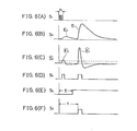
- Figs. 7 (A) through 7 (E) show signal waveforms in the existing type of rangefinder while Figs. 8 (A) through 8 (F) show signal waveforms in a rangefinder in accordance with this invention.
- the detour output E 2 arising from the detour ultrasonic wave R 2 from the transmitter microphone 2 to the receiver microphone 34 is determined by the directionality of the microphone. This directionality in turn is greatly affected by the physical shape of the microphone.
- this rangefinder is used as a vehicle height sensor, if mud gets on the microphone during operation it is essentially the same as a change in the shape of the microphone and the detour output can increase. Supposing that the detour wave R 2 increases, the detour output E 2 increases from the solid line to the dotted line in Fig. 7 (B).
- the attenuation vibrations do not appear in the differentiated output E so that there is little if any change in the time width of the judgment signal s 4 so that the output S 6 of the AND circuit 9 has the correct time width t.
- the reference voltage D can be as small as 0, in fact, this gives the least error.
- the envelope of the reflected wave is differentiated and the derivative is detected as a means of accurately detecting the reflection output, it is also possible to achieve the same objective by differentiating the differentiated output once more to obtain the second derivative and then detecting the second derivatived.
Abstract
An ultrasonicrangefinder which measures distance to the ground by transmitting ultrasonic waves toward the ground and measuring the time which elapses until the reflected wave is received is shown. In order to reliably prevent erroneous measurement due to ultrasonic waves which travel to the receiver directly without striking the ground, the distance calculation is based on the time which elapses aftertransmis- sion of the ultrasonic wave until the rate of change of the envelope of the received ultrasonic wave signal exceeds a prescribed value.
Description
- This invention relates to an ultrasonic rangefinder and more paticularly to an ultrasonic rengefinder in which ultrasonic waves are transmitted toward the ground and the time necessary for the reflected wave to return is used to estimate the distance to the ground.
- Technologies for an ultrasonic rangefinder which transmits ultrasonic waves downward from a vehicle toward the ground, receives the reflected waves from the ground, and uses the time from transmission to reception to measure the distance to the ground, and for an ultrasonic speedmeter which uses the frequency shift between the frequency of the transmitted waves and the frequency of the received reflected waves to measure the speed of the vehicle relative to the ground, are shown in the prior art, for example, Utility Model Published Application Sho 57 - No. 68575.
- In this kind of rangefinder there are at least two causes which produce spurious waves. One of them is an attenuation signal which is generated when the ultrasonic signal leaves a trace in the transmitter microphone or in the receiver microphone. The other is the signal which travels directly from the transmitter microphone to the receiver microphone. Since the latter spurious wave is always delayed by a fixed time with respect to the transmitted wave, its effect can be eliminated by determining that time and removing signals received within that time of the transmission of the transmitted wave. However, until now there has been a problem in that the attenuation signal in the transmitter microphone and the detour signal mentioned above leave traces in the receiver microphone which overlap with the desired reflected signal, causing undersirable side effects.
- Anobject of this invention is to provide an ultrasonic rangefinder in which erroneous measurement is not caused by such effects as the spurious detour signal.
- Another object of this invention is to provide an ultrasonic rangefinder in which the desired reflected wave can be reliably distinguished from the spurious signal.
- In order to accomplish the above ojbects, in this invention, in an ultrasonic rangefinder which measures the distance to the ground by transmitting ultrasonic waves toward the ground and measuring the time which elapses until the reflected waves are received, the distance calculation is based on the time from the transmission of the ultrasonic wave until the time at which the rate of change of the envelope of the waveform of the reflected wave exceeds a prescribed value.
-
- Fig. 1 is a block diagram of a conventional type of ultrasonic rangefinder.
- Figs. 2 (A) through 2 (F) show signal waveforms at various locations in the conventional ultrasonic rangefinder shown in Fig. 1.
- Fig. 3 is a view showing the detouring of ultrasonic waves.
- Figs. 4 (A) through 4 (D) are graphs showing signal wave-forms in a operation of an conventional ultrasonic rangefinder.
- Fig. 5 is a block diagram of an embodiment of an ultrasonic rangefinder in accoralance with the present invention.
- Figs. 6 (A) through 6 (F) are graphs showing signal waveforms at various locations in the ultrasonic rangefinder shown in Fig. 5.
- Figs. 7 (A) through 7 (E) are graphs showing waveforms which are used in explaining what can go wrong in an ultrasonic rangefinder.
- Figs. 8 (A) through 8 (F) are graphs showing signal wavesforms in an operation of an ultrasonic rangefinder in accordance with the invention.
- To facilitatge the understanding of the present invention, a brief reference will be made to a conventional rangefinder.
- Fig. 1 shows an example of a conventional ultrasonic rangefinder of this type and signal waveforms at various locations in the conventional rangfinder are depicted in Figs. 2 (A) through 2 (F). An
oscillator 1 generates a transmitted wave Sl the freqauency of which matches the resonant frequency of thetransmitter microphone 2 and thereceiver microphone 3. The ultrasonic wave R1 travels to the object of measurement 10 a distance h from thetransmitter microphone 2 in a time tT. The ultrasonic wave R1 which is reflected from the object ofmeasurement 10, is received by thereceiver microphone 3, converted to an electrical signal and input to the amplifier 4. The reflection signal S2 which is amplified by the amplifier 4 enters the detection andsmoothing circuit 5. Here the envelope signal S3 shown in Fig. 2 (C) is obtained. This signal S3 is compared with the reference voltage D generated by the reference voltage generator 7 in thecomparator 6. When the level of the signal S3 exceeds the reference voltage D the judgment signal S4 is output. The envelope signal S3 includes a part E1 which is formed by the reflected wave R1 (referred to below as the "reflected output E1"), and another part E2 which is formed by the detour wave which enters thereceiver microphone 3 directly from the transmitter microphone 2 (referred to below as the "detour output E2"). - Meanwhile, the AND circuit 9 forms the logical product of the mask signal S5, which is caused to rise a time t after the transmitted wave S1 by the
time delay circuit 8, and the judgment signal S4, and outputs said logical product as theAND output signal 86. The number of pulses from theclock 14, which starts upon transmission of the transmitted wave S1, is output by thelatch circuit 12 with the timing of the output S6 from the AND circuit 9, that is, with the time width t. The time width t varies in response to the distance h since it is the arrival time of the reflected output El. The distance h can be calculated from the time width t on the basis of the period of theclock 14 and the speed of sound by thecalculator 15. After latching thecounter 11 is reset through thetime delay circuit 13. The speed of sound in air is given by the following formula when the air temperature is T: - c = 331 + 0.607T (m/s)
- h = ct/2 (m)
- However, in the rangefinder, as shown in Fig. 3, while part of the ultrasonic wave transmitted from the
transmitter microphone 2 toward the object ofmeasurement 10 strikes theobject 10 and is reflected as the ultrasonic wave Rl, which enters thereceiver microphone 3, part does not reach theobject 10 but detours directly from thetransmitter microphone 2 to thereceiver microphone 3 as the detour component R2. This is because thetransmitter microphone 2 and the receiver microphone 3 are not perfectly directional so that some transmitting and receiving are done even at 90° to the intended direction of wave travel. Since the travel times of these two ultrasonic waves Rl, and R2 are different from each other, as can be easily seen from Fig. 2 the detour output E2 due to the detour wave R2 appears at a different time than the refelction output E1 due to the ultrasonic wave R1, which is reflected from the object ofmeasurement 10. - Moreover, since the travel path of the detour wave R2 is always the same, the detour output E2 always appears within a fixed time after the transmission of the transmitted wave Sl. For this reason, as is shown in Fig. 4, as the distance h gradually increases, in the envelope of the signal S3 the time until the reflection output E1 appears gradually increases, as shown by the times tl, t2, and t3 in Fig. 4 (A), (B) and (C) respectively; but the time until the detour output E2 appears does not vary. Since this detour output E2 is not needed for a distance measurement, it is removed by the
time delay circuit 8 and the AND circuit 9, and only the rise of the reflection output E1 is detected. The time delay produced by thistime delay circuit 8 is nearly determined by the travel time of the ultrasonic waves, but, since the frequency of the transmitted wave S1 is made to resonate with thetransmitter microphone 2 and thereceiver microphone 3 in order to increase output, the signal S2 does not rise as sharply as the transmitted wave Sl, and attenuation vibrations remain, leaving a trace. - The magnitude of these attenuation vibrations is determined by the sharpness Q of the resonance of the
transmitter microphone 2 and thereceiver microphone 3 and changes very little. For this reeason the time delay τ is set to a value which leaves plenty of leeway for the detour output E2 due to these attenuation vibrations to become much smaller than the reference voltage D. However, since the Q of the transmitter microphone and the receiver microphone is set to a large value in this type of ultrasonic rangefinder, the attenuation vibration of the received signal are slso large, so that the overlap between the detour output E2 and the reflection output E1 becomes large and the rise of the reflection output E1 becomes difficult to detect. Occasionally the detour output E2 is mistaken for the reflection outpnt El giving an erroneous distance measurement. - Now the present invention will be described with reference to the drawings.
- Fig. 5 shows an embodiment of a rangefinder in which this invention is applied. The embodiment has a
differentiation circuit 16 which differentiate the envlope E which is output from the detection andamplifier circuit 5 of the rangefinder shown in Fig. 1. The output S3, of thedifferentiation circuit 16 is compared with the reference voltage D from thereference voltage generator 15 in thecomparator 6. Other circuit components are the same as in Fig. 1. - Figs. 6 (A) through 6 (F) show the signal waveforms at various locations in the circuitry of the rangefinder shown in Figs. 5. Those signals which are the same as in Fig. 1 and Fig. 2 are shown with the same symbols. The signal S3 in Fig. 6 (C) is obtained by differentiating the envelope of the signal S3 which is output from the detector and
amplifier circuit 5. This signal S3 is compared with the reference voltage D from thereference voltage generator 15 in thecomparator 6, which outputs the judgment signal S4 shown in Fig. 6 (D). After that the judgment is performed in the same manner as in the conventional type of rangefinder shown in Fig. 1 (refere to Fig. 6 (E) and (F) ). - This solves the problem of erroneous measurement due to the detour output E2. How it does so will now be explained with reference to Figs. 7 and Figs. 8. Figs. 7 (A) through 7 (E) show signal waveforms in the existing type of rangefinder while Figs. 8 (A) through 8 (F) show signal waveforms in a rangefinder in accordance with this invention.
- The detour output E2 arising from the detour ultrasonic wave R2 from the
transmitter microphone 2 to the receiver microphone 34 is determined by the directionality of the microphone. This directionality in turn is greatly affected by the physical shape of the microphone. When this rangefinder is used as a vehicle height sensor, if mud gets on the microphone during operation it is essentially the same as a change in the shape of the microphone and the detour output can increase. Supposing that the detour wave R2 increases, the detour output E2 increases from the solid line to the dotted line in Fig. 7 (B). At this time the attenuation vibrations of the microphone are large, so that the time interval during which the detour output E2 is larger than the reference voltage D becomes longer, and, as a result, the judgment signal S3 becomes longer, as shown by the dotted line in Fig. 7 (C). This causes the judgment signal S4 to persist beyond the time delay τ so that the output of the AND circuit 9 does not have the normal time delay t but rather has the same time width as the time delay τ of the mask signal S5, causing erroneous distance measurement. - In contrast, in the present invention, as shown in A Figs. 8, even if the detour output E2 increases causing the attenuation vibrations to increase, the attenuation vibrations do not appear in the differentiated output E so that there is little if any change in the time width of the judgment signal s4 so that the output S6 of the AND circuit 9 has the correct time width t. The reference voltage D can be as small as 0, in fact, this gives the least error.
- In the embodiment described above the envelope of the reflected wave is differentiated and the derivative is detected as a means of accurately detecting the reflection output, it is also possible to achieve the same objective by differentiating the differentiated output once more to obtain the second derivative and then detecting the second derivatived.
- It should be understood, of course, that the foregoing relates only to preferred embodiments of the present invention and that numerous modifications or alterations may be made therein without departing from the spirit and scope of the invention as set forth in the appended claims.
Claims (7)
1. A ultrasonic rangefinder comprising:
an oscilator (1) generating a series of pulse signals (S1);
a transmitter microphone (2) which emits ultrasonic pulses toward a target object (10) on the basis of the pulse signals transmitted from said oscillator (1);
a receiver microphone (3) which receives ultrasonic pulses reflected from said target object (10);
a means (14) for differentiating by time the envelope of the output signals (S2) of said receiver microphone (3)
a means for detecting (6,7) the rise of the signal corresponding to the refrected pulse on the basis of the A output signal (S3) of said differentiating means (16);
a means for calculating a distance between said rangefinder and the object (10) on the basis of a delay time of the rise detected by said detecting means in relation to the pulse signal (S1) from said oscillator (1)
2. An ultrasonic rangefinder of claim l.further comprising a means (8, 9) for eliminating the signals corresponding to the output (52) from said receiver microphone (3) during a prescribed period (c) after an emission of pulse from said transmitter microphone (3).
3. An ultrasonic rangefinder of claim2, wherein said detecting means comprises:
a reference voltage generator (7) and
a comparator (6) receiving the output signal from said differentiating means (16) and the output from said generator and allowing the output signal from said differentiating means to enter said calculating means.
4. An ultrasonic rangefinder of claim 3 wherein, said eliminating means comprises:
a time delay circuit (8) receiving the pulse singnal (S1) from said oscillator (1) and outputting a mask signal (S5) which starts with the delay time (τ) of said prescribed period after the pulse signal (S1) from said oscillator (1)
an AND circuit receiving the output of said delay circuit (8) and the output of said comparator (6)
-5. An ultrasonic rangefinder of claim 4 further comprising:
a clock (14);
a counter (11) which starts its counting when it receives the pulse signal (S1) from said oscillator (1);
a latch circuit (12) which receives the output of said counter (11) and the output (S6) of said AND circuit (9) and outputs the output of said counter when the output (S6) of said AND circuit (9) is received;
a time delay circuit which allows the output (S6) of said AND circuit (9) to enter said counter (11) with delay time to reset said counter.
6. An ultrasonic rangefinder of claim 1 wherein; said envelope is differentiated for one time
7. An ultrasonic rangefinder of claim 1 wherein; said envelope is differentiated for multi-times
Applications Claiming Priority (2)
| Application Number | Priority Date | Filing Date | Title |
|---|---|---|---|
| JP197655/83 | 1983-10-24 | ||
| JP19765583A JPS6089783A (en) | 1983-10-24 | 1983-10-24 | Ultrasonic distance detector |
Publications (1)
| Publication Number | Publication Date |
|---|---|
| EP0142733A2 true EP0142733A2 (en) | 1985-05-29 |
Family
ID=16378109
Family Applications (1)
| Application Number | Title | Priority Date | Filing Date |
|---|---|---|---|
| EP19840112776 Withdrawn EP0142733A2 (en) | 1983-10-24 | 1984-10-23 | Ultrasonic rangefinder |
Country Status (2)
| Country | Link |
|---|---|
| EP (1) | EP0142733A2 (en) |
| JP (1) | JPS6089783A (en) |
Cited By (9)
| Publication number | Priority date | Publication date | Assignee | Title |
|---|---|---|---|---|
| US4677599A (en) * | 1984-06-20 | 1987-06-30 | Nissan Motor Company, Limited | Ultra-sonic distance measuring apparatus and method |
| GB2207757A (en) * | 1987-08-07 | 1989-02-08 | Sonin Inc | Ultrasonic rangefinder |
| EP0336057A1 (en) * | 1988-03-28 | 1989-10-11 | Hewlett-Packard Company | Hardware correction scheme for inter frame image jitter in a scanning probe ultrasound imaging system |
| EP1296159A3 (en) * | 2001-09-19 | 2004-01-14 | Robert Bosch Gmbh | Method for measuring distance |
| US7068214B2 (en) * | 2003-02-19 | 2006-06-27 | Fujitsu Ten Limited | Radar |
| EP2192419A3 (en) * | 2008-11-26 | 2012-07-25 | Robert Bosch GmbH | Method for dynamic calculation of noise levels |
| DE102013226085B3 (en) * | 2013-12-16 | 2015-03-26 | Elmos Semiconductor Aktiengesellschaft | Method for processing an echo signal of an ultrasonic transducer |
| CN106199614A (en) * | 2015-05-29 | 2016-12-07 | 罗伯特·博世有限公司 | For the method and apparatus detecting the object in vehicle-periphery |
| CN111610530A (en) * | 2019-02-22 | 2020-09-01 | 半导体元件工业有限责任公司 | Ultrasonic sensor with edge-based echo detection |
Families Citing this family (5)
| Publication number | Priority date | Publication date | Assignee | Title |
|---|---|---|---|---|
| US5159835A (en) * | 1986-10-29 | 1992-11-03 | Westinghouse Electric Corp. | Check valve testing system |
| US4977778A (en) * | 1986-10-29 | 1990-12-18 | Movats Incorporated | Check valve testing system |
| US5154080A (en) * | 1986-10-29 | 1992-10-13 | Westinghouse Electric Corp. | Integrated check valve testing system |
| JP2958362B2 (en) * | 1990-04-28 | 1999-10-06 | 孝次 時松 | Measurement, analysis and judgment method of ground structure |
| JP3456924B2 (en) * | 1999-07-01 | 2003-10-14 | アオイ電子株式会社 | Microphone device |
Family Cites Families (1)
| Publication number | Priority date | Publication date | Assignee | Title |
|---|---|---|---|---|
| DE2930046C2 (en) * | 1979-07-24 | 1982-02-04 | Alcan Aluminiumwerke GmbH, 3400 Göttingen | Exhaust silencers for internal combustion engines |
-
1983
- 1983-10-24 JP JP19765583A patent/JPS6089783A/en active Pending
-
1984
- 1984-10-23 EP EP19840112776 patent/EP0142733A2/en not_active Withdrawn
Cited By (12)
| Publication number | Priority date | Publication date | Assignee | Title |
|---|---|---|---|---|
| US4677599A (en) * | 1984-06-20 | 1987-06-30 | Nissan Motor Company, Limited | Ultra-sonic distance measuring apparatus and method |
| GB2207757A (en) * | 1987-08-07 | 1989-02-08 | Sonin Inc | Ultrasonic rangefinder |
| GB2207757B (en) * | 1987-08-07 | 1991-09-04 | Sonin Inc | Apparatus for measuring distances |
| EP0336057A1 (en) * | 1988-03-28 | 1989-10-11 | Hewlett-Packard Company | Hardware correction scheme for inter frame image jitter in a scanning probe ultrasound imaging system |
| EP1296159A3 (en) * | 2001-09-19 | 2004-01-14 | Robert Bosch Gmbh | Method for measuring distance |
| US7068214B2 (en) * | 2003-02-19 | 2006-06-27 | Fujitsu Ten Limited | Radar |
| EP2192419A3 (en) * | 2008-11-26 | 2012-07-25 | Robert Bosch GmbH | Method for dynamic calculation of noise levels |
| DE102013226085B3 (en) * | 2013-12-16 | 2015-03-26 | Elmos Semiconductor Aktiengesellschaft | Method for processing an echo signal of an ultrasonic transducer |
| WO2015091023A1 (en) | 2013-12-16 | 2015-06-25 | Elmos Semiconductor Aktiengesellschaft | Method for processing an echo signal of an ultrasonic transducer |
| CN106199614A (en) * | 2015-05-29 | 2016-12-07 | 罗伯特·博世有限公司 | For the method and apparatus detecting the object in vehicle-periphery |
| CN106199614B (en) * | 2015-05-29 | 2021-08-31 | 罗伯特·博世有限公司 | Method and device for detecting objects in the surroundings of a vehicle |
| CN111610530A (en) * | 2019-02-22 | 2020-09-01 | 半导体元件工业有限责任公司 | Ultrasonic sensor with edge-based echo detection |
Also Published As
| Publication number | Publication date |
|---|---|
| JPS6089783A (en) | 1985-05-20 |
Similar Documents
| Publication | Publication Date | Title |
|---|---|---|
| US5796009A (en) | Method for measuring in a fluid with the aid of sing-around technique | |
| US4933915A (en) | Method of indicating the time of an acoustic pulse and a device for carrying out the method | |
| EP0142733A2 (en) | Ultrasonic rangefinder | |
| US4606015A (en) | Method and apparatus for detecting position of object with ultrasonic wave | |
| JPH06148003A (en) | Ultrasonic temperature measuring equipment | |
| JP2859514B2 (en) | Doppler shift correction pulse type fishing net depth gauge | |
| US4567766A (en) | Piezoelectric ultrasonic apparatus and method for determining the distance from a predetermined point to a target | |
| US4719605A (en) | Self-calibrating ultrasonic range finder | |
| EP0981201B1 (en) | Zero crossing detector and method of determining a zero crossing point | |
| EP0272942B1 (en) | Speed measurement device | |
| JPH08136643A (en) | Ultrasonic distance measuring instrument | |
| JPH08136321A (en) | Ultrasonic distance measuring instrument | |
| RU2195635C1 (en) | Method of measurement of level of liquid and loose media | |
| SU987393A1 (en) | Ultrasonic flow speed meter | |
| RU1820230C (en) | Device for measuring speed of propagation of ultrasonic oscillations | |
| JPH0534193A (en) | Ultrasonic transmitter-receiver | |
| JPS59218973A (en) | On-vehicle obstacle detector | |
| JPH10123238A (en) | Distance measuring device | |
| JPS6394184A (en) | Ultrasonic wave displacement detecting device | |
| JPS61241685A (en) | Ultrasonic range finder | |
| JPH0712927A (en) | Ultrasonic object detecting device | |
| JPH11326512A (en) | Ultrasonic range finder | |
| JPH053526B2 (en) | ||
| JPH0882673A (en) | Ultrasonic distance-measuring apparatus | |
| JPS6040980A (en) | Doppler radar speedometer |
Legal Events
| Date | Code | Title | Description |
|---|---|---|---|
| PUAI | Public reference made under article 153(3) epc to a published international application that has entered the european phase |
Free format text: ORIGINAL CODE: 0009012 |
|
| AK | Designated contracting states |
Designated state(s): DE FR GB |
|
| RAP1 | Party data changed (applicant data changed or rights of an application transferred) |
Owner name: NISSAN MOTOR CO., LTD. |
|
| STAA | Information on the status of an ep patent application or granted ep patent |
Free format text: STATUS: THE APPLICATION HAS BEEN WITHDRAWN |
|
| 18W | Application withdrawn |
Withdrawal date: 19860812 |
|
| RIN1 | Information on inventor provided before grant (corrected) |
Inventor name: KOBAYASHI, HIROSHI Inventor name: TAKEUCHI, KIYOSHI Inventor name: OBAYASHI, HIROAKI |