EP0142101B1 - Automotive engine control system capable of detecting specific engine operating conditions and projecting subsequent engine operating patterns - Google Patents
Automotive engine control system capable of detecting specific engine operating conditions and projecting subsequent engine operating patterns Download PDFInfo
- Publication number
- EP0142101B1 EP0142101B1 EP84113075A EP84113075A EP0142101B1 EP 0142101 B1 EP0142101 B1 EP 0142101B1 EP 84113075 A EP84113075 A EP 84113075A EP 84113075 A EP84113075 A EP 84113075A EP 0142101 B1 EP0142101 B1 EP 0142101B1
- Authority
- EP
- European Patent Office
- Prior art keywords
- engine
- data
- pattern data
- actual
- operation pattern
- Prior art date
- Legal status (The legal status is an assumption and is not a legal conclusion. Google has not performed a legal analysis and makes no representation as to the accuracy of the status listed.)
- Expired - Lifetime
Links
Images


Classifications
-
- F—MECHANICAL ENGINEERING; LIGHTING; HEATING; WEAPONS; BLASTING
- F02—COMBUSTION ENGINES; HOT-GAS OR COMBUSTION-PRODUCT ENGINE PLANTS
- F02D—CONTROLLING COMBUSTION ENGINES
- F02D41/00—Electrical control of supply of combustible mixture or its constituents
- F02D41/24—Electrical control of supply of combustible mixture or its constituents characterised by the use of digital means
- F02D41/2406—Electrical control of supply of combustible mixture or its constituents characterised by the use of digital means using essentially read only memories
- F02D41/2496—Electrical control of supply of combustible mixture or its constituents characterised by the use of digital means using essentially read only memories the memory being part of a closed loop
-
- F—MECHANICAL ENGINEERING; LIGHTING; HEATING; WEAPONS; BLASTING
- F02—COMBUSTION ENGINES; HOT-GAS OR COMBUSTION-PRODUCT ENGINE PLANTS
- F02D—CONTROLLING COMBUSTION ENGINES
- F02D41/00—Electrical control of supply of combustible mixture or its constituents
- F02D41/02—Circuit arrangements for generating control signals
- F02D41/04—Introducing corrections for particular operating conditions
Definitions
- the invention relates to an engine control system for an internal combustion engine.
- a stored look-up table is generated to govern the amount of change in the auxiliary air supply passage upon detection of a transient. After a transient is detected, the amount of air flow in the auxiliary air supply passage is altered as a function of the look-up table. As the transient passes, the air flow is adjusted in the auxiliary air supply passage to a value suitable for compensating for the next predicted transient.
- the system includes adaptively updating the look-up table to take into account engine operating conditions. The use of air control is advantageous compared to the control of the fuel flow because of increased speed of response offered by the auxiliary air supply passage.
- the object of the present invention is an improved engine control system having a fast response, and avoiding time lapse between measuring of actual engine parameters and a desired operation condition by predicting forthcoming engine operation conditions under consideration of the measured actual engine parameters.
- the engine operation model pattern is a model of variation of parameters showing the probability of causing specific engine driving conditions whereby a predicted control of the engine with foresight of following engine behaviour or engine condition is performed.
- the control system adjusts the control procedures in response to preselected engine operating conditions in accordance with a projected engine operation pattern derived from the pre-recorded engine operation pattern data and the detected specific engine operating condition.
- the engine operation pattern data may be repeatedly updated and/or accumulated during engine operation and may be held in a memory of the control system even after the engine is turned off.
- the engine operating parameters may include the operation state of one or more vehicle components influencing engine operation, such as an air conditioner with a compressor driven by the engine and so acting as an additional load on the engine, or a transmission, the gear position of which can change engine operation significantly.
- vehicle components influencing engine operation such as an air conditioner with a compressor driven by the engine and so acting as an additional load on the engine, or a transmission, the gear position of which can change engine operation significantly.
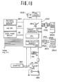
- Figs. 1A, 1B and 2 illustrate the preferred embodiment of the engine control system in accordance with the present invention.
- the controller 1000 comprises a microprocessor and is associated with another microprocessor 2500 which serves as a vehicle information system.
- the engine control system 1000 includes various sensors and detectors such as an engine speed sensor, an air flow meter, and various temperature sensors, for providing control parameters, a control unit and actuators for controlling various engine operations such as fuel metering, idle air flow, and spark ignition timing.
- the engine control system further includes a fault monitor for detecting faults in the control system. The fault monitor checks the operation of the control unit and the inputs from the sensors. The results of the check operation in the fault monitor are conducted to a non-volatile memory 1450 which is associated with the engine control system 1000.
- the check operation results are also fed to a display 1900 for control system fault indication through a data line 2022.
- the vehicle information system 2500 in the shown embodiment is adapted to compute travelling distance, travelling time, average vehicle speed and so on in order to display information related to the current vehicle trip.
- the vehicle information system 2500 is associated with an external input unit 2000 such as a keyboard and a display for information display.
- the vehicle information system 2500 is further associated with a non-volatile memory for storing the computed results.
- the non-volatile memories may be of Metal-Nitride-Oxide-Silicon (MNOS), Erasable Programable ROM (EPROM) or CMOS technologies.
- MNOS Metal-Nitride-Oxide-Silicon
- EPROM Erasable Programable ROM
- CMOS complementary metal-oxide-semiconductor
- the display can comprise various elements for indicating or warning when the system or sensors malfunction.
- the engine control system 1000 and the vehicle information system 2500 are connected to each other via a data transmission line connector 2510.
- the vehicle information system 2500 produces a read command when a read request is inputted to the input unit.
- the read command is fed to the engine control system through the data transmission line to read the data out of the non-volatile memory 1450.
- the read request is inputted to the input unit when the display 1900 indicates an error in the engine control system 1000.
- the data from the non-volatile memory 1450 is transferred to the vehicle information system 2500 via the fault monitor 1002 in the engine control system 1000 and the data transmission line.
- the vehicle information system 2500 distinguishes which sensor or element of the control unit in the engine control system is malfunctioning. Based on the detection of the faulty element or sensor, the vehicle information system 2500 feeds a fault display signal to the display. Therefore, in response to the fault display signal and in accordance with the fault display signal value, the display indicates the faulty sensor or element and the degree of error thereof.
- the fault monitor outputs data in response to the read command and holds the check program results until the next read command is received.
- the fault monitor connected in this manner to the vehicle information system according to the present invention is applicable not only to the foregoing engine control system but also to electronic control systems for automatic power transmission or for anti-skid control and so forth.
- Fig. 1A illustrates the electronic engine control system, so-called Electronic Concentrated Control System (ECCS) for a 6-cylinder reciprocating engine known as a Datsun L-type engine.
- ECCS Electronic Concentrated Control System
- fuel injection, spark ignition timing, exhaust gas recirculation rate and engine idling speed are all controlled.
- Fuel pressure is controlled by controlling fuel pump operation.
- each of the engine cylinders 12 of an internal combustion engine 10 communicates with an air induction system generally referred to by reference numeral 20.
- the air induction system 20 comprises an air intake duct 22 with an air cleaner 24 for cleaning atmospheric air, an air flow meter 26 provided downstream of the air intake duct 22 to measure the amount of intake air flowing therethrough, a throttle chamber 28 in which is disposed a throttle valve 30 cooperatively coupled with an accelerator pedal (not shown) so as to adjust the flow of intake air, and an intake manifold 32.
- the air flow meter 26 comprises a flap member 25 and a rheostat 27.
- the flap member 25 is pivotably supported in the air intake passage 20 so that its angular position varies according to the air flow rate.
- the flap member 25 rotates clockwise in Fig. 1A as the air flow rate increases.
- the rheostat 27 opposes the flap member 25 and generates an analog signal with a voltage level proportional to the intake air flow rate.
- the rheostat 27 is connected to an electrical power source and its resistance value is variable in correspondence to variation of the angular position of the flap member 25 depending in turn on variation of the air flow rate.
- flap-type air flow meter has been specifically illustrated, this can be replaced with any equivalent sensor, such as a hot wire sensor or a Karman vortex sensor, for example.
- a throttle angle sensor 31 is associated with the throttle valve 30.
- the throttle angle sensor 31 comprises a full-throttle switch which is closed when the throttle valve is open beyond a given open angle and an idle switch which is closed when the throttle valve is open less than a minimum value.
- Fuel injection through the fuel injectors 34 is controlled by an electromagnetic actuator (not shown) incorporated in each fuel injector.
- the actuator is electrically operated by the fuel injection control system which determines fuel injection quantity, fuel injection timing and so on in correspondence to engine operating conditions determined on the basis of measured engine operation parameters such as engine load, engine speed and so on.
- the fuel injector 34 is connected to a fuel pump 37 through a fuel feed line including a pressure regulator 39.
- the fuel pump 37 is controlled by means of a fuel pump relay 35.
- the fuel injector 34 is disposed in the intake manifold 32 in the shown embodiment, it is possible to locate it in the combustion chamber 12 in a per se well-known manner.
- An idle air or an auxiliary air intake passage 44 is provided in the air induction system 20.
- One end 46 of the idle air intake passage 44 opens between the air flow meter 26 and the throttle valve 30 and the other end 48 opens downstream of the throttle valve 30, near the intake manifold 32.
- the idle air intake passage 44 bypasses the throttle valve 30 and connects the upstream side of the throttle valve 30 to the intake manifold 32.
- An idle air control valve, generally referred to by reference numeral 50 is provided in the idle air intake passage 44.
- the idle air control valve 50 generally comprises two chambers 52 and 54 separated by a diaphragm 56.
- the idle air control valve 50 includes a poppet valve 58 disposed within a port 57 so as to be movable between two positions, one allowing communication between the upstream and downstream sides 43 and 45 of the idle air intake passage 44 and the other preventing communication therebetween.
- the idle air intake passage 44 is thus separated by the idle air control valve 50 into two regimes 43 and 45 respectively located upstream and downstream of the port 57 of the idle air control valve.
- the poppet valve 58 has a stem 60 which is secured to the diaphragm 56 so as to move therewith.
- the diaphragm 56 is biased downwards in the drawing, so as to displace the poppet valve 58 from a valve seat 62, by a helical compression coil spring 64 disposed within the chamber 52 of the valve means 50.
- the idle air control valve 50 is normally opened, and normally connects the regimes 43 and 45 of the idle air intake passage 44 to one another, via its valve port 57.
- the chamber 54 of the idle control valve 50 is open to the atmosphere.
- the chamber 52 of the idle air control valve 50 communicates through a vacuum passage 67 with a pressure regulating valve 68 serving as the control vacuum source.
- the pressure regulating valve 68 is separated generally into two chambers 66 and 70 by a diaphragm 72.
- the chamber 66 of the pressure regulating valve 68 also communicates with the downstream side of the throttle valve 30 through the vacuum passage 69 so as to reflect the level of the intake vacuum.
- the chamber 70 is open to the atmosphere.
- To the diaphragm 72 is secured a valve member 76 which opposes a valve seat 78 provided at the end of the passage 69.
- the chambers 66 and 70 receive helical compression springs 71 and 73 respectively.
- the position at which the springs 71 and 73 balance each other is referred to as the neutral position of the diaphragm 72.
- the chamber 66 can also be connected to an exhaust gas recirculation (EGR) rate control valve 116 which recirculates a fraction of the exhaust gas from an exhaust gas passage and exhaust gas recirculation passage to the intake manifold 32.
- EGR exhaust gas recirculation
- the diaphragm 72 moves upwards or downwards according to changes in the balance between the vacuum in the chamber 66 and the atmospheric pressure introduced into the chamber 70. This movement of the diaphragm 72, moves the valve member 76 toward or away from the valve seat 78.
- Another chamber 80 is also defined in the control valve 68, which chamber 80 communicates with the chamber 66 through a passage 82.
- the passage 82 is connected with the chamber 52 of the idle air control valve 50 through a control vacuum passage 84.
- the chamber 80 also communicates with the air intake passage 20 upstream of the throttle valve 30 through a passage 86 so as to be exposed to atmosphere.
- the chamber 80 is partitioned by a diaphragm 88 to which a magnetic valve member 90 is secured.
- the magnetic valve member 90 opposes a valve seat 92 formed at the end of the passage 82.
- the magnetic valve member 90 opposes an electromagnetic actuator 94, the duty cycle of which is controlled by a control pulse signal generated by the controller 1000.
- the control vacuum for controlling the opening degree of the valve member 58 of the idle air control valve 50 is regulated and supplied via the control vacuum passage 67.
- Spark ignition plugs 99 are installed in each of the engine, cylinders 12 to perform spark ignition at a controlled timing.
- Each ignition plug 99 is connected to a distributor 98 which receives high voltage power from an ignition coil 96.
- the distributor 98 is controlled by a spark advancer which advances or retards the spark ignition timing depending on engine operating conditions.
- An exhaust system for the engine exhaust gas comprises an exhaust manifold 100, an exhaust duct 102, an exhaust gas purifier 104, a muffler 106 and an exhaust vent.
- the exhaust manifold 100 opens toward the engine cylinders to draw engine exhaust gas therefrom.
- the exhaust duct 102 communicates with the exhaust manifold 100 and includes the exhaust gas purifier 104 and the muffler 106.
- the exhaust gas purifier 104 comprises a purifier housing 110 and a three-way catalytic converter 112 disposed within the purifier housing 110.
- the three-way catalytic converter 112 oxidizes monoxide carbon CO and hydrocarbons HC and reduces oxides of nitrogen NO x .
- An exhaust gas recirculation passage 114 which will be referred to hereafter as the EGR passage, is connected to the exhaust duct 102 upstream of the exhaust gas purifier 104.
- the EGR passage 114 communicates with the intake manifold 32 via the exhaust gas recirculation rate control valve 116 which will be referred as the EGR control valve.
- the EGR control valve 116 generally comprises a valve member 118 with a valve seat 120 form in the end of the EGR passage 114 adjacent the intake manifold 32.
- the valve member 118 is associated with a vacuum actuator 122 and is cooperatively connected to a diaphragm 124 of the vacuum actuator 122 via a stem 126.
- the diaphragm 124 divides the interior of the vacuum actuator 122 into two chambers 128 and 130.
- the chamber 128 communicates with the EGR passage 114 via a passage and the chamber 130 communicates with the regulating valve 68 via a control vacuum passage 134.
- a set spring 133 for biasing the diaphragm 124 is disposed within chamber 130.
- the control vacuum passage 134 is connected to a passage 136 connecting the vacuum chamber 66 to a chamber 138.
- One end of the passage 136 faces a valve member 140 secured to a diaphragm 142.
- a valve seat 143 is formed in the end of passage 136 to allow the valve member 140 to selectably seal passage 136.
- the valve member 140 has a stem 144 projecting into an electromagnetic actuator 146.
- the duty cycle of the electromagnetic actuator 146 is controlled to move the valve member 140 with respect to the valve seat 143 in response to a control signal generated by the controller to be described later.
- intake air is admitted to the passage 136 via the passage 86 at a controlled rate.
- the intake air admitted into the passage 136 is mixed with the intake vacuum admitted from intake passage 20 downstream of the throttle valve 30 via the vacuum induction passage 69 into the vacuum chamber 66, so as to produce the control vacuum.
- the control vacuum thus produced is conducted to the chamber 130 of the actuator 122 via the control vacuum passage 134 to control the operation of the EGR control valve 116.
- the exhaust gas is admitted into the intake manifold at a controlled rate.
- An air regulator 150 is provided near the throttle chamber 28 for regulating the intake air flowing through the throttle chamber.
- a carbon canister 152 is provided.
- the carbon canister 152 retains hydrocarbon vapor until the canister is purged by air via the purge line 154 to the intake manifold when the engine is running.
- the purge control valve 156 is closed. Only a small amount of purge air flows into the intake manifold through the constant purge orifice.
- the purge control valve 156 opens and the vapor is drawn into the intake manifold, through both the control orifice and the constant purge orifice.
- the carbon canister 152 can trap hydrocarbons due to the chemical action of the charcoal therein.
- the controller 1000 generally comprises a microcomputer and controls a fuel injection system, a spark ignition system, an EGR system and engine idling speed.
- the controller 1000 is connected to an engine coolant temperature sensor 220.
- the engine coolant temperature sensor 220 is usually disposed within a coolant chamber 222 in an engine cylinder block 224 in order to measure the engine coolant temperature.
- the engine coolant temperature sensor 220 produces an engine coolant temperature signal T w indicative of the measured engine coolant temperature.
- the engine coolant temperature signal T w is an analog signal with a voltage value proportional to the determined engine coolant temperature and is converted into a digital signal by a shaping circuit 1100 to adapt it for use by the digital controller 1000.
- the engine coolant temperature sensor 220 comprises a thermistor fitted onto a thermostat housing provided in the coolant circulation circuit.
- a crank angle sensor 230 is also connected to the controller 1000.
- the crank angle sensor 230 generally comprises a signal disc 232 secured to a crank shaft 234 for rotation therewith, and an electromagnetic pick-up 236.
- the crank angle sensor 230 produces a crank reference angle signal and a crank position angle signal.
- the crank reference angle signal is produced when the engine piston reaches the top dead center and the crank position angle signal is produced per a given unit of crank rotation, e.g., per 1 degree of crank rotation.
- a transmission neutral switch 240 is connected to the controller 1000.
- the transmission neutral switch 240 is secured to the transmission 242 to detect the neutral position thereof and produces a neutral signal when the transmission is in the neutral position.
- a vehicle speed sensor 250 is connected to the controller.
- the vehicle speed sensor 250 is located near a vehicle speed indicator 252 and produces a pulse train serving as a vehicle speed signal, the frequency of which is proportional to the vehicle speed.
- An exhaust gas temperature sensor 256 is installed in the exhaust gas purifier housing 110.
- the exhaust gas temperature sensor 256 monitors the exhaust gas temperature and produces an analog signal as an exhaust gas temperature signal, the voltage of which is proportional to the exhaust gas temperature.
- the exhaust gas temperature signal is supplied to the controller 1000 via a multiplexer and an analog-digital converter in which the exhaust gas temperature signal is converted into a digital signal suitable for use by the microcomputer.
- the digital signal indicative of the exhaust gas temperature has a frequency corresponding to the voltage of the exhaust gas temperature signal.
- an exhaust gas sensor 254 such as an oxygen sensor, hereafter referred to simply as the O2 sensor 254, is installed in the exhaust duct 102 upstream of the opening of the EGR passage 114.
- the O2 sensor 254 monitors the concentration of oxygen in the exhaust gas.
- the output of the O2 sensor goes high when the determined oxygen concentration exceeds a 1:1 ratio with other exhaust gas components and goes low when the oxygen concentration is less than a 1:1 ratio.
- the output of the O2 sensor is inputted to the microcomputer via the multiplexer and the analog-digital converter as a ⁇ -signal.
- the air flow meter 26 is connected to the controller 1000.
- the rheostat 27 of the air flow meter 26 outputs an analog signal with a voltage proportional to the intake air flow rate.
- the throttle angle sensor 31 is also connected to the microcomputer to supply the outputs of the full-throttle switch and the idle switch.
- the microcomputer in the controller 1000 is also connected with an air-conditioner switch 260, a starter switch 262, a starter 263 and a battery voltage sensor 264.
- the air-conditioner switch 260 is closed when the air-conditioner is operating.
- the starter switch 262 is closed when the starter 263 is operating.
- the battery voltage sensor 264 monitors the vehicle battery 259 and produces an analog signal with a voltage proportional to the determined battery voltage. The battery voltage signal is fed to the microcomputer via the multiplexer and the analog-digital converter.
- the controller 1000 controls the fuel injection amount and timing, the spark ignition timing, the EGR rate and the engine idling speed.
- the O2 sensor signal from the O2 sensor 254 is used to control the fuel injection quantity under stable engine conditions as determined with reference to the engine speed from the engine speed counter, the throttle valve angle position detected by the throttle angle sensor 31, the vehicle speed from the vehicle speed counter and so on.
- the fuel injection quantity is feedback controlled on the basis of the O2 sensor signal so that the air/fuel ratio can be controlled to the stoichiometric value.
- This method of fuel injection control is called ⁇ -control. If the engine is running under unstable conditions, the fuel injection quantity is generally determined on the basis of engine speed and intake air flow rate, the latter of which can be replaced by intake vacuum pressure downstream of the throttle valve. Under unstable engine conditions, the basic fuel injection quantity determined on the basis of engine speed and air flow rate is corrected according to other parameters such as air-conditioner switch position, transmission gear position, engine coolant temperature and so on.
- the spark ignition timing is generally controlled on the basis of engine speed, air flow rate, engine coolant temperature and so on, which effect to varying degrees the advance and retard of the spark advance.
- the EGR control is effected on the basis of engine speed, engine coolant temperature, ignition switch position and battery voltage.
- the recirculation rate of the exhaust gas is derived from the engine speed and a basic fuel injection quantity determined according to engine speed and engine load.
- the duty cycle of the EGR control valve is thus controlled in accordance with the determined recirculation rate.
- the idle engine speed is controlled predominantly on the basis of engine coolant temperature and engine load condition. Under relatively cold engine conditions, the engine speed is maintained at a predetermined value, determined with reference to the engine coolant temperature, resulting in fast idle operation. In the normal temperature range, the engine speed is feedback-controlled on the basis of the difference between the actual engine speed and a reference engine speed determined on the basis of engine temperature, engine load condition and other parameters.
- the controller 1000 also includes a fault monitor 1002.
- the fault monitor 1002 is a program stored in a memory 1450 and executed in a central processing unit (CPU) 1300.
- the controller 1000 is connectable with the external unit 2000 via a check connector 2010.
- the unit 2000 signals the controller 1000 to make the fault monitor operative in order to check a series of check items identified by inputs.
- the controller 1000 is also connected to the vehicle information system 2500 via the connector 2510.
- the fault monitor 1002 of the controller 1000 is connected to a fault indicator 1008 via line 180.
- the fault monitor 1002 produces a fault signal when an error occurs in any one of the check items.
- the fault indicator turns on in response to the fault signal to indicate malfunction of the engine control system.
- the fault monitor 1002 is associated with the non-volatile memory 1450 as set forth previously.
- check data from a series of check items are stored in the non-volatile memory 1450.
- the input unit of the vehicle information system When the fault indicator 1008 is turned on, the input unit of the vehicle information system generates and outputs the read request command to the engine control system in order to read the check data out of the non-volatile memory 1450.
- the vehicle information system 2500 feeds the fault display signal to the display in order to identify the specific faulty segment and error condition on the display.
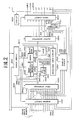
- Fig. 2 shows the controller 1000 of Fig. 1 in greater detail.
- the crank angle sensor 230, the vehicle speed sensor 250, the throttle angle sensor 31, the air-conditioner switch 260, the transmission neutral switch 240, the starter switch 262, the ignition switch, the air flow meter 26, the engine coolant temperature sensor 220, the exhaust gas sensor 254, the exhaust gas temperature sensor 256, the battery voltage sensor 264 are all connected to an input interface 1200 of the digital controller 1000 via a signal shaping circuit 1100.
- the shaping circuit 1100 eliminates noise in the sensor signals, absorbs surge voltages and shapes respective sensor signals.
- the interface 1200 includes a crank reference signal counter, an engine speed counter, a vehicle speed counter and analog-to-digital (A/D) converter with a multiplexer.
- A/D analog-to-digital
- the crank reference signal counter and the engine speed counter are both connected to the crank angle sensor 230 to receive therefrom the crank reference angle signal and the crank position angle signal respectively.
- the vehicle speed counter is adapted to count the pulses of the vehicle speed sensor signal to produce a digital value representative of the vehicle speed.
- the air flow meter 26, the engine coolant temperature sensor 220, the exhaust gas sensor 254, the exhaust gas temperature sensor 256, the battery voltage sensor 264 all produce analog signals and are connected to the analog-to-digital converter so that the corresponding analog signals can be converted to corresponding digital signals suitable for use in the digital controller 1000.
- the interface 1200 further includes a clock generator for controlling interface operations on a time-sharing basis, and a register for temporarily storing the inputted sensor signal values.
- the digital controller 1000 includes the central processing unit (CPU) 1300, a memory unit 1400 including random access memory (RAM) 1430 and programmable read-only memory (PROM) 1420, and an output interface 1500.
- the memory unit 1400 also includes non-volatile memory 1450, a holding memory 1440 and a masked ROM 1410.
- the CPU 1300 is connected to a clock generator including a crystal oscillator 1310 for controlling CPU operations on an incremental time basis.
- the CPU 1300 is also connected to each segment of the memory unit 1400, the register of the interface 1200 and the output interface 1500 via bus line 1320.
- the CPU 1300 executes programs stored in the masked ROM 1410 and the PROM 1420 in conjunction with input data read out from the register in the interface 1200. The results of execution of the programs are transferred to the output interface 1500 through the bus line 1320 for output.
- the masked ROM 1410 holds predetermined programs and initial program data.
- the PROM 1420 also stores programs and program data which are chosen initially depending upon the model of the vehicle and the type of engine.
- the RAM 1430 can renewably store data during execution of the programs and hold the results to be outputted. The contents of the RAM 1430 are cleared when power is turned off via the ignition switch.
- the non-volatile memory 1450 also stores data for the fault monitor. The contents of the non-volatile memory 1450 are maintained even when the ignition switch is turned off.
- the controller 1000 also includes an operation timer circuit 1350 for controlling arithmetic operation, execution of programs and initiation of interrupts of the CPU.
- the operation timer 1350 includes a multiplier for high-speed arithmetic operations, an interval timer for producing interrupt requests and a free-run counter which keeps track of the transition intervals between one engine control program and another in the CPU 1300 and the starting period of execution mode, so as to control the sequential execution of a plurality of control programs.
- the output interface 1500 includes an output register which temporarily stores the output data and a signal generator which produces control signals either with duty cycles defining the results of execution of the control programs in the CPU 1300 or with on/off switching characteristics.
- the signal generator of the output interface is connected to a drive circuit 1600.
- the drive circuit 1600 is a kind of amplifier for amplifying the output signals from the output interface and supplying the control signals to the actuators, such as fuel injectors 34, the actuator 94 for the idling speed control valve, and the actuator 146 for EGR control valve.
- the drive circuit 1600 is also connected to the display or indicator 1900 for fault indication, the external unit 2000 and the vehicle information system 2500.
- the drive circuit 1600 is connected to the external unit 2000 via the connector 2010 and data transmission lines 2023, 2022 and 2028.
- the drive circuit 1600 is connected to the vehicle information system 2500 via the connector 2510 and the data transmission lines 2521, 2522 and 2523.
- a back-up circuit 1700 is connected to the shaping circuit 1100 to receive data therefrom.
- the back-up circuit 1700 is connected to data lines to receive the crank reference angle signal, the engine temperature signal, starter switch on/off signal and the throttle valve close signal.
- the back-up circuit 1700 is connected to the data lines 1755, 1752 and 1751 via data lines 1713, 1712, 1711 and 1701 and a switching circuit 1750 which is, in turn, connected to the output interface 1500 via data lines 1515, 1512 and 1511.
- the drive circuit 1600 is connected via the actuator line 2028 to the back-up circuit 1700.
- the back-up circuit 1700 is responsive to the fault indication signal from the drive circuit 1600 to produce a switching signal.
- the switching circuit 1750 normally establishes communication between the data lines 1515, 1512 and 1511 and the lines 1755, 1752 and 1751 for normal engine control operation.
- the switching circuit 1750 is responsive to the switching signal from the back-up circuit 1700 via the data line 1701 to connect the data lines 1713, 1712 and 1711 with the data lines 1755, 1752 and 1751 to control the fuel pump 37, the spark advancer of the distributor 98 and the fuel injectors 34, respectively.
- a power circuit 1800 is connected to the vehicle battery 259 via a power switch 261 acting as a main power source to distribute power Vcc to the input interface 1200, CPU 1300, memory 1400 via line 1810, the output interface 1500 and so forth.
- the power circuit 1800 is also connected to the back-up circuit 1700 via line 1820.
- the power circuit 1800 produces a signal indicative of the ignition switch on/off positions and reset and halt signals for resetting the controller and temporarily disabling the controller 1000 respectively.
- the ignition on/off signal from the power circuit is fed to the input interface 1200 via a line 1830.
- the reset signal and the halt signal are fed to the bus-line 1320 via lines 1840 and 1850.
- the power circuit 1800 also supplies power to the input interface, the shaping circuit 1100, the drive circuit 1600 and the switching circuit 1750 via lines 1860 and 1870.
- the power circuit 1800 is also connected to an auxiliary power source which bypasses the power switch to supply power to holding memory 1440 via line 1880 even when the main power switch is turned off.
- the PROM 1420 stores various control programs for controlling engine operation.
- the PROM 1420 stores the check program for the fault monitor as one of its background jobs.
- the check program is executed whenever the CPU 1300 is not busy with the engine control programs.
- the results of execution of the check program are stored in the non-volatile memory 1450.
- the non-volatile memory 1450 has a plurality of addresses allocated for each of the check items.
- the check result data in the non-volatile memory 1450 are read out in response to a request from the input unit of the vehicle information system 2500 to provide indication or display data to the vehicle information system.
- crank angle signals from the crank angle sensor 230, the engine coolant temperature signal from the engine coolant temperature sensor 220, the air flow meter signal from the air flow meter 26 and so forth are checked as input signals.
- the idle air control signal, the EGR control signal, the fuel injection control signal and so forth are checked as output signals. There are various ways to check the input and output signals.
- the above-mentioned engine control system is so programmed as to set or update operation patterns of the specific engine from actual engine operation as indicated by the engine operation parameters sensed by the various sensors set forth above.
- the set operation pattern will be used to project engine behavior in terms of the corresponding control parameters.
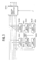
- This engine operation pattern setting procedure will be described below with reference to Fig. 3 which shows the operation of the control system in the form of a block diagram.
- the actual engine operation pattern is derived at a block 3100.
- the block 3100 receives as inputs the throttle position indicative signal from the throttle angle sensor 31, the air flow rate indicative signal from the air flow member 26, and the engine speed indicative signal derived from the crank position signal from the crank angle sensor 230.
- the throttle angle indicative signal values, the air flow rate indicative signal values and the engine speed indicative signal values are each sampled at given intervals over a given period to derive their respective variation patterns.
- the derived variation patterns are stored in a memory block in RAM as a series of relative values or amplitude, rather than as physical measurement readings.
- the variation patterns of the throttle position indicative signal value, the air flow rate indicative signal value and the engine speed indicative signal values will be referred to as "actual operation pattern data AOPD".
- the block 3400 receives as inputs the engine coolant temperature indicative signal from the engine coolant temperature sensor 220, the throttle position indicative signal from the throttle angle sensor 31, the air flow rate indicative signal from the air flow meter 26, the engine speed indicative signal, the air conditioner condition indicative signal from the air conditioner switch 260 and the transmission gear position indicative signal from the transmission neutral switch 240.
- the air conditioner position indicative signal and the transmission gear position indicative signal are binary, ON/OFF-type signals. For instance, the air conditioner indicative signal value remains HIGH as long as the air conditioner is operating and the transmission gear position signal value remains low as long as the transmission gear is in any gear other than neutral and/or park.
- the block 3400 is adapted to detect unstable operating states of engine such as near-stall, acceleration, deceleration, or transmission gear shift.
- the actual engine operating parameter values recorded, upon detection of an unstable state will be referred to as "actual engine operating condition data AEOCD".
- the actual engine operation pattern data AOPD is fed to a block 3300, in which the projected engine operation pattern is derived.
- the block 3300 is also connected to a block 3200 for deriving an engine operation influencing parameter EOIP, 3201.
- the block 3200 receives the air conditioner position indicative signal from the air conditioner switch 260 and the transmission gear position indicative signal from the transmission neutral switch 240.
- An engine operation influencing parameter which will be referred to as "engine operation influencing parameter EOIP” is derived from the air conditioner position indicative signal and the transmission gear position indicative signal.
- the block 3300 receives the actual operation pattern data AOPD from the block 3100 and the engine operation influencing parameter EOIP from the block 3200.
- the block 3300 possible variations in engine operation are projected on the basis of the actual operation pattern data and the engine operation influencing parameter.
- the block 3300 responds to changes in the engine operation influencing parameter EOIP by accessing an appropriate memory block in RAM to read previously set pattern data in terms of the engine operation influencing parameter EOIP and the actual operation pattern data AOPD.
- variation patterns of the throttle angle position, engine speed, intake air flow rate are projected in accordance with the engine operation influencing parameter, among others.
- the data representative of the variation patterns of the engine operating parameters will be referred to as "operating parameter variation data OPVD". If the operating parameter variation data OPVD are not initialized during vehicle assembly, the actual operation pattern data AOPD from the block 3100 may be set in the appropriate memory block in RAM as operating parameter variation data OPVD.
- a block 3500 receives the actual operation pattern data AOPD, 3101 and the actual engine operating condition data AEOCD, 3401 from the block 3400.
- the block 3500 responds to preselected specific engine operating conditions such as engine stall, acceleration, deceleration, or transmission gear shift as indicated by the actual engine operating condition data AEOCD.
- the block 3500 becomes active when any of the specific engine operating conditions is indicated by the actual engine operating condition data.
- the block 3500 triggers the CPU to record the actual operation pattern data AOPD in a corresponding memory block from among a plurality of memory blocks referred to as "pattern memory 1440" allocated to the actual operation pattern data of various engine operating conditions.
- pattern memory 1440 some of pattern data is initially set during installation of the control system in the vehicle in the factory.
- the data corresponding to the actual operation pattern data AOPD arrayed in terms of the actual engine operating condition data AEOCD will be referred to as "set engine operation pattern data SEOPD".
- the set engine operation pattern data SEOPD, 3501 is sent to a block 3600 in addition to the pattern memory 1440.
- the block 3600 also receives the operating parameter variation data OPVD, 3301 from the block 3300.
- the block 3600 projects possible future engine operation patterns on the basis of the set engine operation pattern data SEOPD and the operating parameter variation data OPVD, 3301. In practice, projection of future engine operating patterns is made by reading out one group of the set engine operation pattern data SEOPD corresponding to or most closely corresponding to the operating parameter variation data OPVD.
- the data projected by the block 3600 will be referred to hereafter as "projected engine operation pattern data PEOPD".
- the projected engine operation pattern data PEOPD, 3601 are used to correct various engine control signal values such as the fuel injection control signal, the ignition timing control signal, the EGR control signal, and the idling air or auxiliary air flow rate control signal derived in a block 3700. It should be appreciated that the block 3700 performs various engine control operations on the basis of the engine operating parameters.
- control signal values derived in the block 3700 are corrected in accordance with correction values derived on the basis of the projected engine operation patterns data PEOPD in order to optimize engine performance and minimize fuel consumption and pollution by exhaust gas. Also, the control signal values derived by the block 3700 are corrected in terms of the projected engine operation pattern data PEOPD for prevention of engine stalling when the projected engine operation pattern data indicates the possibility of stalling. Engine stall prevention procedures will be described in greater detail hereafter with reference to Figures 4 to 14.
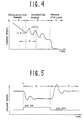
- Fig. 4 shows one typical pattern of variation of engine speed when the engine stalls.
- the throttle valve may be fully closed or nearly closed so that intake air enters only through the auxiliary air passage.
- fuel cut-off may be performed to conserve fuel.
- the clutch is released (in the case of manual power transmission) or the transmission is shifted to a lower gear ratio (in the case of automatic power transmission), so that the relative load on the engine is reduced to allow the engine to turn at a higher speed.
- the transition between engine deceleration and engine idling may be relatively smooth. In this case, engine speed drops gradually and steady towards the set engine idling speed. In this case, engine stalling will never occur and thus engine stall preventive procedures need not be performed.
- cycle-to-cycle fluctuation of the engine output torque will occur. Similar fluctuations may occur when the release timing of clutch of the manual transmission or the shift-down timing of the automatic transmission is too late, spark ignition timing is retarded too much, or the air induction rate fluctuates due to deposition of carbon or the like on the inner surfaces of the induction passage. Cycle-to-cycle fluctuations in engine output torque may cause hunting of engine speed, as shown in the TRANSITION RANGE B. This sometimes results in engine stalling, as indicated in the "ENGINE STALLING" range C.
- variation of the engine speed during the range D in Fig. 4 is set in the pattern memory 1440 as stall-representative set engine operation pattern data SEOPD.
- the possibility of engine stalling is recognized upon detection of engine speed variations corresponding to the engine stall-representative set engine operation pattern data SEOPD.
- engine stall preventive procedure is to be performed taken during the interval D in Fig. 4.
- the air conditioner switch is temporarily turned off, the air conditioner is temporarily disabled, or an auxiliary drive unit assisting the engine is activated to increase the relative torque of the engine.
- the engine stall representative set engine operation pattern data SEOPD is recognized during the interval E and the engine stall preventive procedure is performed during the interval F.
- Fig. 5 shows typical engine speed variations in response to changes in air conditioner operating state.
- the air conditioner is operating and a clutch of a compressor of the air conditioner is engaged to transmit engine output torque to the compressor.
- the compressor of the air conditioner acts as additional load on the engine. Due to this additional load, the engine speed remains relatively low.
- the air conditioner is not operating or the air conditioner compressor clutch is disengaged, a reduced load or essentially no load is applied to the engine through the air conditioner compressor. As overall load applied to the engine is thus reduced, the engine speed raises increases, as shown at H in Fig. 5.
- This pattern of variation of the engine speed relative to the air conditioner operating state is recorded as the operating parameter variation data OPVD in RAM.
- air conditioner dependent operating parameter variation data ACOPVD This operating parameter variation data OPVD to be accessed in terms of the air conditioner condition will be referred to as "air conditioner dependent operating parameter variation data ACOPVD". It is assumed that engine speed will vary according to the pattern illustrated in the range G in response to closure of the air conditioner switch. On the other hand, engine speed variations according to the pattern illustrated in the region H in response to opening of the air conditioner switch can be expected.
- the air conditioner dependent operation parameter variation data ACOPVD are used as part of the engine stall preventive operation whenever conditions matching the engine stall representative set engine operation pattern data SEOPD are recognized.
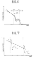
- Fig. 6,7 show the relationship between the engine stall representative set engine operation pattern data SEOPD and the air conditioner dependent operation parameter variation data ACOPVD.
- the engine speed is changing smoothly as illustrated by solid line a .
- air conditioner dependent operation parameter variation data ACOPVD as illustrated by the broken curve b is read out.
- the data SEOPD and ACOPVD are compared to calculate the area illustrated in hatching, which is representative of the integrated deviation therebetween. If area is smaller than a predetermined value, there is a high probability of engine stall if the stall preventive operation is not performed. Accordingly, the stall preventive operation is triggered. On the other hand, if the calculated area exceeds the predetermined value, the probability of engine stall is acceptably low. Therefore, in this case, stall preventive operation need not be performed.
- Figs. 8 to 14 are flowcharts of programs to be executed by the engine control system of Figs. 1 and 2.
- the flowcharts of Figs. 8 to 13 illustrate a sequence of routines for deriving the engine stall representative set engine operation pattern data to be used.
- the program formed by combining Figs. 8 to 13 will be referred to as "engine operation projecting program”.
- the program of Fig. 14 is executed to prevent the engine from stalling, and so will be referred to as "engine stall prevention program”.
- the engine operation projecting program is triggered at given intervals.
- the timing of execution of the engine operation projecting program is governed by the operation timer circuit 1350.
- the engine operation projecting program is separated into six portions which respectively correspond to the blocks 3100, 3200, 3300, 3400, 3500 and 3600.
- the routine in Fig. 8 represents the operation of the block 3100.
- each of the routines shown in Figs. 9 to 13 represent the operation of the blocks 3200, 3300, 3400, 3500 and 3600 respectively.
- the throttle angle position indicative signal value, the intake air flow rate indicative signal value and engine speed indicative signal values are processed to derive the actual engine operating condition AEOC, see Fig.8.
- the actual engine operating condition derived in the block 3151 is checked against various preset patterns EOP in ROM at a block 3152. If the actual engine condition matches one of the preset patterns EOP, the input engine operation parameter signals are sampled repeatedly over a predetermined, short period of time to derive an actual engine operation pattern data AOPD for each, at a block 3153.
- Fig. 3 recites that the block 3100 derives variation patterns and outputs pattern data for each of the input parameters, i.e. throttle angle variation, intake air flow rate variation and engine speed variation, hereinafter only the engine speed factor will be explained in detail for simplicity.
- the input parameters i.e. throttle angle variation, intake air flow rate variation and engine speed variation
- the sampled engine speed values to be used as the engine actual operation pattern data AOPD may be temporarily written in an appropriate register in CPU.
- the engine operation influencing parameter EOIP is checked. Though the operation of the block 3200 of Fig. 3 is described as to check the air conditioner position and the transmission gear position (transmission neutral position), for simplicity, only the air conditioner switch position will be considered in this description. Therefore, at the block 3251, the air conditioner switch 260 is checked to see whether or not the air conditioner switch 260 has just been operated. For instance, at the block 3251, the presence of a leading or trailing edge of an air conditioner switch signal pulse is checked for. If the air conditioner switch position remains unchanged, control passes to another routine for checking other engine operating influencing factors such as the transmission gear position.
- the air conditioner switch 260 is checked to see if it has just been closed or opened, in a block 3252. If the air conditioner has just been closed, the memory block storing air conditioner dependent operation parameter variation data ACOPVD is accessed to read out the engine speed variation pattern specific to closure of the air conditioner switch, such as is illustrated in the range G of Fig. 5, at a block 3253. On the other hand, if the air conditioner switch 260 has just been opened, the air conditioner dependent operation parameter variation data ACOPVD representative of the engine speed variation pattern in response to opening of the air conditioner switch 260 such as is illustrated in the range H of Fig. 5 is read out from the corresponding area of RAM, at a block 3254.
- the engine speed variation data used as the actual operation pattern data AOPD is read out in the block 3351.
- the current engine speed value is added to each of the engine speed variation data to form a projected engine speed behavior curve from the normalized recorded data.
- the engine speed at initial time points t2 or t3 in Fig. 7 are taken to be the initial engine speed values.
- the operating parameter variation data OPVD are then derived from the initial engine speed value obtained in the block 3351 and the air conditioner dependent operation parameter variation data ACOPVD, at a block 3352. This operating parameter variation data OPVD is illustrated in Fig. 7 by broken lines b and c.
- derivation of the operating parameter variation data OPVD is performed by adding the air conditioner dependent operation parameter variation data ACOPVD derived in either the block 3253 or the block 3254 to the initial engine speed value in place of actual operation pattern data AOPD.
- the engine stall operation involves only ON/OFF operations, such as switching off the air conditioner. In cases where, fuel supply or air flow are adjusted continuously to prevent stalling the full pattern data will be used for control over a specified period.
- the instantaneous engine speed N is checked to see if the speed is equal to or lower than 20 rpm. If so, engine stall is recognized and control passes to a block 3452.
- an engine stall representative flag FLES is set in a flag register 1302 in CPU 1300. Otherwise, i.e. when the engine speed is higher than 20 rpm, the engine is recognized to be running and the engine stall representative flag FLES in the flag register 1302 is reset or cancelled at a block 3453.
- the engine stall representative flag FLES is checked. If the engine stall representative flag FLES is set when checked in the block 3551, then the operating parameter pattern data AOPD is stored in the pattern memory 1440, in a block 3552.
- the memory blocks storing the engine stall representative set engine operation pattern data SEOPD are accessed in sequence. Each of the memory blocks storing the engine stall representative set engine operation pattern data will be referred to as a "SEOPD address".
- the first SEOPD address is accessed to read the first engine stall representative, set operation pattern data from the pattern memory 1440.
- the read out pattern data SEOPD are compared with the operating parameter variation data OPVD described with reference to Fig. 6.
- the hatched area in Fig. 6 is measured.
- the obtained area which will be hereafter referred to as "deviation indicative area DIA” is compared with a predetermined value Aref, at a block 3653. If the deviation indicative area DIA is equal to or less than the predetermined value Aref, then the pattern data SEOPD is latched at a block 3655.
- the SEOPD address to be accessed is shifted to the next one at a block 3654. Then, control returns to the block 3651 to read out the SEOPD data from the next SEOPD address.
- the blocks 3651, 3652, 3653 and 3654 form a loop to be repeated to check the operation parameter variation data OPVD against each SEOPD data pattern in sequence until the corresponding or the closest SEOPD pattern is found out.
- Fig. 14 shows the control program which is executed at regular intervals.
- the control program may be executed in synchronism with engine revolution in response to the crank reference signal.
- the engine stall representative flag FLES is checked at a block 3751.
- the controller performs normal engine control operations in a block 3752 to control auxiliary air flow, fuel injection, spark ignition, air/fuel mixture rate, exhaust gas recirculation and so forth on the basis of the various engine operation parameters, such as engine,load, engine speed, engine coolant temperature, oxygen concentration in the exhaust gas, and throttle valve angular position.
- the engine control operations performed in the block 3752 may be conventional and need not be discussed in detail here.
- a stall preventive routine represented by the blocks 3753, 3754 and 3755 is executed.
- an increment to the auxiliary airflow rate is realized.
- An auxiliary air flow control signal with increased duty cycle indicative of the incremented auxiliary air flow rate is thus transmitted to the actuator 94 of the pressure regulating valve 68.
- Increasing auxiliary air flow rate increases the total intake air flow rate and thus the air/fuel mixture supply to the engine combustion chamber. This results in an increase in engine output torque, preventing the engine from stalling.
- a target engine speed is modified to a higher value in a closed control loop.
- Increasing the target engine speed modifies the duty cycle of the control signal to increase the auxiliary air flow rate, resulting in an increase in the engine speed toward the modified target engine speed.
- an increase in the flow rate may be achieved by open loop control. Closed loop control would involve some response lag while open-loop control makes precise engine speed control more difficult. Therefore, in practice, the initial auxiliary air flow rate modification may be performed by open-loop control and thereafter control is switched to the closed loop control mode.
- the spark ignition control particularly for controlling spark advance, is performed.
- the spark ignition angle is advanced to increase the engine output torque.
- the dwell angle can be also increased to provide increased ignition power to the spark plugs. This reliably prevents misfiring in the engine combustion chamber and thereby ensures engine stall prevention.
- the exhaust gas recirculation rate is reduced. This can be achieved by reducing the duty cycle applied to actuator 146 of the pressure regulating valve 68. Reducing the non-combustionable component in the mixture in the engine cylinder, ensures ignition and self-sustained combustion in the engine combustion chamber.
- a switching relay may be inserted within air conditioner circuitry to interrupt the power supply temporarily during the engine stall preventing operation.
- an external driving unit can be connected to the engine to provide additional torque during the engine stall preventing operation.
- the increments to the auxiliary air flow rate, and the spark advance angle and the decrement to the exhaust gas recirculation rate may be adjusted continuously in accordance with the projected engine operation pattern data PEOPD.
- the increments to the auxiliary air flow rate, and the spark advance angle and/or the decrement to the exhaust gas recirculation rate may be functions of the PEOPD, or, alternatively, may be derived by table look-up in appropriate correction tables accessed in terms of PEOPD.
- the operation has been described in terms of monitoring solely variations in engine speed.
- practical application of this engine control technique should involve various engine operation parameters, such as throttle valve angular position, intake air flow rate, engine speed, vehicle speed, engine coolant temperature, air conditioner switch position, and transmission gear position.
- Each of this parameters may serve as one of several factors defining the actual engine operating condition as a measure of the current dynamic status of the engine.
- the engine operating condition may be recognized as a combination of these parameters.
- the set engine operation pattern data SEOPD will consist of numerous combinations of these parameters experienced duration or immediately prior to specific unstable engine operating conditions, such as engine stall, engine acceleration, deceleration and transmission gear shifting.
- various combinations of parameters would be preset to represent specific engine operating conditions.
- the normal engine control signals may be modified by correction values derived on the basis of the PEOPD corresponding to the recognized engine operating condition, i.e., the instantaneous dynamic status of the engine.
Landscapes
- Engineering & Computer Science (AREA)
- Chemical & Material Sciences (AREA)
- Combustion & Propulsion (AREA)
- Mechanical Engineering (AREA)
- General Engineering & Computer Science (AREA)
- Combined Controls Of Internal Combustion Engines (AREA)
- Electrical Control Of Air Or Fuel Supplied To Internal-Combustion Engine (AREA)
Description
- The invention relates to an engine control system for an internal combustion engine.
- In a prior art (US-A-4 373 501) engine control system for an internal combustion engine having an air supply passage by prepositioning an auxiliary air supply passage, a predicted transient in engine operation should be counteracted. This prior art system comprises a fuel control system taking into account the variations that occur in the quantity of fuel that is deposited in the liquid state in the intake passages of the engine. Thus, the fuel control facilitates transitions between two steady state operating conditions. The air/fuel ratio of the mixture in the intake passages varies depending upon the initial metering of fuel in proportion to the incoming air and also as a function of the net transfer of fuel from the surfaces of the intake passage to the inducted air/fuel mixture or vice versa. In this system, a stored look-up table is generated to govern the amount of change in the auxiliary air supply passage upon detection of a transient. After a transient is detected, the amount of air flow in the auxiliary air supply passage is altered as a function of the look-up table. As the transient passes, the air flow is adjusted in the auxiliary air supply passage to a value suitable for compensating for the next predicted transient. Finally, the system includes adaptively updating the look-up table to take into account engine operating conditions. The use of air control is advantageous compared to the control of the fuel flow because of increased speed of response offered by the auxiliary air supply passage.
- The object of the present invention is an improved engine control system having a fast response, and avoiding time lapse between measuring of actual engine parameters and a desired operation condition by predicting forthcoming engine operation conditions under consideration of the measured actual engine parameters.
- This object is solved by the features as claimed in
claim 1. - In accordance with the present invention the engine operation model pattern is a model of variation of parameters showing the probability of causing specific engine driving conditions whereby a predicted control of the engine with foresight of following engine behaviour or engine condition is performed. The control system adjusts the control procedures in response to preselected engine operating conditions in accordance with a projected engine operation pattern derived from the pre-recorded engine operation pattern data and the detected specific engine operating condition. The engine operation pattern data may be repeatedly updated and/or accumulated during engine operation and may be held in a memory of the control system even after the engine is turned off.
- The engine operating parameters may include the operation state of one or more vehicle components influencing engine operation, such as an air conditioner with a compressor driven by the engine and so acting as an additional load on the engine, or a transmission, the gear position of which can change engine operation significantly.
- Further developments of the invention are claimed in
claims 2 to 7. - The invention will be understood more fully from the detailed description given below and from the accompanying drawings of a preferred embodiment of the invention.
- In the drawings:
- Figs. 1A and 1B are diagrams of the overall structure of the preferred embodiment of an electronic automotive engine control system according to the present invention;
- Fig. 2 is a block diagram of a controller in the preferred embodiment of the engine control system of Figs. 1A and 1B;
- Fig. 3 is a block diagram of the operation of the control system of Fig. 2;
- Fig. 4 shows a typical pattern of engine speed variation resulting in engine stalling;
- Fig. 5 shows the variation of engine speed in response to switching an automotive air conditioner ON and OFF;
- Fig. 6 illustrates a method of selecting a preset engine operation pattern by comparing current and prerecorded variation patterns of engine operation parameters;
- Fig. 7 illustrates a method of applying the projected engine operation pattern to actual control;
- Figs. 8 to 13 are a sequence of flowcharts of an engine operation pattern projecting program to be executed by the controller of Fig. 2, each figure showing the operation of one of the blocks in Fig. 3; and
- Fig. 14 is a flowchart of an engine control program to be executed by the controller of Fig. 2.
-
- Figs. 1A, 1B and 2 illustrate the preferred embodiment of the engine control system in accordance with the present invention. The controller 1000 comprises a microprocessor and is associated with another
microprocessor 2500 which serves as a vehicle information system. The engine control system 1000 includes various sensors and detectors such as an engine speed sensor, an air flow meter, and various temperature sensors, for providing control parameters, a control unit and actuators for controlling various engine operations such as fuel metering, idle air flow, and spark ignition timing. The engine control system further includes a fault monitor for detecting faults in the control system. The fault monitor checks the operation of the control unit and the inputs from the sensors. The results of the check operation in the fault monitor are conducted to anon-volatile memory 1450 which is associated with the engine control system 1000. The check operation results are also fed to adisplay 1900 for control system fault indication through a data line 2022. On the other hand, thevehicle information system 2500 in the shown embodiment is adapted to compute travelling distance, travelling time, average vehicle speed and so on in order to display information related to the current vehicle trip. Thevehicle information system 2500 is associated with anexternal input unit 2000 such as a keyboard and a display for information display. Thevehicle information system 2500 is further associated with a non-volatile memory for storing the computed results. - In the shown embodiment, the non-volatile memories may be of Metal-Nitride-Oxide-Silicon (MNOS), Erasable Programable ROM (EPROM) or CMOS technologies. In addition, the display can comprise various elements for indicating or warning when the system or sensors malfunction.
- The engine control system 1000 and the
vehicle information system 2500 are connected to each other via a datatransmission line connector 2510. Thevehicle information system 2500 produces a read command when a read request is inputted to the input unit. The read command is fed to the engine control system through the data transmission line to read the data out of thenon-volatile memory 1450. The read request is inputted to the input unit when thedisplay 1900 indicates an error in the engine control system 1000. - The data from the
non-volatile memory 1450 is transferred to thevehicle information system 2500 via the fault monitor 1002 in the engine control system 1000 and the data transmission line. Thevehicle information system 2500 distinguishes which sensor or element of the control unit in the engine control system is malfunctioning. Based on the detection of the faulty element or sensor, thevehicle information system 2500 feeds a fault display signal to the display. Therefore, in response to the fault display signal and in accordance with the fault display signal value, the display indicates the faulty sensor or element and the degree of error thereof. - It should be appreciated that the fault monitor outputs data in response to the read command and holds the check program results until the next read command is received. In addition, the fault monitor connected in this manner to the vehicle information system according to the present invention is applicable not only to the foregoing engine control system but also to electronic control systems for automatic power transmission or for anti-skid control and so forth.
- Fig. 1A illustrates the electronic engine control system, so-called Electronic Concentrated Control System (ECCS) for a 6-cylinder reciprocating engine known as a Datsun L-type engine. In the shown control system, fuel injection, spark ignition timing, exhaust gas recirculation rate and engine idling speed are all controlled. Fuel pressure is controlled by controlling fuel pump operation.
- In Fig. 1A, each of the
engine cylinders 12 of aninternal combustion engine 10 communicates with an air induction system generally referred to byreference numeral 20. Theair induction system 20 comprises anair intake duct 22 with anair cleaner 24 for cleaning atmospheric air, anair flow meter 26 provided downstream of theair intake duct 22 to measure the amount of intake air flowing therethrough, athrottle chamber 28 in which is disposed athrottle valve 30 cooperatively coupled with an accelerator pedal (not shown) so as to adjust the flow of intake air, and anintake manifold 32. Theair flow meter 26 comprises aflap member 25 and arheostat 27. Theflap member 25 is pivotably supported in theair intake passage 20 so that its angular position varies according to the air flow rate. Specifically, theflap member 25 rotates clockwise in Fig. 1A as the air flow rate increases. Therheostat 27 opposes theflap member 25 and generates an analog signal with a voltage level proportional to the intake air flow rate. Therheostat 27 is connected to an electrical power source and its resistance value is variable in correspondence to variation of the angular position of theflap member 25 depending in turn on variation of the air flow rate. - Though a flap-type air flow meter has been specifically illustrated, this can be replaced with any equivalent sensor, such as a hot wire sensor or a Karman vortex sensor, for example.
- A
throttle angle sensor 31 is associated with thethrottle valve 30. Thethrottle angle sensor 31 comprises a full-throttle switch which is closed when the throttle valve is open beyond a given open angle and an idle switch which is closed when the throttle valve is open less than a minimum value. - Fuel injection through the
fuel injectors 34 is controlled by an electromagnetic actuator (not shown) incorporated in each fuel injector. The actuator is electrically operated by the fuel injection control system which determines fuel injection quantity, fuel injection timing and so on in correspondence to engine operating conditions determined on the basis of measured engine operation parameters such as engine load, engine speed and so on. Thefuel injector 34 is connected to afuel pump 37 through a fuel feed line including apressure regulator 39. Thefuel pump 37 is controlled by means of afuel pump relay 35. - It should be noted that, although the
fuel injector 34 is disposed in theintake manifold 32 in the shown embodiment, it is possible to locate it in thecombustion chamber 12 in a per se well-known manner. - An idle air or an auxiliary
air intake passage 44 is provided in theair induction system 20. Oneend 46 of the idleair intake passage 44 opens between theair flow meter 26 and thethrottle valve 30 and theother end 48 opens downstream of thethrottle valve 30, near theintake manifold 32. Thus the idleair intake passage 44 bypasses thethrottle valve 30 and connects the upstream side of thethrottle valve 30 to theintake manifold 32. An idle air control valve, generally referred to byreference numeral 50, is provided in the idleair intake passage 44. The idleair control valve 50 generally comprises twochambers diaphragm 56. The idleair control valve 50 includes a poppet valve 58 disposed within aport 57 so as to be movable between two positions, one allowing communication between the upstream anddownstream sides 43 and 45 of the idleair intake passage 44 and the other preventing communication therebetween. The idleair intake passage 44 is thus separated by the idleair control valve 50 into tworegimes 43 and 45 respectively located upstream and downstream of theport 57 of the idle air control valve. The poppet valve 58 has astem 60 which is secured to thediaphragm 56 so as to move therewith. Thediaphragm 56 is biased downwards in the drawing, so as to displace the poppet valve 58 from avalve seat 62, by a helicalcompression coil spring 64 disposed within thechamber 52 of the valve means 50. Thereby, the idleair control valve 50 is normally opened, and normally connects theregimes 43 and 45 of the idleair intake passage 44 to one another, via itsvalve port 57. - The
chamber 54 of theidle control valve 50 is open to the atmosphere. On the other hand, thechamber 52 of the idleair control valve 50 communicates through avacuum passage 67 with apressure regulating valve 68 serving as the control vacuum source. Thepressure regulating valve 68 is separated generally into twochambers diaphragm 72. Thechamber 66 of thepressure regulating valve 68 also communicates with the downstream side of thethrottle valve 30 through thevacuum passage 69 so as to reflect the level of the intake vacuum. Thechamber 70 is open to the atmosphere. To thediaphragm 72 is secured avalve member 76 which opposes avalve seat 78 provided at the end of thepassage 69. Thechambers springs diaphragm 72. It will be noted that thechamber 66 can also be connected to an exhaust gas recirculation (EGR)rate control valve 116 which recirculates a fraction of the exhaust gas from an exhaust gas passage and exhaust gas recirculation passage to theintake manifold 32. - The
diaphragm 72 moves upwards or downwards according to changes in the balance between the vacuum in thechamber 66 and the atmospheric pressure introduced into thechamber 70. This movement of thediaphragm 72, moves thevalve member 76 toward or away from thevalve seat 78. - Another
chamber 80 is also defined in thecontrol valve 68, whichchamber 80 communicates with thechamber 66 through apassage 82. Thepassage 82 is connected with thechamber 52 of the idleair control valve 50 through a control vacuum passage 84. On the other hand, thechamber 80 also communicates with theair intake passage 20 upstream of thethrottle valve 30 through apassage 86 so as to be exposed to atmosphere. Thechamber 80 is partitioned by adiaphragm 88 to which a magnetic valve member 90 is secured. The magnetic valve member 90 opposes avalve seat 92 formed at the end of thepassage 82. Also, the magnetic valve member 90 opposes anelectromagnetic actuator 94, the duty cycle of which is controlled by a control pulse signal generated by the controller 1000. Depending on the amount of atmospheric pressure introduced into thepassage 82 from thechamber 80, which is determined by the duty cycle of theelectromagnetic actuator 94 which in turn is determined by the duty cycle of the control pulse signal, the control vacuum for controlling the opening degree of the valve member 58 of the idleair control valve 50 is regulated and supplied via thecontrol vacuum passage 67. - Spark ignition plugs 99 are installed in each of the engine,
cylinders 12 to perform spark ignition at a controlled timing. Each ignition plug 99 is connected to adistributor 98 which receives high voltage power from anignition coil 96. Thedistributor 98 is controlled by a spark advancer which advances or retards the spark ignition timing depending on engine operating conditions. - An exhaust system for the engine exhaust gas comprises an
exhaust manifold 100, anexhaust duct 102, anexhaust gas purifier 104, amuffler 106 and an exhaust vent. Theexhaust manifold 100 opens toward the engine cylinders to draw engine exhaust gas therefrom. Theexhaust duct 102 communicates with theexhaust manifold 100 and includes theexhaust gas purifier 104 and themuffler 106. In the shown embodiment, theexhaust gas purifier 104 comprises apurifier housing 110 and a three-waycatalytic converter 112 disposed within thepurifier housing 110. The three-waycatalytic converter 112 oxidizes monoxide carbon CO and hydrocarbons HC and reduces oxides of nitrogen NOx. - An exhaust
gas recirculation passage 114, which will be referred to hereafter as the EGR passage, is connected to theexhaust duct 102 upstream of theexhaust gas purifier 104. TheEGR passage 114 communicates with theintake manifold 32 via the exhaust gas recirculationrate control valve 116 which will be referred as the EGR control valve. TheEGR control valve 116 generally comprises avalve member 118 with avalve seat 120 form in the end of theEGR passage 114 adjacent theintake manifold 32. Thevalve member 118 is associated with avacuum actuator 122 and is cooperatively connected to adiaphragm 124 of thevacuum actuator 122 via astem 126. Thediaphragm 124 divides the interior of thevacuum actuator 122 into twochambers chamber 128 communicates with theEGR passage 114 via a passage and thechamber 130 communicates with the regulatingvalve 68 via acontrol vacuum passage 134. Aset spring 133 for biasing thediaphragm 124 is disposed withinchamber 130. Thecontrol vacuum passage 134 is connected to apassage 136 connecting thevacuum chamber 66 to a chamber 138. One end of thepassage 136 faces avalve member 140 secured to a diaphragm 142. A valve seat 143 is formed in the end ofpassage 136 to allow thevalve member 140 toselectably seal passage 136. Thevalve member 140 has astem 144 projecting into an electromagnetic actuator 146. - The duty cycle of the electromagnetic actuator 146 is controlled to move the
valve member 140 with respect to the valve seat 143 in response to a control signal generated by the controller to be described later. According to the instantaneous position of thevalve member 140, intake air is admitted to thepassage 136 via thepassage 86 at a controlled rate. The intake air admitted into thepassage 136 is mixed with the intake vacuum admitted fromintake passage 20 downstream of thethrottle valve 30 via thevacuum induction passage 69 into thevacuum chamber 66, so as to produce the control vacuum. The control vacuum thus produced is conducted to thechamber 130 of theactuator 122 via thecontrol vacuum passage 134 to control the operation of theEGR control valve 116. Thereby, the exhaust gas is admitted into the intake manifold at a controlled rate. - An
air regulator 150 is provided near thethrottle chamber 28 for regulating the intake air flowing through the throttle chamber. Also, acarbon canister 152 is provided. Thecarbon canister 152 retains hydrocarbon vapor until the canister is purged by air via thepurge line 154 to the intake manifold when the engine is running. When the engine is idling, thepurge control valve 156 is closed. Only a small amount of purge air flows into the intake manifold through the constant purge orifice. As the engine speed increases, and the ported vacuum becomes stronger, thepurge control valve 156 opens and the vapor is drawn into the intake manifold, through both the control orifice and the constant purge orifice. Thecarbon canister 152 can trap hydrocarbons due to the chemical action of the charcoal therein. - As shown in Fig. 1B, the controller 1000 generally comprises a microcomputer and controls a fuel injection system, a spark ignition system, an EGR system and engine idling speed. The controller 1000 is connected to an engine
coolant temperature sensor 220. The enginecoolant temperature sensor 220 is usually disposed within acoolant chamber 222 in anengine cylinder block 224 in order to measure the engine coolant temperature. The enginecoolant temperature sensor 220 produces an engine coolant temperature signal Tw indicative of the measured engine coolant temperature. The engine coolant temperature signal Tw is an analog signal with a voltage value proportional to the determined engine coolant temperature and is converted into a digital signal by ashaping circuit 1100 to adapt it for use by the digital controller 1000. - Generally speaking, the engine
coolant temperature sensor 220 comprises a thermistor fitted onto a thermostat housing provided in the coolant circulation circuit. - A
crank angle sensor 230 is also connected to the controller 1000. Thecrank angle sensor 230 generally comprises asignal disc 232 secured to a crankshaft 234 for rotation therewith, and an electromagnetic pick-up 236. Thecrank angle sensor 230 produces a crank reference angle signal and a crank position angle signal. As is well known, the crank reference angle signal is produced when the engine piston reaches the top dead center and the crank position angle signal is produced per a given unit of crank rotation, e.g., per 1 degree of crank rotation. - A transmission
neutral switch 240 is connected to the controller 1000. The transmissionneutral switch 240 is secured to thetransmission 242 to detect the neutral position thereof and produces a neutral signal when the transmission is in the neutral position. - Also, a
vehicle speed sensor 250 is connected to the controller. Thevehicle speed sensor 250 is located near avehicle speed indicator 252 and produces a pulse train serving as a vehicle speed signal, the frequency of which is proportional to the vehicle speed. - An exhaust
gas temperature sensor 256 is installed in the exhaustgas purifier housing 110. The exhaustgas temperature sensor 256 monitors the exhaust gas temperature and produces an analog signal as an exhaust gas temperature signal, the voltage of which is proportional to the exhaust gas temperature. The exhaust gas temperature signal is supplied to the controller 1000 via a multiplexer and an analog-digital converter in which the exhaust gas temperature signal is converted into a digital signal suitable for use by the microcomputer. The digital signal indicative of the exhaust gas temperature has a frequency corresponding to the voltage of the exhaust gas temperature signal. - In addition, an
exhaust gas sensor 254 such as an oxygen sensor, hereafter referred to simply as theO₂ sensor 254, is installed in theexhaust duct 102 upstream of the opening of theEGR passage 114. TheO₂ sensor 254 monitors the concentration of oxygen in the exhaust gas. The output of the O₂ sensor goes high when the determined oxygen concentration exceeds a 1:1 ratio with other exhaust gas components and goes low when the oxygen concentration is less than a 1:1 ratio. The output of the O₂ sensor is inputted to the microcomputer via the multiplexer and the analog-digital converter as a λ-signal. - In addition, the
air flow meter 26 is connected to the controller 1000. Therheostat 27 of theair flow meter 26 outputs an analog signal with a voltage proportional to the intake air flow rate. Thethrottle angle sensor 31 is also connected to the microcomputer to supply the outputs of the full-throttle switch and the idle switch. - As shown in block form in Fig. 1B, the microcomputer in the controller 1000 is also connected with an air-
conditioner switch 260, astarter switch 262, astarter 263 and abattery voltage sensor 264. The air-conditioner switch 260 is closed when the air-conditioner is operating. Also, thestarter switch 262 is closed when thestarter 263 is operating. Thebattery voltage sensor 264 monitors thevehicle battery 259 and produces an analog signal with a voltage proportional to the determined battery voltage. The battery voltage signal is fed to the microcomputer via the multiplexer and the analog-digital converter. - In the shown embodiment, the controller 1000 controls the fuel injection amount and timing, the spark ignition timing, the EGR rate and the engine idling speed.
- The O₂ sensor signal from the
O₂ sensor 254 is used to control the fuel injection quantity under stable engine conditions as determined with reference to the engine speed from the engine speed counter, the throttle valve angle position detected by thethrottle angle sensor 31, the vehicle speed from the vehicle speed counter and so on. Under stable engine conditions, the fuel injection quantity is feedback controlled on the basis of the O₂ sensor signal so that the air/fuel ratio can be controlled to the stoichiometric value. This method of fuel injection control is called λ-control. If the engine is running under unstable conditions, the fuel injection quantity is generally determined on the basis of engine speed and intake air flow rate, the latter of which can be replaced by intake vacuum pressure downstream of the throttle valve. Under unstable engine conditions, the basic fuel injection quantity determined on the basis of engine speed and air flow rate is corrected according to other parameters such as air-conditioner switch position, transmission gear position, engine coolant temperature and so on. - The spark ignition timing is generally controlled on the basis of engine speed, air flow rate, engine coolant temperature and so on, which effect to varying degrees the advance and retard of the spark advance.
- The EGR control is effected on the basis of engine speed, engine coolant temperature, ignition switch position and battery voltage. The recirculation rate of the exhaust gas is derived from the engine speed and a basic fuel injection quantity determined according to engine speed and engine load. The duty cycle of the EGR control valve is thus controlled in accordance with the determined recirculation rate.
- The idle engine speed is controlled predominantly on the basis of engine coolant temperature and engine load condition. Under relatively cold engine conditions, the engine speed is maintained at a predetermined value, determined with reference to the engine coolant temperature, resulting in fast idle operation. In the normal temperature range, the engine speed is feedback-controlled on the basis of the difference between the actual engine speed and a reference engine speed determined on the basis of engine temperature, engine load condition and other parameters.
- As shown in Fig. 1A and 1B, the controller 1000 also includes a fault monitor 1002. In practice, the fault monitor 1002 is a program stored in a
memory 1450 and executed in a central processing unit (CPU) 1300. The controller 1000 is connectable with theexternal unit 2000 via acheck connector 2010. Theunit 2000 signals the controller 1000 to make the fault monitor operative in order to check a series of check items identified by inputs. The controller 1000 is also connected to thevehicle information system 2500 via theconnector 2510. - The fault monitor 1002 of the controller 1000 is connected to a
fault indicator 1008 via line 180. The fault monitor 1002 produces a fault signal when an error occurs in any one of the check items. The fault indicator turns on in response to the fault signal to indicate malfunction of the engine control system. The fault monitor 1002 is associated with thenon-volatile memory 1450 as set forth previously. Upon execution of the check program, check data from a series of check items are stored in thenon-volatile memory 1450. When thefault indicator 1008 is turned on, the input unit of the vehicle information system generates and outputs the read request command to the engine control system in order to read the check data out of thenon-volatile memory 1450. On the basis of the retrieved check data, thevehicle information system 2500 feeds the fault display signal to the display in order to identify the specific faulty segment and error condition on the display. - Fig. 2 shows the controller 1000 of Fig. 1 in greater detail. The
crank angle sensor 230, thevehicle speed sensor 250, thethrottle angle sensor 31, the air-conditioner switch 260, the transmissionneutral switch 240, thestarter switch 262, the ignition switch, theair flow meter 26, the enginecoolant temperature sensor 220, theexhaust gas sensor 254, the exhaustgas temperature sensor 256, thebattery voltage sensor 264 are all connected to aninput interface 1200 of the digital controller 1000 via asignal shaping circuit 1100. Theshaping circuit 1100 eliminates noise in the sensor signals, absorbs surge voltages and shapes respective sensor signals. Theinterface 1200 includes a crank reference signal counter, an engine speed counter, a vehicle speed counter and analog-to-digital (A/D) converter with a multiplexer. The crank reference signal counter and the engine speed counter are both connected to thecrank angle sensor 230 to receive therefrom the crank reference angle signal and the crank position angle signal respectively. The vehicle speed counter is adapted to count the pulses of the vehicle speed sensor signal to produce a digital value representative of the vehicle speed. Theair flow meter 26, the enginecoolant temperature sensor 220, theexhaust gas sensor 254, the exhaustgas temperature sensor 256, thebattery voltage sensor 264 all produce analog signals and are connected to the analog-to-digital converter so that the corresponding analog signals can be converted to corresponding digital signals suitable for use in the digital controller 1000. - The
interface 1200 further includes a clock generator for controlling interface operations on a time-sharing basis, and a register for temporarily storing the inputted sensor signal values. - As usual, the digital controller 1000 includes the central processing unit (CPU) 1300, a
memory unit 1400 including random access memory (RAM) 1430 and programmable read-only memory (PROM) 1420, and anoutput interface 1500. As shown in Fig. 2, thememory unit 1400 also includesnon-volatile memory 1450, a holding memory 1440 and amasked ROM 1410. TheCPU 1300 is connected to a clock generator including acrystal oscillator 1310 for controlling CPU operations on an incremental time basis. TheCPU 1300 is also connected to each segment of thememory unit 1400, the register of theinterface 1200 and theoutput interface 1500 via bus line 1320. TheCPU 1300 executes programs stored in themasked ROM 1410 and thePROM 1420 in conjunction with input data read out from the register in theinterface 1200. The results of execution of the programs are transferred to theoutput interface 1500 through the bus line 1320 for output. - As set forth previously, the
masked ROM 1410 holds predetermined programs and initial program data. ThePROM 1420 also stores programs and program data which are chosen initially depending upon the model of the vehicle and the type of engine. TheRAM 1430 can renewably store data during execution of the programs and hold the results to be outputted. The contents of theRAM 1430 are cleared when power is turned off via the ignition switch. As stated previously, thenon-volatile memory 1450 also stores data for the fault monitor. The contents of thenon-volatile memory 1450 are maintained even when the ignition switch is turned off. - The controller 1000 also includes an
operation timer circuit 1350 for controlling arithmetic operation, execution of programs and initiation of interrupts of the CPU. Theoperation timer 1350 includes a multiplier for high-speed arithmetic operations, an interval timer for producing interrupt requests and a free-run counter which keeps track of the transition intervals between one engine control program and another in theCPU 1300 and the starting period of execution mode, so as to control the sequential execution of a plurality of control programs. - The
output interface 1500 includes an output register which temporarily stores the output data and a signal generator which produces control signals either with duty cycles defining the results of execution of the control programs in theCPU 1300 or with on/off switching characteristics. - The signal generator of the output interface is connected to a
drive circuit 1600. Thedrive circuit 1600 is a kind of amplifier for amplifying the output signals from the output interface and supplying the control signals to the actuators, such asfuel injectors 34, theactuator 94 for the idling speed control valve, and the actuator 146 for EGR control valve. Thedrive circuit 1600 is also connected to the display orindicator 1900 for fault indication, theexternal unit 2000 and thevehicle information system 2500. Thedrive circuit 1600 is connected to theexternal unit 2000 via theconnector 2010 and data transmission lines 2023, 2022 and 2028. On the other hand, thedrive circuit 1600 is connected to thevehicle information system 2500 via theconnector 2510 and thedata transmission lines - A back-
up circuit 1700 is connected to theshaping circuit 1100 to receive data therefrom. In practice, the back-up circuit 1700 is connected to data lines to receive the crank reference angle signal, the engine temperature signal, starter switch on/off signal and the throttle valve close signal. In turn, the back-up circuit 1700 is connected to thedata lines data lines switching circuit 1750 which is, in turn, connected to theoutput interface 1500 viadata lines drive circuit 1600 is connected via the actuator line 2028 to the back-up circuit 1700. The back-up circuit 1700 is responsive to the fault indication signal from thedrive circuit 1600 to produce a switching signal. Theswitching circuit 1750 normally establishes communication between thedata lines lines switching circuit 1750 is responsive to the switching signal from the back-up circuit 1700 via thedata line 1701 to connect thedata lines data lines fuel pump 37, the spark advancer of thedistributor 98 and thefuel injectors 34, respectively. - A
power circuit 1800 is connected to thevehicle battery 259 via apower switch 261 acting as a main power source to distribute power Vcc to theinput interface 1200,CPU 1300,memory 1400 vialine 1810, theoutput interface 1500 and so forth. Thepower circuit 1800 is also connected to the back-up circuit 1700 vialine 1820. Thepower circuit 1800 produces a signal indicative of the ignition switch on/off positions and reset and halt signals for resetting the controller and temporarily disabling the controller 1000 respectively. The ignition on/off signal from the power circuit is fed to theinput interface 1200 via aline 1830. On the other hand, the reset signal and the halt signal are fed to the bus-line 1320 vialines 1840 and 1850. Thepower circuit 1800 also supplies power to the input interface, theshaping circuit 1100, thedrive circuit 1600 and theswitching circuit 1750 vialines power circuit 1800 is also connected to an auxiliary power source which bypasses the power switch to supply power to holding memory 1440 vialine 1880 even when the main power switch is turned off. - In the engine control system, the
PROM 1420 stores various control programs for controlling engine operation. In addition, thePROM 1420 stores the check program for the fault monitor as one of its background jobs. The check program is executed whenever theCPU 1300 is not busy with the engine control programs. The results of execution of the check program are stored in thenon-volatile memory 1450. Thenon-volatile memory 1450 has a plurality of addresses allocated for each of the check items. The check result data in thenon-volatile memory 1450 are read out in response to a request from the input unit of thevehicle information system 2500 to provide indication or display data to the vehicle information system. - On the other hand, in order to check each check item, particularly for accurately checking input and output signals of the engine control system 1000, it is necessary to eliminate influence due to noise created by various vehicle devices, such as the ignition system. Therefore, the time spent checking each check item must be long enough to compensate for the influence of noise.
- In the check program, the crank angle signals from the
crank angle sensor 230, the engine coolant temperature signal from the enginecoolant temperature sensor 220, the air flow meter signal from theair flow meter 26 and so forth are checked as input signals. On the other hand, the idle air control signal, the EGR control signal, the fuel injection control signal and so forth are checked as output signals. There are various ways to check the input and output signals. - On the other hand, the above-mentioned engine control system is so programmed as to set or update operation patterns of the specific engine from actual engine operation as indicated by the engine operation parameters sensed by the various sensors set forth above. The set operation pattern will be used to project engine behavior in terms of the corresponding control parameters. This engine operation pattern setting procedure will be described below with reference to Fig. 3 which shows the operation of the control system in the form of a block diagram.
- The actual engine operation pattern is derived at a
block 3100. In order to derive the actual engine operation pattern of the engine, theblock 3100 receives as inputs the throttle position indicative signal from thethrottle angle sensor 31, the air flow rate indicative signal from theair flow member 26, and the engine speed indicative signal derived from the crank position signal from thecrank angle sensor 230. The throttle angle indicative signal values, the air flow rate indicative signal values and the engine speed indicative signal values are each sampled at given intervals over a given period to derive their respective variation patterns. The derived variation patterns are stored in a memory block in RAM as a series of relative values or amplitude, rather than as physical measurement readings. Throughout the disclosure, the variation patterns of the throttle position indicative signal value, the air flow rate indicative signal value and the engine speed indicative signal values will be referred to as "actual operation pattern data AOPD". - Recognition of an actual pertinent engine operating state is performed at a
block 3400. In order to recognize this engine operating state presaging engine stall, theblock 3400 receives as inputs the engine coolant temperature indicative signal from the enginecoolant temperature sensor 220, the throttle position indicative signal from thethrottle angle sensor 31, the air flow rate indicative signal from theair flow meter 26, the engine speed indicative signal, the air conditioner condition indicative signal from theair conditioner switch 260 and the transmission gear position indicative signal from the transmissionneutral switch 240. As set forth above, the air conditioner position indicative signal and the transmission gear position indicative signal are binary, ON/OFF-type signals. For instance, the air conditioner indicative signal value remains HIGH as long as the air conditioner is operating and the transmission gear position signal value remains low as long as the transmission gear is in any gear other than neutral and/or park. Theblock 3400 is adapted to detect unstable operating states of engine such as near-stall, acceleration, deceleration, or transmission gear shift. The actual engine operating parameter values recorded, upon detection of an unstable state will be referred to as "actual engine operating condition data AEOCD". - The actual engine operation pattern data AOPD is fed to a
block 3300, in which the projected engine operation pattern is derived. Theblock 3300 is also connected to ablock 3200 for deriving an engine operation influencing parameter EOIP, 3201. Theblock 3200 receives the air conditioner position indicative signal from theair conditioner switch 260 and the transmission gear position indicative signal from the transmissionneutral switch 240. An engine operation influencing parameter, which will be referred to as "engine operation influencing parameter EOIP" is derived from the air conditioner position indicative signal and the transmission gear position indicative signal. Theblock 3300 receives the actual operation pattern data AOPD from theblock 3100 and the engine operation influencing parameter EOIP from theblock 3200. In theblock 3300, possible variations in engine operation are projected on the basis of the actual operation pattern data and the engine operation influencing parameter. Theblock 3300 responds to changes in the engine operation influencing parameter EOIP by accessing an appropriate memory block in RAM to read previously set pattern data in terms of the engine operation influencing parameter EOIP and the actual operation pattern data AOPD. In practice, variation patterns of the throttle angle position, engine speed, intake air flow rate are projected in accordance with the engine operation influencing parameter, among others. The data representative of the variation patterns of the engine operating parameters will be referred to as "operating parameter variation data OPVD". If the operating parameter variation data OPVD are not initialized during vehicle assembly, the actual operation pattern data AOPD from theblock 3100 may be set in the appropriate memory block in RAM as operating parameter variation data OPVD. - A
block 3500 receives the actual operation pattern data AOPD, 3101 and the actual engine operating condition data AEOCD, 3401 from theblock 3400. Theblock 3500 responds to preselected specific engine operating conditions such as engine stall, acceleration, deceleration, or transmission gear shift as indicated by the actual engine operating condition data AEOCD. Theblock 3500 becomes active when any of the specific engine operating conditions is indicated by the actual engine operating condition data. Theblock 3500 triggers the CPU to record the actual operation pattern data AOPD in a corresponding memory block from among a plurality of memory blocks referred to as "pattern memory 1440" allocated to the actual operation pattern data of various engine operating conditions. In the pattern memory 1440, some of pattern data is initially set during installation of the control system in the vehicle in the factory. The data corresponding to the actual operation pattern data AOPD arrayed in terms of the actual engine operating condition data AEOCD will be referred to as "set engine operation pattern data SEOPD". - The set engine operation pattern data SEOPD, 3501 is sent to a
block 3600 in addition to the pattern memory 1440. Theblock 3600 also receives the operating parameter variation data OPVD, 3301 from theblock 3300. Theblock 3600 projects possible future engine operation patterns on the basis of the set engine operation pattern data SEOPD and the operating parameter variation data OPVD, 3301. In practice, projection of future engine operating patterns is made by reading out one group of the set engine operation pattern data SEOPD corresponding to or most closely corresponding to the operating parameter variation data OPVD. The data projected by theblock 3600 will be referred to hereafter as "projected engine operation pattern data PEOPD". - The projected engine operation pattern data PEOPD, 3601 are used to correct various engine control signal values such as the fuel injection control signal, the ignition timing control signal, the EGR control signal, and the idling air or auxiliary air flow rate control signal derived in a
block 3700. It should be appreciated that theblock 3700 performs various engine control operations on the basis of the engine operating parameters. - The control signal values derived in the
block 3700 are corrected in accordance with correction values derived on the basis of the projected engine operation patterns data PEOPD in order to optimize engine performance and minimize fuel consumption and pollution by exhaust gas. Also, the control signal values derived by theblock 3700 are corrected in terms of the projected engine operation pattern data PEOPD for prevention of engine stalling when the projected engine operation pattern data indicates the possibility of stalling. Engine stall prevention procedures will be described in greater detail hereafter with reference to Figures 4 to 14. - Fig. 4 shows one typical pattern of variation of engine speed when the engine stalls. In DECELERATION RANGE A, the throttle valve may be fully closed or nearly closed so that intake air enters only through the auxiliary air passage. At the same time, fuel cut-off may be performed to conserve fuel. At the end of the range A, the clutch is released (in the case of manual power transmission) or the transmission is shifted to a lower gear ratio (in the case of automatic power transmission), so that the relative load on the engine is reduced to allow the engine to turn at a higher speed. If the engine including the air induction system, the fuel injection system, the exhaust system and so forth, are operating well, the transition between engine deceleration and engine idling may be relatively smooth. In this case, engine speed drops gradually and steady towards the set engine idling speed. In this case, engine stalling will never occur and thus engine stall preventive procedures need not be performed.
- However, if the fuel supply system is not operating well, allowing the air/fuel mixture rate to deviate far from stoichiometry, cycle-to-cycle fluctuation of the engine output torque will occur. Similar fluctuations may occur when the release timing of clutch of the manual transmission or the shift-down timing of the automatic transmission is too late, spark ignition timing is retarded too much, or the air induction rate fluctuates due to deposition of carbon or the like on the inner surfaces of the induction passage. Cycle-to-cycle fluctuations in engine output torque may cause hunting of engine speed, as shown in the TRANSITION RANGE B. This sometimes results in engine stalling, as indicated in the "ENGINE STALLING" range C.
- According to the present invention, variation of the engine speed during the range D in Fig. 4 is set in the pattern memory 1440 as stall-representative set engine operation pattern data SEOPD. In the shown example, the possibility of engine stalling is recognized upon detection of engine speed variations corresponding to the engine stall-representative set engine operation pattern data SEOPD. In order to prevent the engine from falling into engine stalling pattern, engine stall preventive procedure is to be performed taken during the interval D in Fig. 4. In this engine stall preventive procedure, the air conditioner switch is temporarily turned off, the air conditioner is temporarily disabled, or an auxiliary drive unit assisting the engine is activated to increase the relative torque of the engine.
- In practice, the engine stall representative set engine operation pattern data SEOPD is recognized during the interval E and the engine stall preventive procedure is performed during the interval F.
- Fig. 5 shows typical engine speed variations in response to changes in air conditioner operating state. During an interval in Fig. 5, the air conditioner is operating and a clutch of a compressor of the air conditioner is engaged to transmit engine output torque to the compressor. In, this case, the compressor of the air conditioner acts as additional load on the engine. Due to this additional load, the engine speed remains relatively low. When the air conditioner is not operating or the air conditioner compressor clutch is disengaged, a reduced load or essentially no load is applied to the engine through the air conditioner compressor. As overall load applied to the engine is thus reduced, the engine speed raises increases, as shown at H in Fig. 5. This pattern of variation of the engine speed relative to the air conditioner operating state is recorded as the operating parameter variation data OPVD in RAM. This operating parameter variation data OPVD to be accessed in terms of the air conditioner condition will be referred to as "air conditioner dependent operating parameter variation data ACOPVD". It is assumed that engine speed will vary according to the pattern illustrated in the range G in response to closure of the air conditioner switch. On the other hand, engine speed variations according to the pattern illustrated in the region H in response to opening of the air conditioner switch can be expected. The air conditioner dependent operation parameter variation data ACOPVD are used as part of the engine stall preventive operation whenever conditions matching the engine stall representative set engine operation pattern data SEOPD are recognized.
- Fig. 6,7 show the relationship between the engine stall representative set engine operation pattern data SEOPD and the air conditioner dependent operation parameter variation data ACOPVD. Assume the engine speed is changing smoothly as illustrated by solid line a. When the air conditioner switch is turned ON at the time point t₁, air conditioner dependent operation parameter variation data ACOPVD as illustrated by the broken curve b is read out. The data SEOPD and ACOPVD are compared to calculate the area illustrated in hatching, which is representative of the integrated deviation therebetween. If area is smaller than a predetermined value, there is a high probability of engine stall if the stall preventive operation is not performed. Accordingly, the stall preventive operation is triggered. On the other hand, if the calculated area exceeds the predetermined value, the probability of engine stall is acceptably low. Therefore, in this case, stall preventive operation need not be performed.
- Figs. 8 to 14 are flowcharts of programs to be executed by the engine control system of Figs. 1 and 2. As will be appreciated, the flowcharts of Figs. 8 to 13 illustrate a sequence of routines for deriving the engine stall representative set engine operation pattern data to be used. The program formed by combining Figs. 8 to 13 will be referred to as "engine operation projecting program". The program of Fig. 14 is executed to prevent the engine from stalling, and so will be referred to as "engine stall prevention program".
- The engine operation projecting program is triggered at given intervals. The timing of execution of the engine operation projecting program is governed by the
operation timer circuit 1350. - In this disclosure, the engine operation projecting program is separated into six portions which respectively correspond to the
blocks block 3100. Similarly, each of the routines shown in Figs. 9 to 13 represent the operation of theblocks - Immediately after starting execution of the engine operation projecting program, the throttle angle position indicative signal value, the intake air flow rate indicative signal value and engine speed indicative signal values are processed to derive the actual engine operating condition AEOC, see Fig.8. The actual engine operating condition derived in the
block 3151 is checked against various preset patterns EOP in ROM at ablock 3152. If the actual engine condition matches one of the preset patterns EOP, the input engine operation parameter signals are sampled repeatedly over a predetermined, short period of time to derive an actual engine operation pattern data AOPD for each, at ablock 3153. - Although the disclosure with respect to Fig. 3 recites that the
block 3100 derives variation patterns and outputs pattern data for each of the input parameters, i.e. throttle angle variation, intake air flow rate variation and engine speed variation, hereinafter only the engine speed factor will be explained in detail for simplicity. - The sampled engine speed values to be used as the engine actual operation pattern data AOPD may be temporarily written in an appropriate register in CPU.
- If the actual engine operation condition does not match any of the preset patterns, the
block 3153 is skipped. After skipping or executing theblock 3153, control passes to ablock 3251 of Fig. 9. From theblock 3251, the operation of theblock 3200 begins. - In the
block 3251, the engine operation influencing parameter EOIP is checked. Though the operation of theblock 3200 of Fig. 3 is described as to check the air conditioner position and the transmission gear position (transmission neutral position), for simplicity, only the air conditioner switch position will be considered in this description. Therefore, at theblock 3251, theair conditioner switch 260 is checked to see whether or not theair conditioner switch 260 has just been operated. For instance, at theblock 3251, the presence of a leading or trailing edge of an air conditioner switch signal pulse is checked for. If the air conditioner switch position remains unchanged, control passes to another routine for checking other engine operating influencing factors such as the transmission gear position. - If the
air conditioner switch 260 has just been operated when checked at theblock 3251, then theair conditioner switch 260 is checked to see if it has just been closed or opened, in ablock 3252. If the air conditioner has just been closed, the memory block storing air conditioner dependent operation parameter variation data ACOPVD is accessed to read out the engine speed variation pattern specific to closure of the air conditioner switch, such as is illustrated in the range G of Fig. 5, at ablock 3253. On the other hand, if theair conditioner switch 260 has just been opened, the air conditioner dependent operation parameter variation data ACOPVD representative of the engine speed variation pattern in response to opening of theair conditioner switch 260 such as is illustrated in the range H of Fig. 5 is read out from the corresponding area of RAM, at ablock 3254. - After execution of either of the
blocks block 3351, corresponding to theblock 3300 of Fig. 3. The engine speed variation data used as the actual operation pattern data AOPD is read out in theblock 3351. The current engine speed value is added to each of the engine speed variation data to form a projected engine speed behavior curve from the normalized recorded data. Namely, in theblock 3351, the engine speed at initial time points t₂ or t₃ in Fig. 7 are taken to be the initial engine speed values. The operating parameter variation data OPVD are then derived from the initial engine speed value obtained in theblock 3351 and the air conditioner dependent operation parameter variation data ACOPVD, at ablock 3352. This operating parameter variation data OPVD is illustrated in Fig. 7 by broken lines b and c. - In practice, derivation of the operating parameter variation data OPVD is performed by adding the air conditioner dependent operation parameter variation data ACOPVD derived in either the
block 3253 or theblock 3254 to the initial engine speed value in place of actual operation pattern data AOPD. This is because the engine stall operation involves only ON/OFF operations, such as switching off the air conditioner. In cases where, fuel supply or air flow are adjusted continuously to prevent stalling the full pattern data will be used for control over a specified period. - After execution of the
block 3352, control passes to theblock 3451 which corresponds to theblock 3400. At theblock 3451, the instantaneous engine speed N is checked to see if the speed is equal to or lower than 20 rpm. If so, engine stall is recognized and control passes to ablock 3452. In theblock 3452, an engine stall representative flag FLES is set in aflag register 1302 inCPU 1300. Otherwise, i.e. when the engine speed is higher than 20 rpm, the engine is recognized to be running and the engine stall representative flag FLES in theflag register 1302 is reset or cancelled at ablock 3453. - After execution of either the
block 3452 or theblock 3453, control passes to ablock 3551, which corresponds to theblock 3500. At theblock 3551, the engine stall representative flag FLES is checked. If the engine stall representative flag FLES is set when checked in theblock 3551, then the operating parameter pattern data AOPD is stored in the pattern memory 1440, in ablock 3552. After execution of theblock 3552 or when the engine stall representative flag FLES is not set, control passes to ablock 3651. In theblock 3651, the memory blocks storing the engine stall representative set engine operation pattern data SEOPD are accessed in sequence. Each of the memory blocks storing the engine stall representative set engine operation pattern data will be referred to as a "SEOPD address". - In the first cycle of operation subsequent to execution of the
block block 3652, the read out pattern data SEOPD are compared with the operating parameter variation data OPVD described with reference to Fig. 6. In theblock 3652, the hatched area in Fig. 6 is measured. The obtained area which will be hereafter referred to as "deviation indicative area DIA", is compared with a predetermined value Aref, at ablock 3653. If the deviation indicative area DIA is equal to or less than the predetermined value Aref, then the pattern data SEOPD is latched at ablock 3655. Otherwise, the SEOPD address to be accessed is shifted to the next one at ablock 3654. Then, control returns to theblock 3651 to read out the SEOPD data from the next SEOPD address. Theblocks - When the engine stall-representative set operation pattern data matching or approximately matching the current operation parameter variation data OPVD is found at the
block 3653, the pattern data SEOPD is latched at theblock 3655. The engine operation projecting program then ends. - Fig. 14 shows the control program which is executed at regular intervals. For example, the control program may be executed in synchronism with engine revolution in response to the crank reference signal. Immediately after starting execution, the engine stall representative flag FLES is checked at a
block 3751. When the reset condition of the engine stall representative flag FLES is detected, the controller performs normal engine control operations in ablock 3752 to control auxiliary air flow, fuel injection, spark ignition, air/fuel mixture rate, exhaust gas recirculation and so forth on the basis of the various engine operation parameters, such as engine,load, engine speed, engine coolant temperature, oxygen concentration in the exhaust gas, and throttle valve angular position. The engine control operations performed in theblock 3752 may be conventional and need not be discussed in detail here. - On the other hand, if the engine stall representative flag FLES is set when checked at the
block 3751 and thus probable engine stall is recognized, a stall preventive routine represented by theblocks block 3753, an increment to the auxiliary airflow rate is realized. An auxiliary air flow control signal with increased duty cycle indicative of the incremented auxiliary air flow rate is thus transmitted to theactuator 94 of thepressure regulating valve 68. Increasing auxiliary air flow rate increases the total intake air flow rate and thus the air/fuel mixture supply to the engine combustion chamber. This results in an increase in engine output torque, preventing the engine from stalling. - In accordance with the increase in the auxiliary air flow rate in the electronic auxiliary air control, also called the idle air control, a target engine speed is modified to a higher value in a closed control loop. Increasing the target engine speed modifies the duty cycle of the control signal to increase the auxiliary air flow rate, resulting in an increase in the engine speed toward the modified target engine speed. Alternatively, an increase in the flow rate may be achieved by open loop control. Closed loop control would involve some response lag while open-loop control makes precise engine speed control more difficult. Therefore, in practice, the initial auxiliary air flow rate modification may be performed by open-loop control and thereafter control is switched to the closed loop control mode.
- In the
block 3754, the spark ignition control, particularly for controlling spark advance, is performed. In the electronic spark ignition control, the spark ignition angle is advanced to increase the engine output torque. - If necessary, in the
block 3754, the dwell angle can be also increased to provide increased ignition power to the spark plugs. This reliably prevents misfiring in the engine combustion chamber and thereby ensures engine stall prevention. - In the
block 3755, the exhaust gas recirculation rate is reduced. This can be achieved by reducing the duty cycle applied to actuator 146 of thepressure regulating valve 68. Reducing the non-combustionable component in the mixture in the engine cylinder, ensures ignition and self-sustained combustion in the engine combustion chamber. - If necessary, it is also possible to perform engine stall preventive control by temporarily reducing the load on the engine due to the engine-driven vehicle components, such as the air conditioner. In this case, a switching relay may be inserted within air conditioner circuitry to interrupt the power supply temporarily during the engine stall preventing operation. Alternatively, an external driving unit can be connected to the engine to provide additional torque during the engine stall preventing operation.
- The increments to the auxiliary air flow rate, and the spark advance angle and the decrement to the exhaust gas recirculation rate may be adjusted continuously in accordance with the projected engine operation pattern data PEOPD. The increments to the auxiliary air flow rate, and the spark advance angle and/or the decrement to the exhaust gas recirculation rate may be functions of the PEOPD, or, alternatively, may be derived by table look-up in appropriate correction tables accessed in terms of PEOPD.
- It should be noted that in the embodiment above, the operation has been described in terms of monitoring solely variations in engine speed. However, practical application of this engine control technique should involve various engine operation parameters, such as throttle valve angular position, intake air flow rate, engine speed, vehicle speed, engine coolant temperature, air conditioner switch position, and transmission gear position. Each of this parameters may serve as one of several factors defining the actual engine operating condition as a measure of the current dynamic status of the engine. In other words, the engine operating condition may be recognized as a combination of these parameters. Accordingly, the set engine operation pattern data SEOPD will consist of numerous combinations of these parameters experienced duration or immediately prior to specific unstable engine operating conditions, such as engine stall, engine acceleration, deceleration and transmission gear shifting. Also, in order to recognize the preselected engine operating conditions under which to update the SEOPD, various combinations of parameters would be preset to represent specific engine operating conditions.
- When the specific engine operating conditions are recognized and thus the PEOPD are output, the normal engine control signals may be modified by correction values derived on the basis of the PEOPD corresponding to the recognized engine operating condition, i.e., the instantaneous dynamic status of the engine.
Claims (7)
- An engine control system for an internal combustion engine comprising:a) means (31,26,230,220,240,260) for monitoring a plurality of preselected engine operating parameters and producing first signals indicative thereof;b) means (3100) for receiving and processing first signals to derive actual engine operation data, comparing these derived actual engine operation data with various preset data in a ROM (1420) to judge whether the engine operation data match with one of the various preset data, and for sampling the first signals at given intervals for each predetermined period of time if the engine operation data match with one of the preset data so as to derive a variation pattern of engine operating parameters referred to as actual engine operation pattern data (3101,AOPD);c) means (3200) for monitoring operating state indicative signals of engine accessories (260) and engine-driven components (242) and for selecting and outputting one of preset model behaviour pattern data (EOIP, 3201) referred to as an engine operation influencing parameter based on said engine operating parameters upon occurrence of a signal indicating a change of the operating state of one of the engine accessories (260) and engine-driven components (242);d) means (3300) for receiving the actual engine operation pattern data (3101, AOPD) and the preset model behaviour pattern data (EOIP, 3201) both based on the same engine operating parameter and for synthesizing them into a predicted engine operating parameter variation data (3301, OPVD);e) means (3400) for receiving all of the first signals for determining in which specific unsteady operation condition the engine falls, and for outputting an actual engine operation condition data (AEOCD, 3401) indicative of this unsteady operation condition;f) means (3500), having a plurality of pattern memory blocks as a pattern memory (1440) and responsive to the actual engine operation condition data (AEOCD, 3401) for receiving and recording the actual engine operation pattern data (AOPD, 3101) in the pattern memory (1440) whose addresses correspond to the actual engine operation condition data (AEOCD, 3401) so that the actual operation pattern data(AOPD)) are arrayed in terms of actual engine operating condition data (AEOCD, 3401), the data corresponding to the actual operation pattern data (AOPD) arrayed in terms of the actual engine operating condition data (AEOCD) being referred to as set engine operation pattern data (SEOPD, 3501);g) means (3600) for receiving the read set engine operation pattern data (SEOPD, 3501) and said engine operating parameter variation data (OPVD, 3301) for projecting possible future engine operation patterns by reading out the set engine operation pattern data (SEOPD) corresponding to or most closely corresponding to the operating parameter variation data (OPVD, 3301), the data projected by said means (3600) being referred to as projected engine operation pattern data (PEOPD, 3601); andh) means (3700) for performing control and fail-safe operations for the engine, said means (3700) receiving the projected engine operation pattern data (PEOPD, 3601) to correct various engine control signals.
- An engine control system for an internal combustion engine as set forth in Claim 1, characterized in that said means (3200) stated in part c) of Claim 1 comprise means (3251) for checking whether an air conditioner switch (260) has just been operated, and for determining (3252) whether the air conditioner switch (260) has been closed or opened, means for accessing (3253 and 3254) a memory block in which air conditioner dependent operation parameter variation data (ACOPVD) are stored and reading out an engine speed variation pattern data (ACOPVD ON, range G or ACOPVD OFF, range H of Figure 5) specific to closure or opening of the air conditioner switch (260).
- An engine control system for an internal combustion engine as set forth in Claim 2, characterized in that said means (3300) of part d) of Claim 1 comprise means for reading out (3351) an actual engine speed variation data (AOPD) at particular time points (t2 or t3 of Figure 7) and reading out (3352) the air conditioner dependent operation parameter variation data (ACOPVD) which is added to the actual engine speed pattern data (AOPD) to derive the engine operation parameter variation data (OPVD, denoted by broken lines b and c of Figure 7).
- An engine control system for an internal combustion engine as set forth in Claim 3, characterized in that said means (3400) of part e) of Claim 1 comprise means for determining (3451) whether the instantaneous engine speed (N) is equal to or lower than a fixed value (20 rpm), and for setting or resetting (3452, 3453) an engine stall representative flag (FLES).
- An engine control system for an internal combustion engine as set forth in Claim 4, characterized in that said means (3500) of part f) of Claim 1 comprise means for determining (3551) whether said engine stall representative flag (FLES) is set or reset, and for storing (3552) the actual engine operation pattern data (AOPD) derived (region D of Figure 4) immediately before engine stall, in the pattern memory (1440) as an operation pattern data for engine stall.
- An engine control system for an internal combustion engine as set forth in Claim 5, characterized in that said means (3600) of part g) of Claim 1 comprise means for receiving (3651) an engine stall representative set engine operation pattern data (SEOPD), for comparing (3652) the read engine stall representative set engine operation pattern data (SEOPD) with the read engine operation parameter variation data (OPVD) (Figure 6) in order to derive a deviation indicative area (DIA, hatched area in Figure 6), for determining (3653) whether the deviation area (DIA) is equal to or less than a predetermined area (Aref), and latching (3655) the operation pattern data (SEOPD) if determined that the deviation area (DIA) is equal to or less than the predetermined area (Aref).
- An engine control system for an internal combustion engine as set forth in Claim 6, characterized in that said means (3700) of part h) of Claim 1 comprise means for checking (3751) whether an engine stall representative flag (FLES) is set, for performing (3752) the normal engine control operation when said flag (FLES) is not set, and for performing (3753, 3754, 3755) said fail-safe operation so as to prevent engine stall when said flag is set.
Applications Claiming Priority (6)
| Application Number | Priority Date | Filing Date | Title |
|---|---|---|---|
| JP58205928A JPH06100144B2 (en) | 1983-11-04 | 1983-11-04 | Engine state estimation device |
| JP20592983A JPH06100145B2 (en) | 1983-11-04 | 1983-11-04 | Engine state estimation device |
| JP205928/83 | 1983-11-04 | ||
| JP205927/83 | 1983-11-04 | ||
| JP205929/83 | 1983-11-04 | ||
| JP20592783A JPH06100143B2 (en) | 1983-11-04 | 1983-11-04 | Engine operation pattern prediction device |
Publications (3)
| Publication Number | Publication Date |
|---|---|
| EP0142101A2 EP0142101A2 (en) | 1985-05-22 |
| EP0142101A3 EP0142101A3 (en) | 1987-08-05 |
| EP0142101B1 true EP0142101B1 (en) | 1995-03-01 |
Family
ID=27328562
Family Applications (1)
| Application Number | Title | Priority Date | Filing Date |
|---|---|---|---|
| EP84113075A Expired - Lifetime EP0142101B1 (en) | 1983-11-04 | 1984-10-30 | Automotive engine control system capable of detecting specific engine operating conditions and projecting subsequent engine operating patterns |
Country Status (3)
| Country | Link |
|---|---|
| US (1) | US4625697A (en) |
| EP (1) | EP0142101B1 (en) |
| DE (1) | DE3486373T2 (en) |
Families Citing this family (36)
| Publication number | Priority date | Publication date | Assignee | Title |
|---|---|---|---|---|
| DE3419559A1 (en) * | 1984-05-25 | 1985-11-28 | Robert Bosch Gmbh, 7000 Stuttgart | CONTROL DEVICE FOR FUNCTIONS IN THE MOTOR VEHICLE |
| US4750386A (en) * | 1986-08-29 | 1988-06-14 | General Motors Corporation | Engine air/fuel ratio controller |
| JPH063161B2 (en) * | 1986-09-10 | 1994-01-12 | トヨタ自動車株式会社 | Idle speed control device |
| JPS63246429A (en) * | 1987-04-02 | 1988-10-13 | Fuji Heavy Ind Ltd | Fuel injection control device |
| JPS63251805A (en) * | 1987-04-08 | 1988-10-19 | Hitachi Ltd | State-based adaptive control system for engine |
| US5080059A (en) * | 1987-07-17 | 1992-01-14 | Yoshida Louis T | Method and apparatus for managing alternator loads on engines |
| JP2545401B2 (en) * | 1987-07-30 | 1996-10-16 | 株式会社日立製作所 | Engine controller |
| JPS6436944A (en) * | 1987-07-31 | 1989-02-07 | Mazda Motor | Control device for idling speed of engine |
| US5038728A (en) * | 1988-05-25 | 1991-08-13 | Nutronics Corporation | Method & apparatus for managing alternator loads on engines |
| JP2832944B2 (en) * | 1988-06-10 | 1998-12-09 | 株式会社日立製作所 | Measurement data delay compensation method |
| DE3924582C2 (en) * | 1988-07-25 | 1995-02-09 | Nissan Motor | Throttle valve control device for wheel slip suppression in motor vehicles |
| JP2830146B2 (en) * | 1989-08-31 | 1998-12-02 | 三菱自動車工業株式会社 | Stall prevention device |
| US5083541A (en) * | 1990-12-10 | 1992-01-28 | Ford Motor Company | Method and system for controlling engine idle speed |
| DE4193794T1 (en) * | 1991-12-19 | 1994-01-13 | Caterpillar Inc | Engine diagnostic method using computer-based models |
| JP2778361B2 (en) * | 1992-07-21 | 1998-07-23 | 日産自動車株式会社 | Combustion control device for internal combustion engine |
| JP3039162B2 (en) * | 1992-10-13 | 2000-05-08 | 株式会社デンソー | Air-fuel ratio control device for internal combustion engine |
| US5622053A (en) * | 1994-09-30 | 1997-04-22 | Cooper Cameron Corporation | Turbocharged natural gas engine control system |
| US5585553A (en) * | 1995-07-28 | 1996-12-17 | Caterpillar Inc. | Apparatus and method for diagnosing an engine using a boost pressure model |
| US5646341A (en) * | 1995-07-28 | 1997-07-08 | Caterpillar Inc. | Apparatus and method for diagnosing an engine using an oil pressure model |
| US5604306A (en) * | 1995-07-28 | 1997-02-18 | Caterpillar Inc. | Apparatus and method for detecting a plugged air filter on an engine |
| US6092018A (en) * | 1996-02-05 | 2000-07-18 | Ford Global Technologies, Inc. | Trained neural network engine idle speed control system |
| US5781700A (en) * | 1996-02-05 | 1998-07-14 | Ford Global Technologies, Inc. | Trained Neural network air/fuel control system |
| JP3596169B2 (en) * | 1996-06-03 | 2004-12-02 | トヨタ自動車株式会社 | Exhaust gas purification device for internal combustion engine |
| GB2315133A (en) * | 1996-07-08 | 1998-01-21 | Richard Nigel Bushell | Control system for internal combustion engine |
| US6343596B1 (en) | 1997-10-22 | 2002-02-05 | Pc/Rc Products, Llc | Fuel delivery regulator |
| DE19808167C1 (en) * | 1998-02-27 | 1999-08-26 | Daimler Chrysler Ag | Method for correcting a calculated torque in the drive train of a motor vehicle |
| WO2000017721A2 (en) * | 1998-09-21 | 2000-03-30 | Master Tech Engineering, Inc. | Event recorder |
| JP3760666B2 (en) * | 1999-04-07 | 2006-03-29 | 国産電機株式会社 | Internal combustion engine drive power generator |
| US6640469B1 (en) | 2002-05-29 | 2003-11-04 | Detroit Diesel Corporation | Snow blower vehicle and method for improving snow blower vehicle performance |
| JP3683890B2 (en) * | 2003-03-31 | 2005-08-17 | 財団法人ファジィシステム研究所 | Control device and method for ships, etc. |
| US7798128B2 (en) * | 2003-09-10 | 2010-09-21 | Pc/Rc Products, L.L.C. | Apparatus and process for controlling operation of an internal combustion engine having an electronic fuel regulation system |
| US20070084444A1 (en) * | 2003-09-10 | 2007-04-19 | Bellistri James T | Electronic fuel regulation system for small engines |
| US7774112B2 (en) * | 2004-09-27 | 2010-08-10 | Teledyne Technologies Incorporated | System and method for flight data recording |
| US7212915B2 (en) * | 2005-04-19 | 2007-05-01 | Gm Global Technology Operations Inc. | Application of linear splines to internal combustion engine control |
| US8849545B2 (en) | 2011-03-07 | 2014-09-30 | GM Global Technology Operations LLC | Controlling fuel injection based on fuel volatility |
| GB201105830D0 (en) | 2011-04-06 | 2011-05-18 | Lysanda Ltd | Mass estimation model |
Family Cites Families (25)
| Publication number | Priority date | Publication date | Assignee | Title |
|---|---|---|---|---|
| US31582A (en) * | 1861-02-26 | weimer | ||
| JPS4940886A (en) * | 1972-08-25 | 1974-04-17 | ||
| IT1081383B (en) * | 1977-04-27 | 1985-05-21 | Magneti Marelli Spa | ELECTRONIC EQUIPMENT FOR THE CONTROL OF THE POWER OF AN AIR / PETROL MIXTURE OF AN INTERNAL COMBUSTION ENGINE |
| US4130095A (en) * | 1977-07-12 | 1978-12-19 | General Motors Corporation | Fuel control system with calibration learning capability for motor vehicle internal combustion engine |
| JPS5578131A (en) * | 1978-12-06 | 1980-06-12 | Nissan Motor Co Ltd | Fuel ejection control device |
| US4235234A (en) * | 1978-11-30 | 1980-11-25 | Martin John K Iii | Subcutaneous injection system |
| JPS6011220B2 (en) * | 1978-12-06 | 1985-03-23 | 日産自動車株式会社 | fuel injector |
| JPS5581262A (en) * | 1978-12-13 | 1980-06-19 | Nissan Motor Co Ltd | Fuel supply device for multi-cylinder internal combustion engine |
| JPS5596339A (en) * | 1979-01-13 | 1980-07-22 | Nippon Denso Co Ltd | Air-fuel ratio control method |
| JPS5948307B2 (en) * | 1979-02-23 | 1984-11-26 | 日産自動車株式会社 | Internal combustion engine ignition timing control device |
| GB2051420B (en) * | 1979-04-24 | 1983-12-14 | Nissan Motor | Intake air flow control system to control idling speed of an internal combustion engine |
| GB2053508B (en) * | 1979-05-22 | 1983-12-14 | Nissan Motor | Automatic control of ic engines |
| JPS55156229A (en) * | 1979-05-25 | 1980-12-05 | Nissan Motor Co Ltd | Suction air controller |
| JPS55160137A (en) * | 1979-05-29 | 1980-12-12 | Nissan Motor Co Ltd | Suction air controller |
| JPS55160135A (en) * | 1979-05-29 | 1980-12-12 | Nissan Motor Co Ltd | Suction air controller |
| JPS56107929A (en) * | 1980-01-31 | 1981-08-27 | Hitachi Ltd | Controller for internal combunstion engine |
| JPS56141534A (en) * | 1980-04-07 | 1981-11-05 | Nissan Motor Co Ltd | Diagnosis device for concentrated electronic control system of engine |
| JPS57136839U (en) * | 1981-02-20 | 1982-08-26 | ||
| DE3128245A1 (en) * | 1981-07-17 | 1983-01-27 | Dr.Ing.H.C. F. Porsche Ag, 7000 Stuttgart | "METHOD FOR CONTROLLING THE COMBUSTION PROCESS IN INTERNAL COMBUSTION ENGINES" |
| US4373501A (en) * | 1981-09-17 | 1983-02-15 | Ford Motor Company | Fuel metering system for an internal combustion engine |
| US4502446A (en) * | 1981-12-10 | 1985-03-05 | Nissan Motor Company, Limited | Fail-safe system for automotive engine control system for fail-safe operation as crank angle sensor fails operation thereof and fail-safe method therefor, and detection of fault in crank angle sensor |
| JPS58107871A (en) * | 1981-12-22 | 1983-06-27 | Nissan Motor Co Ltd | Fuel injection device of internal-combustion engine |
| JPS58133481A (en) * | 1982-02-03 | 1983-08-09 | Nissan Motor Co Ltd | Timing sensing device of internal-combustion engine |
| GB2125578A (en) * | 1982-08-16 | 1984-03-07 | Nissan Motor | Self monitoring system |
| JPS5951150A (en) * | 1982-09-16 | 1984-03-24 | Nissan Motor Co Ltd | Control of idle revolution speed of internal-combustion engine |
-
1984
- 1984-10-30 US US06/666,367 patent/US4625697A/en not_active Expired - Lifetime
- 1984-10-30 DE DE3486373T patent/DE3486373T2/en not_active Expired - Lifetime
- 1984-10-30 EP EP84113075A patent/EP0142101B1/en not_active Expired - Lifetime
Also Published As
| Publication number | Publication date |
|---|---|
| EP0142101A3 (en) | 1987-08-05 |
| EP0142101A2 (en) | 1985-05-22 |
| US4625697A (en) | 1986-12-02 |
| DE3486373D1 (en) | 1995-04-06 |
| DE3486373T2 (en) | 1995-06-29 |
Similar Documents
| Publication | Publication Date | Title |
|---|---|---|
| EP0142101B1 (en) | Automotive engine control system capable of detecting specific engine operating conditions and projecting subsequent engine operating patterns | |
| EP0142100B1 (en) | Electronic control system for internal combustion engine with stall preventive feature and method for performing stall preventive engine control | |
| JP3403728B2 (en) | Air-fuel ratio control method | |
| US4446832A (en) | Method and system for controlling the idle speed of an internal combustion engine at variable ignition timing | |
| US4583176A (en) | Method for detecting abnormality in the functioning of an electronic control system | |
| US5019799A (en) | Electronic device with self-monitor for an automotive vehicle | |
| US4391253A (en) | Electronically controlling, fuel injection method | |
| US4502446A (en) | Fail-safe system for automotive engine control system for fail-safe operation as crank angle sensor fails operation thereof and fail-safe method therefor, and detection of fault in crank angle sensor | |
| US4899280A (en) | Adaptive system for controlling an engine according to conditions categorized by driver's intent | |
| US4495921A (en) | Electronic control system for an internal combustion engine controlling air/fuel ratio depending on atmospheric air pressure | |
| US4886030A (en) | Method of and system for controlling fuel injection rate in an internal combustion engine | |
| US4401073A (en) | Apparatus for controlling rotational speed of internal combustion engine | |
| US4467770A (en) | Method and apparatus for controlling the air-fuel ratio in an internal combustion engine | |
| US5143040A (en) | Evaporative fuel control apparatus of internal combustion engine | |
| US4444168A (en) | Engine idling speed control method and apparatus | |
| US4217863A (en) | Fuel injection system equipped with a fuel increase command signal generator for an automotive internal combustion engine | |
| US5150686A (en) | Evaporative fuel control apparatus of internal combustion engine | |
| US4461261A (en) | Closed loop air/fuel ratio control using learning data each arranged not to exceed a predetermined value | |
| US4466410A (en) | Air-fuel ratio control for internal combustion engine | |
| GB2125578A (en) | Self monitoring system | |
| US5720266A (en) | Control system for a gaseous fuel internal combustion engine utilizing PID gain scheduling parameters | |
| US5343700A (en) | Air-fuel ratio control system for internal combustion engines | |
| KR920005851B1 (en) | Electric fuel control device | |
| US4972340A (en) | Engine control system | |
| US20040118376A1 (en) | Control apparatus for internal combustion engine having adapting function to aging |
Legal Events
| Date | Code | Title | Description |
|---|---|---|---|
| PUAI | Public reference made under article 153(3) epc to a published international application that has entered the european phase |
Free format text: ORIGINAL CODE: 0009012 |
|
| 17P | Request for examination filed |
Effective date: 19841030 |
|
| AK | Designated contracting states |
Designated state(s): DE GB |
|
| RAP1 | Party data changed (applicant data changed or rights of an application transferred) |
Owner name: NISSAN MOTOR CO., LTD. |
|
| PUAL | Search report despatched |
Free format text: ORIGINAL CODE: 0009013 |
|
| AK | Designated contracting states |
Kind code of ref document: A3 Designated state(s): DE GB |
|
| 17Q | First examination report despatched |
Effective date: 19880324 |
|
| GRAA | (expected) grant |
Free format text: ORIGINAL CODE: 0009210 |
|
| AK | Designated contracting states |
Kind code of ref document: B1 Designated state(s): DE GB |
|
| REF | Corresponds to: |
Ref document number: 3486373 Country of ref document: DE Date of ref document: 19950406 |
|
| PLBE | No opposition filed within time limit |
Free format text: ORIGINAL CODE: 0009261 |
|
| STAA | Information on the status of an ep patent application or granted ep patent |
Free format text: STATUS: NO OPPOSITION FILED WITHIN TIME LIMIT |
|
| 26N | No opposition filed | ||
| REG | Reference to a national code |
Ref country code: GB Ref legal event code: IF02 |
|
| PGFP | Annual fee paid to national office [announced via postgrant information from national office to epo] |
Ref country code: GB Payment date: 20031029 Year of fee payment: 20 |
|
| PGFP | Annual fee paid to national office [announced via postgrant information from national office to epo] |
Ref country code: DE Payment date: 20031103 Year of fee payment: 20 |
|
| PG25 | Lapsed in a contracting state [announced via postgrant information from national office to epo] |
Ref country code: GB Free format text: LAPSE BECAUSE OF EXPIRATION OF PROTECTION Effective date: 20041029 |
|
| REG | Reference to a national code |
Ref country code: GB Ref legal event code: PE20 |
|
| APAH | Appeal reference modified |
Free format text: ORIGINAL CODE: EPIDOSCREFNO |