EP0141855A1 - Lead storage battery - Google Patents
Lead storage battery Download PDFInfo
- Publication number
- EP0141855A1 EP0141855A1 EP84901238A EP84901238A EP0141855A1 EP 0141855 A1 EP0141855 A1 EP 0141855A1 EP 84901238 A EP84901238 A EP 84901238A EP 84901238 A EP84901238 A EP 84901238A EP 0141855 A1 EP0141855 A1 EP 0141855A1
- Authority
- EP
- European Patent Office
- Prior art keywords
- cover
- terminal
- lead storage
- storage battery
- plastic container
- Prior art date
- Legal status (The legal status is an assumption and is not a legal conclusion. Google has not performed a legal analysis and makes no representation as to the accuracy of the status listed.)
- Granted
Links
Images


Classifications
-
- H—ELECTRICITY
- H01—ELECTRIC ELEMENTS
- H01M—PROCESSES OR MEANS, e.g. BATTERIES, FOR THE DIRECT CONVERSION OF CHEMICAL ENERGY INTO ELECTRICAL ENERGY
- H01M50/00—Constructional details or processes of manufacture of the non-active parts of electrochemical cells other than fuel cells, e.g. hybrid cells
- H01M50/10—Primary casings; Jackets or wrappings
- H01M50/172—Arrangements of electric connectors penetrating the casing
-
- H—ELECTRICITY
- H01—ELECTRIC ELEMENTS
- H01M—PROCESSES OR MEANS, e.g. BATTERIES, FOR THE DIRECT CONVERSION OF CHEMICAL ENERGY INTO ELECTRICAL ENERGY
- H01M50/00—Constructional details or processes of manufacture of the non-active parts of electrochemical cells other than fuel cells, e.g. hybrid cells
- H01M50/10—Primary casings; Jackets or wrappings
- H01M50/147—Lids or covers
- H01M50/166—Lids or covers characterised by the methods of assembling casings with lids
- H01M50/171—Lids or covers characterised by the methods of assembling casings with lids using adhesives or sealing agents
-
- Y—GENERAL TAGGING OF NEW TECHNOLOGICAL DEVELOPMENTS; GENERAL TAGGING OF CROSS-SECTIONAL TECHNOLOGIES SPANNING OVER SEVERAL SECTIONS OF THE IPC; TECHNICAL SUBJECTS COVERED BY FORMER USPC CROSS-REFERENCE ART COLLECTIONS [XRACs] AND DIGESTS
- Y02—TECHNOLOGIES OR APPLICATIONS FOR MITIGATION OR ADAPTATION AGAINST CLIMATE CHANGE
- Y02E—REDUCTION OF GREENHOUSE GAS [GHG] EMISSIONS, RELATED TO ENERGY GENERATION, TRANSMISSION OR DISTRIBUTION
- Y02E60/00—Enabling technologies; Technologies with a potential or indirect contribution to GHG emissions mitigation
- Y02E60/10—Energy storage using batteries
Definitions
- the present invention relates to a lead storage battery and particularly to improvements in a closed type lead storage battery, wherein the construction of bond between terminal poles and a cover for a plastic container is improved to provide a leakproof lead storage battery.
- a terminal pole 3 is not embedded in the bonding agent 8 but projects outward through a pole hole 12 in the cover 5.
- the battery is brought back to its normal position, as shown in Fig. 2.
- a rubber packing 13 is fitted on the terminal pole 3 so that a bonding agent 14 for fixing the terminal pole 3 to the cover 5 may not fall down through the pole hole 12 onto the plates group 2 on the cell chamber side.
- the front end of the terminal pole is then soldered to a Faston tab terminal 7.
- the bonding agent 14 is cured to thereby bond the terminal pole and the cover together.
- the present invention is a lead storage battery wherein a terminal connected at one end thereof to a pole of a group of plates housed in a plastic container and projecting at the other end thereof upward through an end of a cover is partly embedded in a bonding agent which fixes said plastic container and said cover together, and defined between a terminal receiving recess formed in said plastic container and a terminal bend inserted in said terminal receiving recess and positioned below said bonding agent is a space which prevents the two from overall surface contact.
- the terminal poles and cover are bonded together, so that the fixing of the terminal poles to the cover can be easily and economically effected and, moreover, the following effects can be attained.
- the numeral 1 denotes a plastic container of ABS resin for a lead storage battery
- 2 denotes a group of plates housed in each cell chamber of the plastic container 1
- 3 denotes terminal poles for the plates group 2
- 4 denotes a terminal receiving recess formed in part of the plastic container 1
- 5 denotes a cover of the same material as the plastic container, mounted on said plastic container 1
- 7 denotes Faston tab terminals connected at one of their respective ends to the poles 3 of the plates group 2 and projecting at the other ends upward through throughgoing holes 6 formed in an end of the cover 5, each having a U-shaped bend 7a inserted in the recess 4 of the plastic container 1
- 8 denotes an epoxy type bonding agent injected to the back side of the cover 5 for fixing the plastic container 1, the cover 5 and the terminals 7 together.
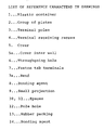
- the numeral 9 denotes a small projection on the bottom of the terminal receiving recess 4 for contacting part of the bend 7a of the Faston tab terminal so as to control the terminal 7; and 10 denotes space defined between said terminal receiving recess 4 and the bend 7a of said Faston tab terminal 7 to prevent the two from overall surface contact.
- the fixing of said plastic container 1 and cover 5 is effected by a bonding agent injected to the back side of the cover, this operation being performed by fitting the plastic container 1 having the plates group 2 received in advance in each cell chamber, from above over the cover 5 turned upside down, as shown in Fig. 4, and allowing the assembly to stand at about 60°C for 2 hours so as to cure the bonding agent. Thereafter, the front end portions of the Faston tab terminals projecting beyond the cover 5 are bent, as shown in Fig. 2.
- the terminals 7 are led to the outside of the battery which is above the surface of the bonding agent 8, that is, to the terminal receiving recess 4 and then the terminals are led to the lower surface of the cover 5, whereby the U-shaped connector portion and the terminal pole portion can be bonded together in a single operation without leakage of the bonding agent through the throughgoing holes 6.
- the bonding agent 8 enters the clearance between the Faston tab terminals 7 and the wall surface of the terminal receiving recess 4
- its upward crawling due to capillary action is interrupted by the space 10 defined by the small projection 9 between the bent 7a of the Faston tab terminal 7 and the terminal receiving recess 4.
- the upward crawling of the bonding agent 8 along the inner wall 5a of the cover 5 is interrupted by the space 11 provided thereabove.
- the spaces 10 and 11 are dimensioned to be greater than the capillary tube the bonding agent crawls up, it is prevented from further crawling up.
- the dimension of the space 10 defined by the small projection 9 between the bottom of the recess 4 and the bend 7a of the terminal is designed to be 1.0 mm
- the dimension of the clearance between the inner wall 5a and the terminal 7 is 2 mm
- the dimension of the space 11 is designed to be 4.0 mm.
- the terminal poles and plastic container of a lead storage battery can be liquid-tightly bonded together and the battery can be widely used as a power source for battery-using equipment without being restricted in its orientation when the lead storage battery is used.
Landscapes
- Chemical & Material Sciences (AREA)
- Chemical Kinetics & Catalysis (AREA)
- Electrochemistry (AREA)
- General Chemical & Material Sciences (AREA)
- Sealing Battery Cases Or Jackets (AREA)
- Connection Of Batteries Or Terminals (AREA)
Abstract
Description
- The present invention relates to a lead storage battery and particularly to improvements in a closed type lead storage battery, wherein the construction of bond between terminal poles and a cover for a plastic container is improved to provide a leakproof lead storage battery.
- In lead storage batteries using dilute sulfuric acid as the electrolyte, leakage of the electrolyte is the most detestable problem as it damages not only the battery itself but also the equipment which uses the battery.
- Such leak phenomenon takes place mainly (1) between the plastic container and the cover, (2) around the terminal poles of the battery, and (3) between the cells in the case of a monoblock battery. Thus, prevention of this leak phenomenon has been a long-standing problem in lead storage batteries, but no preventive method has been found which is simple and yet reliable.
- A conventional method of bonding the terminal poles to the cover will now'be described with reference to the drawings.
- As shown in Fig. 1, there is a step of filling a
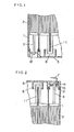
bonding agent 8 into a recess in the back of acover 5 in which aU-shaped connector 11 connecting cells is embedded, and into an annular recess in an outer peripheral portion bonded to aplastic container 1, and there is a subsequent step of invertedly fitting theplastic container 1 having inserted therein a group ofplates 2 over thecover 5 lying with its back side directed upward, and then bonding them together. At this time, aterminal pole 3 is not embedded in thebonding agent 8 but projects outward through apole hole 12 in thecover 5. After going through the step of curing said bonding agent, the battery is brought back to its normal position, as shown in Fig. 2. Then, arubber packing 13 is fitted on theterminal pole 3 so that abonding agent 14 for fixing theterminal pole 3 to thecover 5 may not fall down through thepole hole 12 onto theplates group 2 on the cell chamber side. The front end of the terminal pole is then soldered to a Fastontab terminal 7. After the step of filling thebonding agent 14 into the recess has been performed, thebonding agent 14 is cured to thereby bond the terminal pole and the cover together. - However, this method of producing batteries requires that the operation of bonding the terminal poles to the cover be performed in two stages, i.e., on the U-shaped connector portion connecting the cells and on the terminal pole portion; thus, not only is the number of steps increased but also it takes a long time for the bonding agent to cure. Therefore, there has been a disadvantage that too much time is taken for completion of the battery.
- The present invention is a lead storage battery wherein a terminal connected at one end thereof to a pole of a group of plates housed in a plastic container and projecting at the other end thereof upward through an end of a cover is partly embedded in a bonding agent which fixes said plastic container and said cover together, and defined between a terminal receiving recess formed in said plastic container and a terminal bend inserted in said terminal receiving recess and positioned below said bonding agent is a space which prevents the two from overall surface contact.
- According to the invention, at the same time as the plastic container and cover are bonded together, the terminal poles and cover are bonded together, so that the fixing of the terminal poles to the cover can be easily and economically effected and, moreover, the following effects can be attained.
- (1) A reduction in the number of steps required for bonding.
- (2) A reduction in the time taken for completion of the battery.
- (3) A reduction in cost.
-
- Fig. 1 is a sectional view of an electrolytic cell placed upside down in a conventional method of producing lead storage batteries;
- Fig. 2 is a sectional view showing the storage battery in normal position, with the terminal poles and cover fixed together by a bonding agent;
- Fig. 3 is an exploded perspective view of the plastic container and cover of a lead storage battery in an embodiment of the present invention; and
- Fig. 4 is a sectional view showing the arrangement of principal portions of a lead storage battery in an embodiment of the invention.
- Embodiments of the present invention will now be described with reference to the drawings.
- In Figs. 3 and 4, the
numeral 1 denotes a plastic container of ABS resin for a lead storage battery; 2 denotes a group of plates housed in each cell chamber of theplastic container 1; 3 denotes terminal poles for theplates group 2; 4 denotes a terminal receiving recess formed in part of theplastic container 1; 5 denotes a cover of the same material as the plastic container, mounted on saidplastic container 1; 7 denotes Faston tab terminals connected at one of their respective ends to thepoles 3 of theplates group 2 and projecting at the other ends upward through throughgoingholes 6 formed in an end of thecover 5, each having aU-shaped bend 7a inserted in therecess 4 of theplastic container 1; and 8 denotes an epoxy type bonding agent injected to the back side of thecover 5 for fixing theplastic container 1, thecover 5 and theterminals 7 together. Thenumeral 9 denotes a small projection on the bottom of the terminal receivingrecess 4 for contacting part of thebend 7a of the Faston tab terminal so as to control theterminal 7; and 10 denotes space defined between saidterminal receiving recess 4 and thebend 7a of said Fastontab terminal 7 to prevent the two from overall surface contact. - The fixing of said
plastic container 1 andcover 5 is effected by a bonding agent injected to the back side of the cover, this operation being performed by fitting theplastic container 1 having theplates group 2 received in advance in each cell chamber, from above over thecover 5 turned upside down, as shown in Fig. 4, and allowing the assembly to stand at about 60°C for 2 hours so as to cure the bonding agent. Thereafter, the front end portions of the Faston tab terminals projecting beyond thecover 5 are bent, as shown in Fig. 2. - In the above arrangement, the
terminals 7 are led to the outside of the battery which is above the surface of thebonding agent 8, that is, to theterminal receiving recess 4 and then the terminals are led to the lower surface of thecover 5, whereby the U-shaped connector portion and the terminal pole portion can be bonded together in a single operation without leakage of the bonding agent through thethroughgoing holes 6. In this connection, although thebonding agent 8 enters the clearance between the Fastontab terminals 7 and the wall surface of the terminal receivingrecess 4, its upward crawling due to capillary action is interrupted by thespace 10 defined by thesmall projection 9 between thebent 7a of the Fastontab terminal 7 and the terminal receivingrecess 4. - On the other hand, the upward crawling of the
bonding agent 8 along theinner wall 5a of thecover 5 is interrupted by thespace 11 provided thereabove. In addition, if thespaces - In the embodiment, since the clearance between the terminal receiving
recess 4 and theterminal 7 is 0.1 mm or less, the dimension of thespace 10 defined by thesmall projection 9 between the bottom of therecess 4 and thebend 7a of the terminal is designed to be 1.0 mm, and since the dimension of the clearance between theinner wall 5a and theterminal 7 is 2 mm, the dimension of thespace 11 is designed to be 4.0 mm. - As has been described so far, according to the present invention, the terminal poles and plastic container of a lead storage battery can be liquid-tightly bonded together and the battery can be widely used as a power source for battery-using equipment without being restricted in its orientation when the lead storage battery is used.
Claims (3)
Applications Claiming Priority (4)
| Application Number | Priority Date | Filing Date | Title |
|---|---|---|---|
| JP44492/83U | 1983-03-28 | ||
| JP44491/83U | 1983-03-28 | ||
| JP1983044491U JPS59149374U (en) | 1983-03-28 | 1983-03-28 | sealed lead acid battery |
| JP1983044492U JPS59149375U (en) | 1983-03-28 | 1983-03-28 | sealed lead acid battery |
Publications (3)
| Publication Number | Publication Date |
|---|---|
| EP0141855A1 true EP0141855A1 (en) | 1985-05-22 |
| EP0141855A4 EP0141855A4 (en) | 1985-09-18 |
| EP0141855B1 EP0141855B1 (en) | 1987-06-10 |
Family
ID=26384417
Family Applications (1)
| Application Number | Title | Priority Date | Filing Date |
|---|---|---|---|
| EP84901238A Expired EP0141855B1 (en) | 1983-03-28 | 1984-03-27 | Lead storage battery |
Country Status (4)
| Country | Link |
|---|---|
| US (1) | US4563402A (en) |
| EP (1) | EP0141855B1 (en) |
| DE (1) | DE3464180D1 (en) |
| WO (1) | WO1984003999A1 (en) |
Cited By (1)
| Publication number | Priority date | Publication date | Assignee | Title |
|---|---|---|---|---|
| EP0343333A1 (en) * | 1988-05-27 | 1989-11-29 | F.I.A.M.M. - FABBRICA ITALIANA ACCUMULATORI MOTOCARRI MONTECCHIO S.p.A. | Electrical connection of the terminal posts of a lead-acid battery to the exterior |
Families Citing this family (7)
| Publication number | Priority date | Publication date | Assignee | Title |
|---|---|---|---|---|
| JP3512816B2 (en) * | 1992-01-21 | 2004-03-31 | 松下電器産業株式会社 | Sealed lead-acid battery |
| WO1995023338A1 (en) * | 1994-02-28 | 1995-08-31 | Heraeus Sensor Gmbh | Sensor arrangement for a hot-film anemometer |
| US5985482A (en) * | 1998-04-28 | 1999-11-16 | Gnb Technologies, Inc. | Snap-on battery heat shield |
| CN2409616Y (en) * | 2000-01-21 | 2000-12-06 | 深圳市雄韬电源科技有限公司 | Sealed lead-acid accumulator |
| JP4459793B2 (en) * | 2004-11-29 | 2010-04-28 | 株式会社日立製作所 | Fuel cell end plate and fuel cell |
| DE102008009864A1 (en) * | 2008-02-19 | 2009-08-20 | FRÖTEK Vermögensverwaltung GmbH | Battery with sealing plug |
| WO2019102863A1 (en) * | 2017-11-21 | 2019-05-31 | 株式会社村田製作所 | Battery case |
Family Cites Families (5)
| Publication number | Priority date | Publication date | Assignee | Title |
|---|---|---|---|---|
| US3808073A (en) * | 1971-05-12 | 1974-04-30 | Irving L Navarre | Method of assembling plastic apparatus |
| JPS5456729U (en) * | 1977-09-28 | 1979-04-19 | ||
| JPS5488640U (en) * | 1977-12-07 | 1979-06-22 | ||
| GB2087133B (en) * | 1980-11-05 | 1984-07-18 | Chloride Group Ltd | Electric storage batteries |
| JPS57162253A (en) * | 1981-03-31 | 1982-10-06 | Shin Kobe Electric Mach Co Ltd | Assembly of lead battery |
-
1984
- 1984-03-27 WO PCT/JP1984/000139 patent/WO1984003999A1/en not_active Ceased
- 1984-03-27 US US06/680,339 patent/US4563402A/en not_active Expired - Lifetime
- 1984-03-27 EP EP84901238A patent/EP0141855B1/en not_active Expired
- 1984-03-27 DE DE8484901238T patent/DE3464180D1/en not_active Expired
Cited By (1)
| Publication number | Priority date | Publication date | Assignee | Title |
|---|---|---|---|---|
| EP0343333A1 (en) * | 1988-05-27 | 1989-11-29 | F.I.A.M.M. - FABBRICA ITALIANA ACCUMULATORI MOTOCARRI MONTECCHIO S.p.A. | Electrical connection of the terminal posts of a lead-acid battery to the exterior |
Also Published As
| Publication number | Publication date |
|---|---|
| DE3464180D1 (en) | 1987-07-16 |
| US4563402A (en) | 1986-01-07 |
| EP0141855A4 (en) | 1985-09-18 |
| EP0141855B1 (en) | 1987-06-10 |
| WO1984003999A1 (en) | 1984-10-11 |
Similar Documents
| Publication | Publication Date | Title |
|---|---|---|
| US7754378B2 (en) | Secondary battery with a sealing plate used to seal an electrolyte injection hole in a cap plate | |
| RU2331952C1 (en) | Composite cast lid and secondary battery with lid | |
| EP1715534A1 (en) | Battery pack of improved structure | |
| EP0141855B1 (en) | Lead storage battery | |
| JP2006519461A (en) | Lithium ion battery | |
| US3650841A (en) | Multiple cell galvanic battery | |
| US7682734B2 (en) | Rechargeable battery having pliable cell and manufacturing method thereof | |
| CN1327564C (en) | Rechargeable battery with integrated protection circuit | |
| US4482618A (en) | Aircraft battery | |
| CA1072192A (en) | Underwater connector | |
| EP2161769B1 (en) | Replaceable and versatile hermetically sealed lead-acid rechargeable cell | |
| JPH09237615A (en) | Sealed lead-acid battery | |
| CN120380848A (en) | Driving shell and pool robot | |
| JPH1079275A (en) | Housing for waterproof connector | |
| EP0552735B1 (en) | Sealed lead acid storage battery | |
| JPH0562426B2 (en) | ||
| CN201112436Y (en) | A soft pack battery | |
| US4233373A (en) | Cell casing and grommet therefore | |
| CN222953228U (en) | Battery and battery box | |
| KR100856833B1 (en) | Electric energy storage device and manufacturing method thereof | |
| CN220824161U (en) | Electrical box and electrical equipment | |
| JP3255196U (en) | Lid assembly for prismatic battery cells | |
| CN221687650U (en) | Battery cover assembly and battery | |
| JP3497919B2 (en) | Pressure cutoff sensor | |
| JPH06310168A (en) | Manufacturing method of sealed lead-acid battery |
Legal Events
| Date | Code | Title | Description |
|---|---|---|---|
| PUAI | Public reference made under article 153(3) epc to a published international application that has entered the european phase |
Free format text: ORIGINAL CODE: 0009012 |
|
| 17P | Request for examination filed |
Effective date: 19841127 |
|
| AK | Designated contracting states |
Designated state(s): DE FR GB |
|
| 17Q | First examination report despatched |
Effective date: 19860625 |
|
| GRAA | (expected) grant |
Free format text: ORIGINAL CODE: 0009210 |
|
| AK | Designated contracting states |
Kind code of ref document: B1 Designated state(s): DE FR GB |
|
| REF | Corresponds to: |
Ref document number: 3464180 Country of ref document: DE Date of ref document: 19870716 |
|
| ET | Fr: translation filed | ||
| PLBE | No opposition filed within time limit |
Free format text: ORIGINAL CODE: 0009261 |
|
| STAA | Information on the status of an ep patent application or granted ep patent |
Free format text: STATUS: NO OPPOSITION FILED WITHIN TIME LIMIT |
|
| 26N | No opposition filed | ||
| PGFP | Annual fee paid to national office [announced via postgrant information from national office to epo] |
Ref country code: FR Payment date: 19960315 Year of fee payment: 13 |
|
| PGFP | Annual fee paid to national office [announced via postgrant information from national office to epo] |
Ref country code: GB Payment date: 19960318 Year of fee payment: 13 |
|
| PGFP | Annual fee paid to national office [announced via postgrant information from national office to epo] |
Ref country code: DE Payment date: 19960328 Year of fee payment: 13 |
|
| PG25 | Lapsed in a contracting state [announced via postgrant information from national office to epo] |
Ref country code: GB Effective date: 19970327 |
|
| GBPC | Gb: european patent ceased through non-payment of renewal fee |
Effective date: 19970327 |
|
| PG25 | Lapsed in a contracting state [announced via postgrant information from national office to epo] |
Ref country code: FR Free format text: LAPSE BECAUSE OF NON-PAYMENT OF DUE FEES Effective date: 19971128 |
|
| PG25 | Lapsed in a contracting state [announced via postgrant information from national office to epo] |
Ref country code: DE Effective date: 19971202 |
|
| REG | Reference to a national code |
Ref country code: FR Ref legal event code: ST |