EP0141792A2 - A closure - Google Patents
A closure Download PDFInfo
- Publication number
- EP0141792A2 EP0141792A2 EP84850326A EP84850326A EP0141792A2 EP 0141792 A2 EP0141792 A2 EP 0141792A2 EP 84850326 A EP84850326 A EP 84850326A EP 84850326 A EP84850326 A EP 84850326A EP 0141792 A2 EP0141792 A2 EP 0141792A2
- Authority
- EP
- European Patent Office
- Prior art keywords
- closure
- marginal part
- closure according
- opening
- terized
- Prior art date
- Legal status (The legal status is an assumption and is not a legal conclusion. Google has not performed a legal analysis and makes no representation as to the accuracy of the status listed.)
- Granted
Links
Images
Classifications
-
- B—PERFORMING OPERATIONS; TRANSPORTING
- B65—CONVEYING; PACKING; STORING; HANDLING THIN OR FILAMENTARY MATERIAL
- B65D—CONTAINERS FOR STORAGE OR TRANSPORT OF ARTICLES OR MATERIALS, e.g. BAGS, BARRELS, BOTTLES, BOXES, CANS, CARTONS, CRATES, DRUMS, JARS, TANKS, HOPPERS, FORWARDING CONTAINERS; ACCESSORIES, CLOSURES, OR FITTINGS THEREFOR; PACKAGING ELEMENTS; PACKAGES
- B65D3/00—Rigid or semi-rigid containers having bodies or peripheral walls of curved or partially-curved cross-section made by winding or bending paper without folding along defined lines
- B65D3/10—Rigid or semi-rigid containers having bodies or peripheral walls of curved or partially-curved cross-section made by winding or bending paper without folding along defined lines characterised by form of integral or permanently secured end closure
- B65D3/12—Flanged discs permanently secured, e.g. by adhesives or by heat-sealing
-
- B—PERFORMING OPERATIONS; TRANSPORTING
- B65—CONVEYING; PACKING; STORING; HANDLING THIN OR FILAMENTARY MATERIAL
- B65D—CONTAINERS FOR STORAGE OR TRANSPORT OF ARTICLES OR MATERIALS, e.g. BAGS, BARRELS, BOTTLES, BOXES, CANS, CARTONS, CRATES, DRUMS, JARS, TANKS, HOPPERS, FORWARDING CONTAINERS; ACCESSORIES, CLOSURES, OR FITTINGS THEREFOR; PACKAGING ELEMENTS; PACKAGES
- B65D17/00—Rigid or semi-rigid containers specially constructed to be opened by cutting or piercing, or by tearing of frangible members or portions
- B65D17/06—Integral, or permanently secured, end or side closures
- B65D17/12—Closures secured by soldering, welding, or otherwise uniting opposed surfaces
Definitions
- the present invention relates to a closure for a packaging container, primarily for pressure creating or pressurized filling goods, for instance carbonated drinks.
- a closure for a packaging container, primarily for pressure creating or pressurized filling goods, for instance carbonated drinks.
- the closure is useful also in general for containers having relatively thin walls.
- the closure is of a heat sealable type providing an adequate sealing pressure in the sealing area.
- the problem behind the invention is to provide a closure having strain resisting sealing characteristics and an inherent controllable deformation resistance against internal pressure as well as handling.
- the problem is also to provide means allowing expansion, created by pressure, of the volume of the package such that a volume in excess to the nominal filling volume may be assumed.
- a most important sub-problem is to provide a closure allowing sealing with an acceptable counter-pressure, meaning the provision of a sufficient sealing pressure in the sealing area.
- the invention in general provides a closure for a packaging container comprising at least one panel of a relatively thin and flexible material for substantially covering an opening in the packaging container, and a marginal part surrounding the panel and attachable to the edge of the opening.
- the closure is characterized in that the marginal part comprises a sealing area having a fold formed in the panel and exposed to the internal region of the package, said sealing area at least partially consisting of the said flexible material and having a sealing strength in the interval zero to less than the sealing strength of the marginal part against the edge.
- the closure forms the end piece of a sleeve shaped container casing
- the sealing area comprises a fold having radially inner and outer rims and extending circumferentially around the panel.
- the radially outer rim of the fold is integral with a lip of the marginal part that is attachable to the casing.
- the radially outer rim forms said lip.
- the lip comprises a double layer of the flexible material.
- the layers of the lip preferably are sealed against each other.
- the sealing strength between the layers of the lip is higher than the sealing strength of the fold.
- this layer preferably comprises at least the lower portion of the rim and a skirt folded around the rim.
- the extension of the skirt preferably is such that at least one edge is hidden behind the rim and/or in the wall of the packaging container.
- the marginal part with advantage comprises a conical region acting as an entering part.
- the marginal part and/or the panel preferably also comprises a material suitable for induction sealing or high frequency welding or a combination thereof, at least in the sealing area.
- the reference numeral 10 generally relates to a container closure shown in a partial section view and comprising a lid panel 11 and a marginal part 12.
- the closure 10 is manufactured from a relative thin flexible material, for instance a laminate comprising an aluminium foil having a thickness in the interval 10 to 200 ⁇ m and having a coating of a thermoplastic material, preferably a polyolefine, on one or both sides thereof.
- a relative thin flexible material for instance a laminate comprising an aluminium foil having a thickness in the interval 10 to 200 ⁇ m and having a coating of a thermoplastic material, preferably a polyolefine, on one or both sides thereof.
- Other type of material/material combinations are of course possible, for instance plastic laminates/plastic film having a suitable additive for giving the required tightness degree and/or for allowing a specific sealing method.
- a sealing area comprising a fold 13 extending around the panel 11 is formed in the end closure and exposed to the internal region of the package, which here merely has been shown as a portion of a sleeve wall 14.
- the fold is formed by folding the margin of the blank forming the closure 10.
- the fold has an outer rim 15, which is this case alone forms a lip for sealing against the sleeve wall.
- the seal 16 between the rim and the sleeve is formed with a sufficient sealing pressure for obtaining an acceptable sealing. This pressure is obtained in that a counter-pressure is created by means of a support 17 which is displaceable in the directions of the double arrow 18 and for instance expandable in the directions of the double arrow 18' and which co-operates with a stationary support 19.
- the sealing technique used may for instance comprise induction welding or high frequency welding, and in this case the material of the end closure 10, at least in the welding area comprises an additive well suited for the actual welding technique.
- the end closure generally is laminated with a metal foil (not explicitely shown in Figures 1 to 5) along the entire surface thereof.
- the seal 16 preferably extends along the entire height of the rim 15 and continously around the sleeve 14.
- a lacquer layer 20 In order to protect the free edge of the rim, the cut edge, a lacquer layer 20, alternatively a tape or other protective means is arranged along the edge facing the internal region of the package.
- the fold 1.3 which is exposed to the internal region of the package, has a seal 22 of so called peelable type.
- the seal 22 is thus weaker than the seal 16.
- the seal 22 will break (if such a seal exists, i.e. a seal having a strength higher than zero).
- the flexible end closure 10 (cover panel 11) then assumes its natural shape according to the broken lines 23 in Figure 1. Due to the increase of volume the pressure decreases inside the container.
- the seal is protected by this construction, meaning that the risk for leakage and destruction of the contents of the package is reduced at the same time as the fold construction, in the manner mentioned, allows the creation of an acceptable sealing pressure.
- a lip 15 comprising double material layers 15' and 15".
- the layer 15' forms a skirt which is folded and sealed against the rim 15" in order to reinforce the end closure.
- the seal 15"' preferably is of the same strength as the seal 16 and has an extension in the height direction for instance equal to the height of the rim 15". The seal may also be accomplished dot-wise, alternatively along a certain part of the height of the rim.
- the fold 13 has a peelable seal 22, which at a strain exceeding the maximum load allows resetting of lid panel 11 to the natural position 23 thereof.
- edge part 12 is placed in a position below the top edge of the sleeve 14. Such placement implies that the lid panel 11, in the natural position 23 thereof, is protected by the sleeve 14 and/or the skirt 15'.
- FIG 4 there is shown a version of an end closure where the skirt 15' is shortened and the upper portion of the rim 15" of the marginal part 12 is sealed against the sleeve 14. This seal together with the seal 16 forms the actual sealing of the end closure 10. In the same manner as previously there is a peelable seal 22 in the fold 13 exposed to the internal region of the package.
- FIG 5 there is shown a conical marginal part 12 for facilitating the entering operation.
- the rim 15 of the marginal part may be formed from or covered by a banderol 25 according to Figure 6.
- a banderol punched out to a trapezoid shape, almost provides an essentially smooth sealing area.
- end closures in the embodiments shown have been manufactured from a flexible, foldable material it is realized that other processing techniques, for instance injection moulding, may be used as an alternative for manufacturing of certain parts, for instance the marginal part, of the end closure.
- FIG 7 there is shown a version where the lid panel 11 comprises a relatively thick material and for instance is injection moulded and thereafter laminated by an aluminium foil 11' or corresponding.
- the idea is to provide a double layer 12 which may be pressed together and pressed against the walls of the sleeve or the opening edge against which the closure should be placed.
- the pressing together may for instance be accomplished by pressing the panel 11 axially inwards the container at the same time as the rim 15 is prevented from moving into the sleeve.
- Such a controlled pressing operation may be obtained by overdimensioning the double layer relative the opening, at least in certain areas of the double layer, for instance by forming said layer with a truncated conical shape as in Figure 8.
- Figure 9 shows the effect of the pressing together pressure - between the layers and against the sleeve - after folding. Frequently, the "void space" will not occur, but in Figure 9 it has been indicated for illustration purposes as a result obtainable by a controlled application of pressure in the welding area.
- FIG 10 there is shown a pressure resistant closure obtained by over-dimensioning the foil/sealing label 11' relative the opening in the sleeve 14.
- the strain is transferred by the relatively stiff rim 15, meaning an advantageous "line load” (along a line in the height direction) in the welding area (contrary to a strain along a peripheral line).
Abstract
Description
- The present invention relates to a closure for a packaging container, primarily for pressure creating or pressurized filling goods, for instance carbonated drinks. With advantage the closure is useful also in general for containers having relatively thin walls. Additionally, the closure is of a heat sealable type providing an adequate sealing pressure in the sealing area.
- The problem behind the invention is to provide a closure having strain resisting sealing characteristics and an inherent controllable deformation resistance against internal pressure as well as handling.
- The problem is also to provide means allowing expansion, created by pressure, of the volume of the package such that a volume in excess to the nominal filling volume may be assumed.
- A most important sub-problem is to provide a closure allowing sealing with an acceptable counter-pressure, meaning the provision of a sufficient sealing pressure in the sealing area.
- In for instance the European patent specification No. 0029039 there is described an end closure for a sleeve shaped packaging container manufactured from a relatively thin material. As such, the end closure reinforces the packaging construction, but for the rest there is no solution to the main problem or the sub-problems of the present invention.
- In order to eliminate such lack the invention in general provides a closure for a packaging container comprising at least one panel of a relatively thin and flexible material for substantially covering an opening in the packaging container, and a marginal part surrounding the panel and attachable to the edge of the opening. The closure is characterized in that the marginal part comprises a sealing area having a fold formed in the panel and exposed to the internal region of the package, said sealing area at least partially consisting of the said flexible material and having a sealing strength in the interval zero to less than the sealing strength of the marginal part against the edge.
- In one embodiment the closure forms the end piece of a sleeve shaped container casing, and the sealing area comprises a fold having radially inner and outer rims and extending circumferentially around the panel. The radially outer rim of the fold is integral with a lip of the marginal part that is attachable to the casing.
- In said embodiment preferably the radially outer rim forms said lip.
- In another embodiment the lip comprises a double layer of the flexible material.
- In a manner known per se, in order to increase the deformation resistance, the layers of the lip preferably are sealed against each other.
- In the actual embodiment the sealing strength between the layers of the lip is higher than the sealing strength of the fold.
- In order to "hide" the "cut edge" of the double layer, this layer preferably comprises at least the lower portion of the rim and a skirt folded around the rim.
- The extension of the skirt preferably is such that at least one edge is hidden behind the rim and/or in the wall of the packaging container.
- In either one of said embodiments the marginal part with advantage comprises a conical region acting as an entering part.
- The marginal part and/or the panel preferably also comprises a material suitable for induction sealing or high frequency welding or a combination thereof, at least in the sealing area.
-
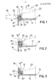
- Figure 1 in a partial section view shows a first embodiment of an end closure of a container together with a portion of a container wall,
- Figure 2 in a partial section view shows another embodiment of an end closure of a container together with a portion of a container wall,
- Figure 3 in a partial section shows a third embodiment of an end closure of a container together with a portion of the wall of the container,
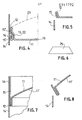
- Figure 4 in a partial section view shows a fourth embodiment of an end closure of a container together with a portion of a container wall,
- Figure 5 in a partial section view shows a container closure according to the principles of the invention provided with a conical entering portion,
- Figure 6 shows a trapezoid strip which is to be formed into a truncated conical funnel for forming an essentially smooth abutment surface against the inside of the packaging container,
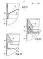
- Figure 7 shows an injection moulded closure having a foil laminated thereto,
- Figure 8 shows a closure having a conical double rim,
- Figure 9 shows the closure in a sealed state,
- Figure 10 shows an injection moulded closure having an overdimensioned sealing label, and
- Figure 11 shows an injection moulded closure consisting of two parts, also having an overdimensioned sealing label.
- In Figure 1 the
reference numeral 10 generally relates to a container closure shown in a partial section view and comprising alid panel 11 and amarginal part 12. In the embodiment that has been shown theclosure 10 is manufactured from a relative thin flexible material, for instance a laminate comprising an aluminium foil having a thickness in theinterval 10 to 200 µm and having a coating of a thermoplastic material, preferably a polyolefine, on one or both sides thereof. Other type of material/material combinations are of course possible, for instance plastic laminates/plastic film having a suitable additive for giving the required tightness degree and/or for allowing a specific sealing method. - A sealing area comprising a
fold 13 extending around thepanel 11 is formed in the end closure and exposed to the internal region of the package, which here merely has been shown as a portion of asleeve wall 14. In this case the fold is formed by folding the margin of the blank forming theclosure 10. The fold has anouter rim 15, which is this case alone forms a lip for sealing against the sleeve wall. Theseal 16 between the rim and the sleeve is formed with a sufficient sealing pressure for obtaining an acceptable sealing. This pressure is obtained in that a counter-pressure is created by means of asupport 17 which is displaceable in the directions of thedouble arrow 18 and for instance expandable in the directions of the double arrow 18' and which co-operates with astationary support 19. The sealing technique used may for instance comprise induction welding or high frequency welding, and in this case the material of theend closure 10, at least in the welding area comprises an additive well suited for the actual welding technique. For rational reasons the end closure generally is laminated with a metal foil (not explicitely shown in Figures 1 to 5) along the entire surface thereof. In the embodiment according to Figure 1 theseal 16 preferably extends along the entire height of therim 15 and continously around thesleeve 14. - In order to protect the free edge of the rim, the cut edge, a
lacquer layer 20, alternatively a tape or other protective means is arranged along the edge facing the internal region of the package. - Alternatively, it is possible to press the edge into the material of the
casing 14, as shown by thereference numeral 21 in Figure 1. - The fold 1.3, which is exposed to the internal region of the package, has a
seal 22 of so called peelable type. Theseal 22 is thus weaker than theseal 16. - If for some reason, for instance due to a pressure increase originating from the filling goods, the internal pressure increases within the container, the
seal 22 will break (if such a seal exists, i.e. a seal having a strength higher than zero). The flexible end closure 10 (cover panel 11) then assumes its natural shape according to thebroken lines 23 in Figure 1. Due to the increase of volume the pressure decreases inside the container. The seal is protected by this construction, meaning that the risk for leakage and destruction of the contents of the package is reduced at the same time as the fold construction, in the manner mentioned, allows the creation of an acceptable sealing pressure. - In Figure 2 there is shown a
lip 15 comprisingdouble material layers 15' and 15". The layer 15' forms a skirt which is folded and sealed against therim 15" in order to reinforce the end closure. Theseal 15"' preferably is of the same strength as theseal 16 and has an extension in the height direction for instance equal to the height of therim 15". The seal may also be accomplished dot-wise, alternatively along a certain part of the height of the rim. In the same manner as previously, thefold 13 has apeelable seal 22, which at a strain exceeding the maximum load allows resetting oflid panel 11 to thenatural position 23 thereof. - The free edge of the skirt 15' is turned away from the internal region of the container and in Figure 1 the skirt is located at the same level as the upper edge of the
sleeve 14 and the uppermost portion of thelip 12. - An extension of the skirt 15' according to the
broken line 24 is also possible. - I Figure 3 the
edge part 12 is placed in a position below the top edge of thesleeve 14. Such placement implies that thelid panel 11, in thenatural position 23 thereof, is protected by thesleeve 14 and/or the skirt 15'. - In Figure 4 there is shown a version of an end closure where the skirt 15' is shortened and the upper portion of the
rim 15" of themarginal part 12 is sealed against thesleeve 14. This seal together with theseal 16 forms the actual sealing of theend closure 10. In the same manner as previously there is apeelable seal 22 in thefold 13 exposed to the internal region of the package. - In Figure 5 there is shown a conical
marginal part 12 for facilitating the entering operation. Therim 15 of the marginal part may be formed from or covered by abanderol 25 according to Figure 6. Such a banderol, punched out to a trapezoid shape, almost provides an essentially smooth sealing area. - Although the end closures in the embodiments shown have been manufactured from a flexible, foldable material it is realized that other processing techniques, for instance injection moulding, may be used as an alternative for manufacturing of certain parts, for instance the marginal part, of the end closure.
- In Figure 7 there is shown a version where the
lid panel 11 comprises a relatively thick material and for instance is injection moulded and thereafter laminated by analuminium foil 11' or corresponding. The idea is to provide adouble layer 12 which may be pressed together and pressed against the walls of the sleeve or the opening edge against which the closure should be placed. The pressing together may for instance be accomplished by pressing thepanel 11 axially inwards the container at the same time as therim 15 is prevented from moving into the sleeve. - Such a controlled pressing operation may be obtained by overdimensioning the double layer relative the opening, at least in certain areas of the double layer, for instance by forming said layer with a truncated conical shape as in Figure 8.
- Figure 9 shows the effect of the pressing together pressure - between the layers and against the sleeve - after folding. Frequently, the "void space" will not occur, but in Figure 9 it has been indicated for illustration purposes as a result obtainable by a controlled application of pressure in the welding area.
- In Figure 10 there is shown a pressure resistant closure obtained by over-dimensioning the foil/
sealing label 11' relative the opening in thesleeve 14. When pressure occurs or strain occurs in theweld 16, the strain is transferred by the relativelystiff rim 15, meaning an advantageous "line load" (along a line in the height direction) in the welding area (contrary to a strain along a peripheral line). - Still increased strain resistance is possible by the two-part closure in Figure 11 comprising a
separate panel 11 and a separatemarginal part 12.
Claims (16)
Priority Applications (1)
| Application Number | Priority Date | Filing Date | Title |
|---|---|---|---|
| AT84850326T ATE42523T1 (en) | 1983-11-07 | 1984-10-25 | CLOSURE. |
Applications Claiming Priority (2)
| Application Number | Priority Date | Filing Date | Title |
|---|---|---|---|
| SE8306087A SE444423B (en) | 1983-11-07 | 1983-11-07 | CLOSING TO PACKAGING CONTAINER |
| SE8306087 | 1983-11-07 |
Publications (3)
| Publication Number | Publication Date |
|---|---|
| EP0141792A2 true EP0141792A2 (en) | 1985-05-15 |
| EP0141792A3 EP0141792A3 (en) | 1986-09-17 |
| EP0141792B1 EP0141792B1 (en) | 1989-04-26 |
Family
ID=20353196
Family Applications (1)
| Application Number | Title | Priority Date | Filing Date |
|---|---|---|---|
| EP84850326A Expired EP0141792B1 (en) | 1983-11-07 | 1984-10-25 | A closure |
Country Status (4)
| Country | Link |
|---|---|
| EP (1) | EP0141792B1 (en) |
| AT (1) | ATE42523T1 (en) |
| DE (1) | DE3477917D1 (en) |
| SE (1) | SE444423B (en) |
Cited By (2)
| Publication number | Priority date | Publication date | Assignee | Title |
|---|---|---|---|---|
| EP1174354A1 (en) * | 2000-07-19 | 2002-01-23 | Franz Delbrouck GmbH | Transport container |
| WO2019068486A1 (en) * | 2017-10-04 | 2019-04-11 | Tetra Laval Holdings & Finance S.A. | Packaging container |
Families Citing this family (1)
| Publication number | Priority date | Publication date | Assignee | Title |
|---|---|---|---|---|
| US9005605B2 (en) | 2010-08-19 | 2015-04-14 | Allergan, Inc. | Compositions and soft tissue replacement methods |
Citations (1)
| Publication number | Priority date | Publication date | Assignee | Title |
|---|---|---|---|---|
| WO1980002544A1 (en) | 1979-05-23 | 1980-11-27 | Scal Gp Condit Aluminium | Flexible wall container for pressurized products and process for manufacturing such container |
Family Cites Families (3)
| Publication number | Priority date | Publication date | Assignee | Title |
|---|---|---|---|---|
| DE215245C (en) * | 1908-08-29 | 1909-10-26 | ||
| US2085458A (en) * | 1934-11-19 | 1937-06-29 | Clarence H Walker | Box |
| DE3305144A1 (en) * | 1983-02-15 | 1984-08-16 | Hoechst Ag, 6230 Frankfurt | INNER PRESSURE-RESISTANT PACKING MADE OF FLEXIBLE MATERIAL FOR FILLING MATERIAL, PREFERRED LIQUIDS, METHOD FOR THE PRODUCTION OF A FILLED PACKAGING AND USE OF THE PACKING |
-
1983
- 1983-11-07 SE SE8306087A patent/SE444423B/en not_active IP Right Cessation
-
1984
- 1984-10-25 AT AT84850326T patent/ATE42523T1/en not_active IP Right Cessation
- 1984-10-25 EP EP84850326A patent/EP0141792B1/en not_active Expired
- 1984-10-25 DE DE8484850326T patent/DE3477917D1/en not_active Expired
Patent Citations (2)
| Publication number | Priority date | Publication date | Assignee | Title |
|---|---|---|---|---|
| WO1980002544A1 (en) | 1979-05-23 | 1980-11-27 | Scal Gp Condit Aluminium | Flexible wall container for pressurized products and process for manufacturing such container |
| EP0029039A1 (en) | 1979-05-23 | 1981-05-27 | Scal Gp Condit Aluminium | Flexible wall container for pressurized products. |
Cited By (3)
| Publication number | Priority date | Publication date | Assignee | Title |
|---|---|---|---|---|
| EP1174354A1 (en) * | 2000-07-19 | 2002-01-23 | Franz Delbrouck GmbH | Transport container |
| WO2019068486A1 (en) * | 2017-10-04 | 2019-04-11 | Tetra Laval Holdings & Finance S.A. | Packaging container |
| EP3466824A3 (en) * | 2017-10-04 | 2019-04-17 | Tetra Laval Holdings & Finance S.A. | Packaging container |
Also Published As
| Publication number | Publication date |
|---|---|
| SE8306087L (en) | 1985-05-08 |
| EP0141792B1 (en) | 1989-04-26 |
| SE444423B (en) | 1986-04-14 |
| DE3477917D1 (en) | 1989-06-01 |
| EP0141792A3 (en) | 1986-09-17 |
| SE8306087D0 (en) | 1983-11-07 |
| ATE42523T1 (en) | 1989-05-15 |
Similar Documents
| Publication | Publication Date | Title |
|---|---|---|
| FI89782B (en) | LOCK FOER TLLSLUTNING AV OEPPNINGEN I EN BURK | |
| US4986465A (en) | Opening arrangement on a packing container | |
| US5752614A (en) | Easy-opening closure for hermetic sealing a retortable container | |
| CA2158016C (en) | Easy-opening composite closure | |
| US5125529A (en) | Thermoplastic container opened by partially peeling back a multi-layered top which has been heat-sealed to its edge, and film for multi-layer tops | |
| US5069355A (en) | Easy-opening composite closure for hermetic sealing of a packaging container by double seaming | |
| US6401967B1 (en) | Frozen dessert container | |
| EP1081051B1 (en) | Easy-open composite container with a membrane-type closure | |
| US3805993A (en) | Closure for metal container | |
| US5002223A (en) | Easy-open package with outwardly projecting open tab | |
| EP0185516B1 (en) | Hermetic sealed container | |
| US20060191940A1 (en) | Sealing surfaces for container end panels | |
| US3833144A (en) | Two position pull tab easy-open container component | |
| US4254891A (en) | Stackable cover member for a container | |
| CN111295343A (en) | Resealable closure with patterned adhesive | |
| US4632298A (en) | Packing container | |
| EP0483971A1 (en) | Multi-piece flat top container | |
| GB2052455A (en) | Container lid, and package and packaging method using same | |
| US3863830A (en) | Liquid and gas sealing cardboard package | |
| GB2123786A (en) | Covered containers | |
| EP0141792A2 (en) | A closure | |
| US4712706A (en) | Easy open type can | |
| JPH04267729A (en) | Gable-top container and sheet material blank for forming thereof | |
| US3151765A (en) | Re-closable hermetically sealed container | |
| GB1571938A (en) | Patch top container and closure assembly and method of making the same |
Legal Events
| Date | Code | Title | Description |
|---|---|---|---|
| PUAI | Public reference made under article 153(3) epc to a published international application that has entered the european phase |
Free format text: ORIGINAL CODE: 0009012 |
|
| AK | Designated contracting states |
Designated state(s): AT BE CH DE FR GB IT LI LU NL |
|
| PUAL | Search report despatched |
Free format text: ORIGINAL CODE: 0009013 |
|
| AK | Designated contracting states |
Kind code of ref document: A3 Designated state(s): AT BE CH DE FR GB IT LI LU NL |
|
| 17P | Request for examination filed |
Effective date: 19870224 |
|
| 17Q | First examination report despatched |
Effective date: 19871202 |
|
| GRAA | (expected) grant |
Free format text: ORIGINAL CODE: 0009210 |
|
| AK | Designated contracting states |
Kind code of ref document: B1 Designated state(s): AT BE CH DE FR GB IT LI LU NL |
|
| ITF | It: translation for a ep patent filed |
Owner name: BARZANO' E ZANARDO ROMA S.P.A. |
|
| PG25 | Lapsed in a contracting state [announced via postgrant information from national office to epo] |
Ref country code: NL Effective date: 19890426 Ref country code: LI Effective date: 19890426 Ref country code: CH Effective date: 19890426 Ref country code: BE Effective date: 19890426 Ref country code: AT Effective date: 19890426 |
|
| REF | Corresponds to: |
Ref document number: 42523 Country of ref document: AT Date of ref document: 19890515 Kind code of ref document: T |
|
| REF | Corresponds to: |
Ref document number: 3477917 Country of ref document: DE Date of ref document: 19890601 |
|
| ET | Fr: translation filed | ||
| REG | Reference to a national code |
Ref country code: CH Ref legal event code: PL |
|
| NLV1 | Nl: lapsed or annulled due to failure to fulfill the requirements of art. 29p and 29m of the patents act | ||
| PG25 | Lapsed in a contracting state [announced via postgrant information from national office to epo] |
Ref country code: LU Free format text: LAPSE BECAUSE OF NON-PAYMENT OF DUE FEES Effective date: 19891031 |
|
| PLBE | No opposition filed within time limit |
Free format text: ORIGINAL CODE: 0009261 |
|
| STAA | Information on the status of an ep patent application or granted ep patent |
Free format text: STATUS: NO OPPOSITION FILED WITHIN TIME LIMIT |
|
| 26N | No opposition filed | ||
| PGFP | Annual fee paid to national office [announced via postgrant information from national office to epo] |
Ref country code: FR Payment date: 19930901 Year of fee payment: 10 |
|
| PGFP | Annual fee paid to national office [announced via postgrant information from national office to epo] |
Ref country code: GB Payment date: 19930927 Year of fee payment: 10 |
|
| ITTA | It: last paid annual fee | ||
| PGFP | Annual fee paid to national office [announced via postgrant information from national office to epo] |
Ref country code: DE Payment date: 19931124 Year of fee payment: 10 |
|
| PG25 | Lapsed in a contracting state [announced via postgrant information from national office to epo] |
Ref country code: GB Effective date: 19941025 |
|
| GBPC | Gb: european patent ceased through non-payment of renewal fee |
Effective date: 19941025 |
|
| PG25 | Lapsed in a contracting state [announced via postgrant information from national office to epo] |
Ref country code: FR Effective date: 19950630 |
|
| PG25 | Lapsed in a contracting state [announced via postgrant information from national office to epo] |
Ref country code: DE Effective date: 19950701 |
|
| REG | Reference to a national code |
Ref country code: FR Ref legal event code: ST |