EP0141626A2 - Power steering control apparatus - Google Patents
Power steering control apparatus Download PDFInfo
- Publication number
- EP0141626A2 EP0141626A2 EP84307361A EP84307361A EP0141626A2 EP 0141626 A2 EP0141626 A2 EP 0141626A2 EP 84307361 A EP84307361 A EP 84307361A EP 84307361 A EP84307361 A EP 84307361A EP 0141626 A2 EP0141626 A2 EP 0141626A2
- Authority
- EP
- European Patent Office
- Prior art keywords
- circuit
- signal
- voltage
- control apparatus
- solenoid
- Prior art date
- Legal status (The legal status is an assumption and is not a legal conclusion. Google has not performed a legal analysis and makes no representation as to the accuracy of the status listed.)
- Granted
Links
Images

Classifications
-
- B—PERFORMING OPERATIONS; TRANSPORTING
- B62—LAND VEHICLES FOR TRAVELLING OTHERWISE THAN ON RAILS
- B62D—MOTOR VEHICLES; TRAILERS
- B62D5/00—Power-assisted or power-driven steering
- B62D5/06—Power-assisted or power-driven steering fluid, i.e. using a pressurised fluid for most or all the force required for steering a vehicle
-
- B—PERFORMING OPERATIONS; TRANSPORTING
- B62—LAND VEHICLES FOR TRAVELLING OTHERWISE THAN ON RAILS
- B62D—MOTOR VEHICLES; TRAILERS
- B62D6/00—Arrangements for automatically controlling steering depending on driving conditions sensed and responded to, e.g. control circuits
- B62D6/008—Control of feed-back to the steering input member, e.g. simulating road feel in steer-by-wire applications
-
- B—PERFORMING OPERATIONS; TRANSPORTING
- B62—LAND VEHICLES FOR TRAVELLING OTHERWISE THAN ON RAILS
- B62D—MOTOR VEHICLES; TRAILERS
- B62D6/00—Arrangements for automatically controlling steering depending on driving conditions sensed and responded to, e.g. control circuits
- B62D6/02—Arrangements for automatically controlling steering depending on driving conditions sensed and responded to, e.g. control circuits responsive only to vehicle speed
Definitions
- This invention relates to a power steering control apparatus used for an automobile etc., and in particular to a power steering control apparatus for improving the safety during a high speed running upon the occurrence of an abnormal condition at least in a current feedback loop and capable of preventing a secondary failure.
- a power steering control apparatus for an automobile reduce (lighten) the manual steering power required in proportion to the steering load while increasing the manual steering power required in proportion to the car speed so as to make the steering operation safe during a high speed running.
- Japanese Patent Application Laid-open No. 58-188751 discloses a protection circuit in which a chopper circuit for driving a power steering motor is disconnected in the event that an input/output signal line for an angular sensor serving for the reciprocal rotation of a power steering motor is broken.
- Japanese Patent Application Laid-open No. 56-146473 discloses a power steering control apparatus in which an output power transistor is prevented from being destroyed, overheated, or burned even when a linear solenoid as a load is shorted and the wiring is grounded, while a steering condition is maintained at a low speed.
- Japanese Patent Application Laid-open No. 57-178972 discloses a speed sensitive power steering apparatus in which when a change gear selects a gear position other than that of the first gear and the reverse gear, the absence of a car speed signal is detected for a failsafe operation.
- the present invention has been made to solve the above conventional problem.
- the present invention broadly resides in a power steering control apparatus comprising a car speed sensor, a power source, an electric control circuit connected to the car speed sensor and the power source, and a proportional solenoid, responsive to the output of the electric control circuit, for providing a steering reaction oil pressure;
- the electric control circuit including: first means for producing a command signal in inverse proportion to the output of the car speed sensor; second means for detecting a current signal flowing through the proportional solenoid; third means for comparing the command signal with the current signal as a feedback signal to develop an error signal therebetween; fourth means for developing from the error signal a driving signal for the proportional solenoid; fifth means, responsive to the error signal, for detecting a predetermined abnormal condition and holding the abnormal condition; and, sixth means, responsive to the output of the fifth means, for passing the electrical energy from the power source to the fourth means in the normal condition while interrupting the electrical energy to the fourth means in the predetermined abnormal condition.
- the fifth means comprises an integration portion for integrating the error signal from the error amplification circuit, a comparing portion for comparing the integrated voltage of the integration portion with a reference voltage corresponding to the predetermined abnormal detective signal and for providing as an output therefrom a signal indicating the abnormal condition, and a holding portion for holding the integrated voltage of the integration portion in the abnormal condition.
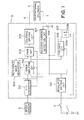
- FIG. 1 one preferred embodiment of a power steering control apparatus according to this invention is shown. Only the essential elements are shown.
- the positive terminal of a DC battery 1 mounted on a car is connected to one terminal of a key switch 2 and the negative terminal thereof is grounded.
- the other terminal of the key switch 2 and a car speed sensor 3 are electrically connected to a proportional solenoid 4 through an electric control circuit 5.
- the speed sensor 3 may be of the type which uses pulses of a speed meter of a lead-switch or a transistor type.
- the proportional solenoid 4 controls a hydraulic valve (not shown), for providing a reaction oil pressure for a steering mechanism, in proportion to the level of its conduction current.
- the electric control circuit 5 receives as an input an electrical power from the battery 1 through the key switch 2, receives as an input a speed signal from the sensor 3, and consequently provides as an output therefrom a current signal in inverse proportion to the car speed, thereby to drive the proportional solenoid 4.
- the electrical control circuit 5 is composed of a frequency/voltage (F/V) converter 501, an error amplifying circuit 502, a reference wave generator 503, a pulse width modulation (PWM) circuit 504, a proportional solenoid driving circuit 505, a shunt resistor 506, a solenoid current detection circuit 507, a failsafe circuit 508, a protection relay 509 including a coil 509a and a normally closed contact 509b, and a regulated voltage circuit 510.
- F/V frequency/voltage
- PWM pulse width modulation
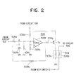
- a resistor 508a is connected to the output terminal of the error amplifying circuit 502 and the other terminal thereof is connected to a capacitor 508b, the combination of the resistor 508a and the capacitor 508b forming a delay (integration) circuit.
- A-ross the capacitor 508b is connected a resistor 508c which serves as a discharging resistor for the capacitor 508b after the integration has been completed.
- the junction of the resistor 508a, the capacitor 508b, and the resistor 508c is connected to the inverting input of a comparator 508f the non-inverting input of which is connected to the junction of voltage dividing resistors 508d and 508e.
- the other ends of the capacitor 508b, the resistor 508c, and the resistor 508e are grounded.
- the non-inverting input of the comparator 508f is set to a reference voltage determined by the dividing resistors 508d and 508e.
- the output of the comparator 508f is connected through a resistor 508g to the base of a transistor Tr the collector of which is connected through the relay coil 509a of the protection relay 509 to ground.
- the junction of the collector of the transistor Tr and the coil 509a is connected through a resistor 508h to the junction of the resistor 508a and the capacitor 508b to form a holding circuit.
- the F/V converter 501 converts the frequency of pulses from the sensor 3 into a reverse-proportional voltage.
- the error amplifying circuit 502 compares the output voltage, as a reference, of the F/V converter 501 which corresponds to a car speed and the output voltage of the detection circuit 507 which corresponds to the current flowing through the proportional solenoid 4, and amplifies the error.
- the oscillation circuit 503 generates a triangular wave signal or a saw tooth wave signal at a reference frequency (500-1000 Hz) which is used to develop a pulse width modulated-wave voltage from the PWM circuit 504.
- This PWM circuit 504 compares the output voltages of the error amplifying circuit 502 and the reference wave generator 503, and modulates the output waveform of the reference wave generator 503 by the varying output voltage of the error amplifying circuit 502.
- the solenoid driving circuit 505 responds to the PWM voltage out of the circuit 504 to control a driving current via line 6 for the proportional solenoid 4.
- the shunt resistor 506 is connected between the output 7 of the proportional solenoid 4 and ground to detect a driving current.
- the solenoid current detection circuit 507 detects the voltage drop across the resistor 506 and feeds a voltage corresponding to the driving current of the solenoid 4 back to the error amplifying circuit 502.
- the failsafe circuit 508 integrates the output voltage of the error amplifying circuit 502 by the resistor 508a and the capacitor 508b shown in Fig. 2, the integrated voltage being discharged by the resistor 508c after the completion of the integration, and activates the coil 509a of the protection relay 509 in the event that the output voltage of the error amplifying circuit 502 does not reach zero during a period longer than a predetermined time interval (for example, 0.1-0.5 seconds) which is determined by the relationship between the time constant of the combination of the resistor 508a and the resistor 508b and the reference voltage of the non-inverting input of the comparator 508f.
- a predetermined time interval for example, 0.1-0.5 seconds
- the comparator 508f provides as an output therefrom a low level voltage to switch on the transistor Tr to continuously energize the coil 509a of the protection relay 509 to break the normally closed contact 509b whereby the electrical power of the battery 1 as a power source is interrupted to the proportional solenoid driving circuit 505 through the key switch 2 and the normally closed contact 509b. Otherwise, the proportion solenoid driving circuit 505 is energized through the closed contact 509b.
- the regulated voltage circuit 510 supplies from the battery 1 through the key switch 2 a predetermined constant voltage (about 5-8 V) necessary for all of the circuits but the circuit 505 in the electric control circuit 5.
- the line 6 forms the positive line of the electrical wiring of a car while the line 7 forms the negative line thereof.
- Fig. 3A shows a current characteristic (Is) of the proportional solenoid 4 as a function of a car speed (s)
- Fig. 3B shows an output voltage characteristic (V) of the error amplifying circuit 502 as a function of time (t)
- Fig. 3C shows a voltage characteristic (V A ) at point A in the failsafe circuit 508 shown in Fig. 2 as a function of time (t).
- curves NOM and ABN denote a normal condition and an abnormal condition, respectively
- DET denotes an abnormal condition detective level determined by the reference input of the comparator 508f of the circuit 508.
- the PWM circuit 504 In the normal condition of the error amplifying circuit 502, the PWM circuit 504, the proportional solenoid driving circuit 505, the line 6, the proportional solenoid 4, the line 7, the shunt resistor 506, and the solenoid current detection circuit 507 which form a closed loop, current corresponding to a command (reference) voltage, corresponding to a car speed, provided by the F/V converter 501 is supplied to the solenoid 4 with being controlled by this feedback loop at a constant value as generally illustrated by the left portion of the curve NOM in Fig. 3A.
- the solenoid current Is decreases as illustrated by the right portion of the curve NOM in Fig. 3A whereby the handling of the steering of the car becomes heavy at this time for the purposes of safety.
- the error between the outputs of the circuits 501 and 507 appears. Since the error is amplified and integrated by the error amplifying circuit 502 with a very large gain, the output voltage V of the error amplifying circuit 502 gradually increases as shown by the left half of the normal characteristic curve NOM in Fig. 3B. Meanwhile, the conduction current of the proportional solenoid 4 also increases so that the feedback voltage out of the solenoid current detection circuit 507 follows i.e. increases correspondingly, whereby the output voltage v of the error amplifying circuit 502 oppositely decreases as shown by the right half of the normal characteristic curve NOM in Fig. 3B and is then brought to an equilibrium state determined by the output of the convecter 501 at a car speed according to which the equilibrium value is variable.
- the voltage V A at point A of the failsafe circuit 508 assumes the normal characteristic curve NOM shown in Fig. 3C similar to the curve NOM in Fig. 3A. Namely the input voltage V A of the comparator 508f increases but decreases and is then brought to an equilibrium state before it attains the abnormal condition detective level DET of the reference input level of the comparator 508f indicated by dotted lines and hence the failsafe circuit 508 provides no output voltage therefrom so that the output of the comparator 508f is at a high voltage level to switch off the transistor Tr and therefore the contact 509a of the protection relay 509 is kept closed, thereby applying a normal voltage to the proportional solenoid driving circuit 505 and maintaining the normal operation.
- the error amplifying circuit 502 indefinitely provides as an output therefrom a high voltage nevertheless the feedback voltage does not increase correspondingly, the error voltage of the circuit 502 does not decrease but will continue to provide as an output therefrom a high voltage as shown in Fig. 3B.
- the inverting input (or point A) of the comparator 508f is fixed to the same high level, thereby holding the switch-on state of the transistor Tr and therefore the energization of the coil 509a. This holding state is kept until the key switch 2 is turned off.
- the energization of the coil 509a breaks the contact 509b so that the electrical power source of the proportional solenoid driving circuit 505 and in turn the proportional solenoid 4 is interrupted, resulting in a heavy steering condition corresponding to a high speed running condition for the purposes of safety.
- the error amplifying circuit 502 continues to provide a certain output so that the solenoid current characteristic as a function of the car speed assumes the abnormal curve ABN shown in Fig. 3A in which a higher current is caused as compared with the normal condition. Therefore, the proportional solenoid 4 can be prevented from being over-heated and burned by the actuation of the protection relay 509 whereby the occurrence of the secondary failure is avoided.
- the conduction current of the solenoid is interrupted whereby a heavy steering condition is maintained for the purpose of safety., by means of a simple arrangement. This ensures a safe driving condition of a car during a high speed running and prevents the proportional solenoid and the electrical control system from being subjected to a secondary failure.
Abstract
Description
- This invention relates to a power steering control apparatus used for an automobile etc., and in particular to a power steering control apparatus for improving the safety during a high speed running upon the occurrence of an abnormal condition at least in a current feedback loop and capable of preventing a secondary failure.
- Generally, it is required that a power steering control apparatus for an automobile reduce (lighten) the manual steering power required in proportion to the steering load while increasing the manual steering power required in proportion to the car speed so as to make the steering operation safe during a high speed running.
- For this, it has been generally adapted in such a power steering control apparatus that the coils of a proportional solenoid have flown therethrough current in proportion to a car speed via electrical wiring within the car from an electrical control system in the car, thereby providing a proper hydraulic reaction force for a steering the car by actuating a hydraulic valve in approximate proportion to said flowing current.
- However, disadvantages arise when a failure of the proportional solenoid or the electrical wiring gives rise to a shortcircuit between the coils, a ground fault, a shortcircuit between the wiring lines, a ground fault, or when a closed loop for current control within the electrical control system fails, resulting in the dissapearance of a current detection signal so that no current control can be performed. Therefore, an excessive current flows through the :oils of the proportional solenoid so that the coils may be over-heated and burned, or a power transistor in a solenoid driving circuit may be broken down. Also, since the driver can steer the handle too lightly during a high speed running, the manual steering operation becomes unstable so that the driver feels uneasy, resulting in a disadvantageous and dangerous condition.
- Japanese Patent Application Laid-open No. 58-188751 discloses a protection circuit in which a chopper circuit for driving a power steering motor is disconnected in the event that an input/output signal line for an angular sensor serving for the reciprocal rotation of a power steering motor is broken.
- Japanese Patent Application Laid-open No. 56-146473 discloses a power steering control apparatus in which an output power transistor is prevented from being destroyed, overheated, or burned even when a linear solenoid as a load is shorted and the wiring is grounded, while a steering condition is maintained at a low speed.
- Japanese Patent Application Laid-open No. 57-178972 discloses a speed sensitive power steering apparatus in which when a change gear selects a gear position other than that of the first gear and the reverse gear, the absence of a car speed signal is detected for a failsafe operation.
- The present invention has been made to solve the above conventional problem.
- It is accordingly an object of the invention to provide a power steering control apparatus capable of maintaining a stable steering condition during a high speed running as well as preventing a secondary failure of the proportional solenoid and the electrical control system.
- Briefly in this invention for the above object, when a closed loop for current control fails, the conduction current through the proportional solenoid is interrupted until a key switch is turned off, whereby a steering hydraulic reaction force is held at an increased level which causes the steering apparatus to be safe.
- The present invention broadly resides in a power steering control apparatus comprising a car speed sensor, a power source, an electric control circuit connected to the car speed sensor and the power source, and a proportional solenoid, responsive to the output of the electric control circuit, for providing a steering reaction oil pressure; the electric control circuit including: first means for producing a command signal in inverse proportion to the output of the car speed sensor; second means for detecting a current signal flowing through the proportional solenoid; third means for comparing the command signal with the current signal as a feedback signal to develop an error signal therebetween; fourth means for developing from the error signal a driving signal for the proportional solenoid; fifth means, responsive to the error signal, for detecting a predetermined abnormal condition and holding the abnormal condition; and, sixth means, responsive to the output of the fifth means, for passing the electrical energy from the power source to the fourth means in the normal condition while interrupting the electrical energy to the fourth means in the predetermined abnormal condition.
- Preferably, the fifth means comprises an integration portion for integrating the error signal from the error amplification circuit, a comparing portion for comparing the integrated voltage of the integration portion with a reference voltage corresponding to the predetermined abnormal detective signal and for providing as an output therefrom a signal indicating the abnormal condition, and a holding portion for holding the integrated voltage of the integration portion in the abnormal condition.
- The present invention will be readily apparent from the accompanying drawings in which:
- Figure 1 shows a schematic block diagram of one preferred embodiment of a power steering control apparatus according to the present invention;
- Figure 2 shows a detailed circuit diagram of the failsafe circuit employed in the power steering control apparatus shown in Figure 1; and,
- Figures 3A-3C show various characteristic curves used for explaining the operation of the power steering control apparatus shown in Figure 1.
- It is to be noted that throughout the figures the same reference numerals designate identical or corresponding portions.
- Referring now to the drawings, particularly to Fig. 1, one preferred embodiment of a power steering control apparatus according to this invention is shown. Only the essential elements are shown.
- In the figure, the positive terminal of a DC battery 1 mounted on a car is connected to one terminal of a
key switch 2 and the negative terminal thereof is grounded. The other terminal of thekey switch 2 and acar speed sensor 3 are electrically connected to a proportional solenoid 4 through anelectric control circuit 5. Thespeed sensor 3 may be of the type which uses pulses of a speed meter of a lead-switch or a transistor type. The proportional solenoid 4 controls a hydraulic valve (not shown), for providing a reaction oil pressure for a steering mechanism, in proportion to the level of its conduction current. Theelectric control circuit 5 receives as an input an electrical power from the battery 1 through thekey switch 2, receives as an input a speed signal from thesensor 3, and consequently provides as an output therefrom a current signal in inverse proportion to the car speed, thereby to drive the proportional solenoid 4. - The
electrical control circuit 5 is composed of a frequency/voltage (F/V)converter 501, anerror amplifying circuit 502, areference wave generator 503, a pulse width modulation (PWM)circuit 504, a proportionalsolenoid driving circuit 505, ashunt resistor 506, a solenoidcurrent detection circuit 507, afailsafe circuit 508, aprotection relay 509 including acoil 509a and a normally closedcontact 509b, and a regulatedvoltage circuit 510. - The details of the failsafe circuit is shown in Fig. 2. In the figure, one terminal of a
resistor 508a is connected to the output terminal of theerror amplifying circuit 502 and the other terminal thereof is connected to acapacitor 508b, the combination of theresistor 508a and thecapacitor 508b forming a delay (integration) circuit. A-ross thecapacitor 508b is connected aresistor 508c which serves as a discharging resistor for thecapacitor 508b after the integration has been completed. The junction of theresistor 508a, thecapacitor 508b, and theresistor 508c is connected to the inverting input of acomparator 508f the non-inverting input of which is connected to the junction of voltage dividingresistors capacitor 508b, theresistor 508c, and theresistor 508e are grounded. The non-inverting input of thecomparator 508f is set to a reference voltage determined by the dividingresistors comparator 508f is connected through aresistor 508g to the base of a transistor Tr the collector of which is connected through therelay coil 509a of theprotection relay 509 to ground. The junction of the collector of the transistor Tr and thecoil 509a is connected through aresistor 508h to the junction of theresistor 508a and thecapacitor 508b to form a holding circuit. - The F/
V converter 501 converts the frequency of pulses from thesensor 3 into a reverse-proportional voltage. Theerror amplifying circuit 502 compares the output voltage, as a reference, of the F/V converter 501 which corresponds to a car speed and the output voltage of thedetection circuit 507 which corresponds to the current flowing through the proportional solenoid 4, and amplifies the error. Theoscillation circuit 503 generates a triangular wave signal or a saw tooth wave signal at a reference frequency (500-1000 Hz) which is used to develop a pulse width modulated-wave voltage from thePWM circuit 504. ThisPWM circuit 504 compares the output voltages of theerror amplifying circuit 502 and thereference wave generator 503, and modulates the output waveform of thereference wave generator 503 by the varying output voltage of theerror amplifying circuit 502. Thesolenoid driving circuit 505 responds to the PWM voltage out of thecircuit 504 to control a driving current via line 6 for the proportional solenoid 4. Theshunt resistor 506 is connected between theoutput 7 of the proportional solenoid 4 and ground to detect a driving current. The solenoidcurrent detection circuit 507 detects the voltage drop across theresistor 506 and feeds a voltage corresponding to the driving current of the solenoid 4 back to theerror amplifying circuit 502. Thefailsafe circuit 508 integrates the output voltage of theerror amplifying circuit 502 by theresistor 508a and thecapacitor 508b shown in Fig. 2, the integrated voltage being discharged by theresistor 508c after the completion of the integration, and activates thecoil 509a of theprotection relay 509 in the event that the output voltage of theerror amplifying circuit 502 does not reach zero during a period longer than a predetermined time interval (for example, 0.1-0.5 seconds) which is determined by the relationship between the time constant of the combination of theresistor 508a and theresistor 508b and the reference voltage of the non-inverting input of thecomparator 508f. In other words, unless the error between the output voltage corresponding to the car speed and the output voltage of the solenoidcurrent detection circuit 507 disappears, thecomparator 508f provides as an output therefrom a low level voltage to switch on the transistor Tr to continuously energize thecoil 509a of theprotection relay 509 to break the normally closedcontact 509b whereby the electrical power of the battery 1 as a power source is interrupted to the proportionalsolenoid driving circuit 505 through thekey switch 2 and the normally closedcontact 509b. Otherwise, the proportionsolenoid driving circuit 505 is energized through the closedcontact 509b. The regulatedvoltage circuit 510 supplies from the battery 1 through the key switch 2 a predetermined constant voltage (about 5-8 V) necessary for all of the circuits but thecircuit 505 in theelectric control circuit 5. - It is to be noted that the line 6 forms the positive line of the electrical wiring of a car while the
line 7 forms the negative line thereof. - The operation of the power steering control apparatus shown in Figs. 1 and 2 according to this invention will now be described with reference to Fig. 3.
- Fig. 3A shows a current characteristic (Is) of the proportional solenoid 4 as a function of a car speed (s), Fig. 3B shows an output voltage characteristic (V) of the
error amplifying circuit 502 as a function of time (t), and Fig. 3C shows a voltage characteristic (VA) at point A in thefailsafe circuit 508 shown in Fig. 2 as a function of time (t). In Fig. 3, curves NOM and ABN denote a normal condition and an abnormal condition, respectively, and DET denotes an abnormal condition detective level determined by the reference input of thecomparator 508f of thecircuit 508. - In the normal condition of the
error amplifying circuit 502, thePWM circuit 504, the proportionalsolenoid driving circuit 505, the line 6, the proportional solenoid 4, theline 7, theshunt resistor 506, and the solenoidcurrent detection circuit 507 which form a closed loop, current corresponding to a command (reference) voltage, corresponding to a car speed, provided by the F/V converter 501 is supplied to the solenoid 4 with being controlled by this feedback loop at a constant value as generally illustrated by the left portion of the curve NOM in Fig. 3A. As the car speed increases, the solenoid current Is decreases as illustrated by the right portion of the curve NOM in Fig. 3A whereby the handling of the steering of the car becomes heavy at this time for the purposes of safety. - Then, when the car speed decreases and so the command voltage of the F/
V converter 501 becomes high in reverse proportion to the car speed, the error between the outputs of thecircuits error amplifying circuit 502 with a very large gain, the output voltage V of theerror amplifying circuit 502 gradually increases as shown by the left half of the normal characteristic curve NOM in Fig. 3B. Meanwhile, the conduction current of the proportional solenoid 4 also increases so that the feedback voltage out of the solenoidcurrent detection circuit 507 follows i.e. increases correspondingly, whereby the output voltage v of theerror amplifying circuit 502 oppositely decreases as shown by the right half of the normal characteristic curve NOM in Fig. 3B and is then brought to an equilibrium state determined by the output of theconvecter 501 at a car speed according to which the equilibrium value is variable. - Accordingly, the voltage VA at point A of the
failsafe circuit 508 assumes the normal characteristic curve NOM shown in Fig. 3C similar to the curve NOM in Fig. 3A. Namely the input voltage VA of thecomparator 508f increases but decreases and is then brought to an equilibrium state before it attains the abnormal condition detective level DET of the reference input level of thecomparator 508f indicated by dotted lines and hence thefailsafe circuit 508 provides no output voltage therefrom so that the output of thecomparator 508f is at a high voltage level to switch off the transistor Tr and therefore thecontact 509a of theprotection relay 509 is kept closed, thereby applying a normal voltage to the proportionalsolenoid driving circuit 505 and maintaining the normal operation. - In the abnormal event of the
PWM 504, the proportionalsolenoid driving circuit 505, theshunt resistor 506, and the solenoidcurrent detection circuit 509 in the above-noted closed loop, or of the shortcircuit between the coil wires or the coil layers of the solenoid 4, or of the ground fault of the solenoid 4, the feedback voltage to theerror amplifying circuit 502 from thedetection circuit 507 which corresponds to the current actually flowing through the solenoid 4 disappears so that the error of the output voltage of thedetection circuit 507 with respect to the command voltage corresponding to the car speed from the F/V converter 501 becomes large, whereby the output voltage V of theerror amplifying circuit 502 assumes the abnormal characteristic ABN shown in Fig. 3B. Since theerror amplifying circuit 502 indefinitely provides as an output therefrom a high voltage nevertheless the feedback voltage does not increase correspondingly, the error voltage of thecircuit 502 does not decrease but will continue to provide as an output therefrom a high voltage as shown in Fig. 3B. - Therefore, the voltage characteristic (VA) at point A of the
failsafe circuit 508 assumes the abnormal curve ABN shown in Fig. 3C wherein as the above noted predetermined time interval (0.1-0.5 seconds) lapses, the level of the inverting input of thecomparator 508f exceeds the level of the non-inverting input (reference input) which is set to the abnormal condition detective level DET. Namely, the predetermined time interval (0.1-0.5 seconds) corresponds to the time interval from t=0 to the cross point of the curves ABN and DET. Therefore, the output of thecomparator 508f becomes low so that the transistor Tr is switched on to energize thecoil 509a of theprotection relay 509. At this moment when the collector of the transistor Tr becomes high, the inverting input (or point A) of thecomparator 508f is fixed to the same high level, thereby holding the switch-on state of the transistor Tr and therefore the energization of thecoil 509a. This holding state is kept until thekey switch 2 is turned off. - The energization of the
coil 509a breaks thecontact 509b so that the electrical power source of the proportionalsolenoid driving circuit 505 and in turn the proportional solenoid 4 is interrupted, resulting in a heavy steering condition corresponding to a high speed running condition for the purposes of safety. - Thus the driver's uneasy feeling and the dangerous condition due to an unstable steering condition due to an excessive light steering condition during a high speed running is eliminated.
- Also when the feedback voltage disappears due to the ground fault of the
negative wiring 7, the shortcircuit of theshunt resistor 506, and the failure of the solenoidcurrent detection circuit 507 etc., theerror amplifying circuit 502 continues to provide a certain output so that the solenoid current characteristic as a function of the car speed assumes the abnormal curve ABN shown in Fig. 3A in which a higher current is caused as compared with the normal condition. Therefore, the proportional solenoid 4 can be prevented from being over-heated and burned by the actuation of theprotection relay 509 whereby the occurrence of the secondary failure is avoided. - According to this invention, when a current control closed loop fails, the conduction current of the solenoid is interrupted whereby a heavy steering condition is maintained for the purpose of safety., by means of a simple arrangement. This ensures a safe driving condition of a car during a high speed running and prevents the proportional solenoid and the electrical control system from being subjected to a secondary failure.
- It is be noted that although the present invention has been described along the above embodiment shown in the accompanying drawings, it should not be limited to the described embodiment but various modifications are possible without departing from the spirit of this in7ention.
Claims (11)
Applications Claiming Priority (2)
| Application Number | Priority Date | Filing Date | Title |
|---|---|---|---|
| JP166316/83U | 1983-10-25 | ||
| JP1983166316U JPS6072366U (en) | 1983-10-25 | 1983-10-25 | Steering force control device for power steering system |
Publications (3)
| Publication Number | Publication Date |
|---|---|
| EP0141626A2 true EP0141626A2 (en) | 1985-05-15 |
| EP0141626A3 EP0141626A3 (en) | 1986-04-30 |
| EP0141626B1 EP0141626B1 (en) | 1988-08-10 |
Family
ID=15829087
Family Applications (1)
| Application Number | Title | Priority Date | Filing Date |
|---|---|---|---|
| EP84307361A Expired EP0141626B1 (en) | 1983-10-25 | 1984-10-25 | Power steering control apparatus |
Country Status (4)
| Country | Link |
|---|---|
| US (1) | US4569411A (en) |
| EP (1) | EP0141626B1 (en) |
| JP (1) | JPS6072366U (en) |
| DE (1) | DE3473253D1 (en) |
Cited By (1)
| Publication number | Priority date | Publication date | Assignee | Title |
|---|---|---|---|---|
| WO1998007612A1 (en) * | 1996-08-21 | 1998-02-26 | Zf Friedrichshafen Ag | Controller for a motor vehicle servo-assisted steering system |
Families Citing this family (9)
| Publication number | Priority date | Publication date | Assignee | Title |
|---|---|---|---|---|
| US4913249A (en) * | 1986-07-19 | 1990-04-03 | Zahnradfabrik Friedrichshafen, Ag. | Auxiliary power steering mechanism, especially for motor vehicles |
| FR2602567B1 (en) * | 1986-08-08 | 1988-11-18 | Peugeot | PROPORTIONAL SOLENOID VALVE WITH INTEGRATED SAFETY |
| JPS63141875A (en) * | 1986-12-02 | 1988-06-14 | Mitsubishi Electric Corp | Motor driven type power steering device |
| JPH0624940B2 (en) * | 1986-12-04 | 1994-04-06 | 三菱電機株式会社 | Electric rear wheel steering system |
| JPS63180562A (en) * | 1987-01-22 | 1988-07-25 | Aisin Seiki Co Ltd | Error operation preventive device of electromotive steering |
| DE3863646D1 (en) * | 1987-01-23 | 1991-08-22 | Mitsubishi Electric Corp | POWER STEERING CONTROL DEVICE. |
| JPH0796388B2 (en) * | 1987-04-13 | 1995-10-18 | 株式会社日立製作所 | Electric power steering device |
| US5029660A (en) * | 1990-04-06 | 1991-07-09 | Ford Motor Company | Steering control method and control system for wheeled vehicles |
| WO1992007415A1 (en) * | 1990-10-18 | 1992-04-30 | Zahnradfabrik Friedrichshafen Ag | Current regulating circuit for electromagnetic proportional controller |
Citations (9)
| Publication number | Priority date | Publication date | Assignee | Title |
|---|---|---|---|---|
| US4077490A (en) * | 1977-04-15 | 1978-03-07 | Deere & Company | Total power fluid system vehicle with steering control |
| DE2948228A1 (en) * | 1978-12-05 | 1980-06-12 | Koyo Seiko Co | FLOW CONTROL SYSTEM FOR USE IN A POWER STEERING STEERING |
| JPS56146473A (en) * | 1980-04-15 | 1981-11-13 | Nippon Denso Co Ltd | Power steering controller with safety circuit |
| JPS57178972A (en) * | 1981-04-30 | 1982-11-04 | Nissan Motor Co Ltd | Vehicle speed responsing type power steering |
| EP0075738A2 (en) * | 1981-09-16 | 1983-04-06 | ZF FRIEDRICHSHAFEN Aktiengesellschaft | Device in the power steering of a vehicle |
| JPS58188751A (en) * | 1982-04-28 | 1983-11-04 | Hitachi Ltd | Sensor disconnection protection circuit for power steering |
| JPS5942266A (en) * | 1982-09-02 | 1984-03-08 | Yoshikuni Nakano | Surface grinder incorporating vibration damper |
| JPS5948264A (en) * | 1982-09-09 | 1984-03-19 | Mazda Motor Corp | Controller for power steering |
| JPS59120571A (en) * | 1982-12-27 | 1984-07-12 | Kayaba Ind Co Ltd | Control device for power steering system of vehicle speed responsive type |
Family Cites Families (4)
| Publication number | Priority date | Publication date | Assignee | Title |
|---|---|---|---|---|
| JPS5411047B2 (en) * | 1971-12-27 | 1979-05-11 | ||
| JPS524057B2 (en) * | 1972-02-05 | 1977-02-01 | ||
| JPS5722967A (en) * | 1980-07-16 | 1982-02-06 | Tokai T R W Kk | Power steering system |
| JPS5847657A (en) * | 1981-09-16 | 1983-03-19 | Toyoda Mach Works Ltd | Control device of power steering unit |
-
1983
- 1983-10-25 JP JP1983166316U patent/JPS6072366U/en active Granted
-
1984
- 1984-10-24 US US06/664,416 patent/US4569411A/en not_active Expired - Lifetime
- 1984-10-25 EP EP84307361A patent/EP0141626B1/en not_active Expired
- 1984-10-25 DE DE8484307361T patent/DE3473253D1/en not_active Expired
Patent Citations (9)
| Publication number | Priority date | Publication date | Assignee | Title |
|---|---|---|---|---|
| US4077490A (en) * | 1977-04-15 | 1978-03-07 | Deere & Company | Total power fluid system vehicle with steering control |
| DE2948228A1 (en) * | 1978-12-05 | 1980-06-12 | Koyo Seiko Co | FLOW CONTROL SYSTEM FOR USE IN A POWER STEERING STEERING |
| JPS56146473A (en) * | 1980-04-15 | 1981-11-13 | Nippon Denso Co Ltd | Power steering controller with safety circuit |
| JPS57178972A (en) * | 1981-04-30 | 1982-11-04 | Nissan Motor Co Ltd | Vehicle speed responsing type power steering |
| EP0075738A2 (en) * | 1981-09-16 | 1983-04-06 | ZF FRIEDRICHSHAFEN Aktiengesellschaft | Device in the power steering of a vehicle |
| JPS58188751A (en) * | 1982-04-28 | 1983-11-04 | Hitachi Ltd | Sensor disconnection protection circuit for power steering |
| JPS5942266A (en) * | 1982-09-02 | 1984-03-08 | Yoshikuni Nakano | Surface grinder incorporating vibration damper |
| JPS5948264A (en) * | 1982-09-09 | 1984-03-19 | Mazda Motor Corp | Controller for power steering |
| JPS59120571A (en) * | 1982-12-27 | 1984-07-12 | Kayaba Ind Co Ltd | Control device for power steering system of vehicle speed responsive type |
Non-Patent Citations (5)
| Title |
|---|
| PATENTS ABSTRACTS OF JAPAN, vol. 7, no. 24 (M-189) [1169], 29th January 1983; & JP - A - 57 178 972 (NISSAN JIDOSHA K.K.) 04-11-1982 * |
| PATENTS ABSTRACTS OF JAPAN, vol. 8, no. 148 (M-308) [1585], 11th July 1984; & JP - A - 59 42 266 (NISSAN JIDOSHA K.K.) 14-03-1984 * |
| PATENTS ABSTRACTS OF JAPAN, vol. 8, no. 152 (M-309) Ü1589Ü, 14th July 1984; & JP - A - 59 48 264 (TOYO KOGYO K.K.) 19-03-1984 * |
| PATENTS ABSTRACTS OF JAPAN, vol. 8, no. 240 (M-336) [1677], 6th November 1984; & JP - A - 59 120 571 (KAYABA KOGYO K.K.) 12-07-1984 * |
| PATENTS ABSTRACTS OF JAPAN, vol. 8, no. 32 (M-275) [1469], 10th February 1984; & JP - A - 58 188 751 (HITACHI SEISAKUSHO K.K.) 04-11-1983 * |
Cited By (1)
| Publication number | Priority date | Publication date | Assignee | Title |
|---|---|---|---|---|
| WO1998007612A1 (en) * | 1996-08-21 | 1998-02-26 | Zf Friedrichshafen Ag | Controller for a motor vehicle servo-assisted steering system |
Also Published As
| Publication number | Publication date |
|---|---|
| DE3473253D1 (en) | 1988-09-15 |
| EP0141626B1 (en) | 1988-08-10 |
| JPH0224698Y2 (en) | 1990-07-06 |
| EP0141626A3 (en) | 1986-04-30 |
| JPS6072366U (en) | 1985-05-22 |
| US4569411A (en) | 1986-02-11 |
Similar Documents
| Publication | Publication Date | Title |
|---|---|---|
| EP0522492B1 (en) | Electric power steering apparatus | |
| US4562896A (en) | Power steering control apparatus | |
| US4624334A (en) | Electric power assisted steering system | |
| JP3518944B2 (en) | Motor drive | |
| EP1738990B1 (en) | Voltage boosting circuit and electrically-driven power steering device | |
| EP0361725B1 (en) | Motorized power steering apparatus | |
| EP0746186B1 (en) | Control apparatus for a lighting system of a discharge lamp used in various types of vehicles | |
| EP0361726A2 (en) | Motorized power steering apparatus | |
| US4569411A (en) | Power steering control apparatus | |
| US5027276A (en) | Electric power steering device having a fail-safe relay | |
| US5341891A (en) | Motor-driven power steering apparatus and method | |
| US4828060A (en) | Auxiliary drive circuit for an electric assist steering system | |
| JPH0826910B2 (en) | Short circuit ground fault detection device for electromagnetic clutch for vehicle | |
| US5509509A (en) | Proportional control of a permanent magnet brake | |
| JPH0322350B2 (en) | ||
| JPH037263Y2 (en) | ||
| JPH0465611B2 (en) | ||
| JPH037264Y2 (en) | ||
| KR100352359B1 (en) | An electric-power-steering controller | |
| JP3266979B2 (en) | Anti-skid control device | |
| JPH05316743A (en) | Controller for driving inverter | |
| KR19990079673A (en) | Vehicle power steering control device and method | |
| KR20000012956A (en) | Current proportional solenoid valve control device | |
| JPH0396476A (en) | Electric power steering device | |
| JPS6387375A (en) | Actuator controller |
Legal Events
| Date | Code | Title | Description |
|---|---|---|---|
| PUAI | Public reference made under article 153(3) epc to a published international application that has entered the european phase |
Free format text: ORIGINAL CODE: 0009012 |
|
| AK | Designated contracting states |
Designated state(s): DE FR GB IT |
|
| PUAL | Search report despatched |
Free format text: ORIGINAL CODE: 0009013 |
|
| AK | Designated contracting states |
Kind code of ref document: A3 Designated state(s): DE FR GB IT |
|
| 17P | Request for examination filed |
Effective date: 19860418 |
|
| 17Q | First examination report despatched |
Effective date: 19870421 |
|
| GRAA | (expected) grant |
Free format text: ORIGINAL CODE: 0009210 |
|
| AK | Designated contracting states |
Kind code of ref document: B1 Designated state(s): DE FR GB IT |
|
| ITF | It: translation for a ep patent filed |
Owner name: JACOBACCI & PERANI S.P.A. |
|
| REF | Corresponds to: |
Ref document number: 3473253 Country of ref document: DE Date of ref document: 19880915 |
|
| ET | Fr: translation filed | ||
| REG | Reference to a national code |
Ref country code: GB Ref legal event code: 727 |
|
| REG | Reference to a national code |
Ref country code: GB Ref legal event code: 727A |
|
| PLBE | No opposition filed within time limit |
Free format text: ORIGINAL CODE: 0009261 |
|
| STAA | Information on the status of an ep patent application or granted ep patent |
Free format text: STATUS: NO OPPOSITION FILED WITHIN TIME LIMIT |
|
| 26N | No opposition filed | ||
| REG | Reference to a national code |
Ref country code: GB Ref legal event code: 727B |
|
| REG | Reference to a national code |
Ref country code: GB Ref legal event code: SP |
|
| ITTA | It: last paid annual fee | ||
| PGFP | Annual fee paid to national office [announced via postgrant information from national office to epo] |
Ref country code: FR Payment date: 20011010 Year of fee payment: 18 |
|
| PGFP | Annual fee paid to national office [announced via postgrant information from national office to epo] |
Ref country code: GB Payment date: 20011024 Year of fee payment: 18 |
|
| PGFP | Annual fee paid to national office [announced via postgrant information from national office to epo] |
Ref country code: DE Payment date: 20011112 Year of fee payment: 18 |
|
| REG | Reference to a national code |
Ref country code: GB Ref legal event code: IF02 |
|
| PG25 | Lapsed in a contracting state [announced via postgrant information from national office to epo] |
Ref country code: GB Free format text: LAPSE BECAUSE OF NON-PAYMENT OF DUE FEES Effective date: 20021025 |
|
| PG25 | Lapsed in a contracting state [announced via postgrant information from national office to epo] |
Ref country code: DE Free format text: LAPSE BECAUSE OF NON-PAYMENT OF DUE FEES Effective date: 20030501 |
|
| GBPC | Gb: european patent ceased through non-payment of renewal fee | ||
| PG25 | Lapsed in a contracting state [announced via postgrant information from national office to epo] |
Ref country code: FR Free format text: LAPSE BECAUSE OF NON-PAYMENT OF DUE FEES Effective date: 20030630 |
|
| REG | Reference to a national code |
Ref country code: FR Ref legal event code: ST |