EP0141095B1 - Optisches Übertragungssystem für Duplex-Betrieb - Google Patents
Optisches Übertragungssystem für Duplex-Betrieb Download PDFInfo
- Publication number
- EP0141095B1 EP0141095B1 EP84109752A EP84109752A EP0141095B1 EP 0141095 B1 EP0141095 B1 EP 0141095B1 EP 84109752 A EP84109752 A EP 84109752A EP 84109752 A EP84109752 A EP 84109752A EP 0141095 B1 EP0141095 B1 EP 0141095B1
- Authority
- EP
- European Patent Office
- Prior art keywords
- optical
- receiver
- transmission system
- optical receiver
- transmitter
- Prior art date
- Legal status (The legal status is an assumption and is not a legal conclusion. Google has not performed a legal analysis and makes no representation as to the accuracy of the status listed.)
- Expired - Lifetime
Links
- 230000003287 optical effect Effects 0.000 title claims abstract description 49
- 230000005540 biological transmission Effects 0.000 title claims abstract description 20
- 235000009508 confectionery Nutrition 0.000 description 1
- 230000001419 dependent effect Effects 0.000 description 1
- 239000013307 optical fiber Substances 0.000 description 1
- 230000005693 optoelectronics Effects 0.000 description 1
- 230000008929 regeneration Effects 0.000 description 1
- 238000011069 regeneration method Methods 0.000 description 1
- 238000011144 upstream manufacturing Methods 0.000 description 1
Images
Classifications
-
- H—ELECTRICITY
- H04—ELECTRIC COMMUNICATION TECHNIQUE
- H04B—TRANSMISSION
- H04B10/00—Transmission systems employing electromagnetic waves other than radio-waves, e.g. infrared, visible or ultraviolet light, or employing corpuscular radiation, e.g. quantum communication
- H04B10/80—Optical aspects relating to the use of optical transmission for specific applications, not provided for in groups H04B10/03 - H04B10/70, e.g. optical power feeding or optical transmission through water
- H04B10/806—Arrangements for feeding power
- H04B10/807—Optical power feeding, i.e. transmitting power using an optical signal
Definitions
- the invention relates to an optical transmission system for duplex operation, in which the optical transmitter and the optical receiver of each connection point of the transmission link are supplied by the same voltage source.
- the invention has for its object to provide a transmission system of the type mentioned, which is suitable in a simple and inexpensive way for small feed streams or feed power en.
- optical transmitter and the optical receiver of at least one connection point are connected in series with respect to the power supply and the optical receiver forms with an additional circuit a receiving unit which has a current consumption which is independent of the output voltage of the optical receiver.
- the supply voltage which is available in known practical applications is generally sufficient for the operation of the transmitter and receiver electronics. Due to the series connection according to the invention, the feed current is now reduced to such an extent that a long battery life is guaranteed and the requirements in practice relevant to the maximum values of current - or power consumption - can always be met.
- the additional circuit forms a constant load (receiving unit) with regard to the current consumption and thus effectively avoids that fluctuations in the receiver output signal (for example changes in the logic state in the case of a digital output signal) result in corresponding fluctuations in the current consumption of the receiver and thus the Current through the transmitter LED can result in impermissible changes in the optical transmitter output signal.
- an embodiment of the receiving unit according to claim 2 is particularly suitable, a number of circuits known per se, which can be selected according to the needs of the individual case, being available for the controlled current source.
- Claims 3 and 4 specify two expedient options for generating the control signal for the controlled current source.
- the transmission system according to the invention is also suitable for setting up entire transmission lines according to claim 5, wherein the connection points which can be switched into the operating power line at any point (also subsequently) can be used either as terminal devices or as regenerators in a continuous optical connection.
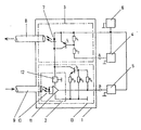
- the figure shows the basic circuit structure of an exemplary embodiment of a connection point of the optical transmission system according to the invention for control purposes which is constructed as a battery-powered digital terminal.
- connection point 1 consists of an optical receiver 2, an optical transmitter 3, a keyboard 4, a display device 5 (7-segment display) and a battery 6 for the operating power supply of the devices 2 to 5.
- the transmitter 3 controlled by the keyboard 4 is constructed from an LED 7, from which the optical signals are coupled directly into an outgoing optical fiber 8, a switching transistor T 1 and a base voltage divider R i , R 2 for level adjustment.
- optical signals arriving via an optical waveguide 9 are coupled directly into a photodiode 10, the electrical output signal of which is amplified by means of an amplifier 11 and fed to the display device 5.
- connection point 1 is also suitable for small supply currents or outputs, so that on the one hand the use of inexpensive, long-life and small batteries and on the other hand special applications such as data transmission in explosion-proof rooms are possible.
- a constant voltage regulator 12 is connected upstream of the amplifier 11.
- connection point 1 can be converted into a regeneration stage in a simple manner by a conductive connection of the circuit points A and B and can advantageously be used in continuous optical connections.
Landscapes
- Physics & Mathematics (AREA)
- Electromagnetism (AREA)
- Engineering & Computer Science (AREA)
- Computer Networks & Wireless Communication (AREA)
- Signal Processing (AREA)
- Optical Communication System (AREA)
Description
- Die Erfindung betrifft ein optisches Übertragungssystem für Duplex-Betrieb, bei dem der optische Sender und der optische Empfänger jeder Anschlußstelle der Übertragungsstrecke von der selben Spannungsquelle versorgt werden.
- Bei derartigen, zum Beispiel aus dem Buch "Optoelektronik Kurz und bündig" von Schmidt/ Feustel, Vogel-Verlag 1975, Seiten 65, 69, 137, 160, 172 und 220, bekannten Sender- und Empfängerschaltungen für optische Übertragungssysteme, wie sie etwa bei Bus-Systemen von Rechnern verwendet werden, erfolgt die Betriebsstromversorgung von Sender und Empfänger im Parallelbetrieb. Diese Art der Speisung ist wegen ihrer Einfachheit in allen Fällen sinnvoll, in denen keine Begrenzung der Leistung oder des Stromes gefordert ist. Wenn jedoch ein minimaler Stromverbrauch angestrebt wird - beispielsweise zur Erzielung einer hohen Lebensdauer und/oder kleiner Abmessung batteriegespeister Geräte - oder nur eine geringe Leistungsaufnahme der Anschlußstelle zulässig ist - etwa bei optischer Informationsübertragung in explosionsgeschützten Räumen - ist die Parallelspeisung häufig nicht mehr möglich. Zum Beispiel steht bei einer Spannung von 12 Volt und einer höchstzulässigen Leistung von 0,12 Watt nur ein Strom von 10 Milliampere zur Verfügung; dieser reicht jedoch nur knapp zur Versorgung des optischen Senders aber nicht zugleich auch des Empfängers aus. In solchen Fällen wurden bisher getrennte Spannungsquellen für die Betriebsstromversorgung des optischen Senders und Empfängers verwendet und das Übertragungssystem damit wesentlich verteuert.
- Der Erfindung liegt die Aufgabe zugrunde, ein Übertragungssystem der eingangsgenannten Art zu schaffen, das auf möglichst einfache und kostengünstige Weise auch für kleine Speiseströme beziehungsweise Speiseleistung en geeignet ist.
- Diese Aufgabe ist dadurch gelöst, daß der optische Sender und der optische Empfänger wenigstens einer Anschlußstelle bezüglich der Stromversorgung in Serie geschaltet sind und der optische Empfänger mit einer Zusatzschaltung eine Empfangseinheit bildet, die eine von der Ausgangsspannung des optischen Empfängers unabhängige Stromaufnahme aufweist. Die in bekannten praktischen Anwendungsfällen zur Verfung stehend Speisespannung reicht für den Betrieb der Sender- und Empfängerelektronik in aller Regel aus. Durch die erfindungsgemäße Serienschaltung ist nunmehr der Speisestrom so weit reduziert, daß eine hohe Batterielebensdauer gewährleistet ist und die in der Praxis relevanten Anforderungen an die Höchstwerte von Strom - beziehungsweise Leistungsaufnahme - stets erfüllbar sind.
- Zugleich ist durch die Zusatzschaltung eine hinsichtlicht der Stromaufnahme konstante Last (Empfangseinheit) gebildet und somit wirksam vermieden, daß sich durch Schankungen des Empfänger-Ausgangssignals (zum Beispiel Änderungen des logischen Zustandes bei einem digitalen Ausgangssignal) über entsprechende Schwankungen der Stromafnahme des Empfängers und damit des Stromes durch die Sender-LED unzulässige Änderungen des optischen Sender-Ausgangssignals ergeben können.
- Zur einfachen Realisierung dieser konstanten Last ist eine Ausbildung der Empfangseinheit gemäß Anspruch 2 besonders geeignet, wobei für die gesteuerte Stromquelle eine Reihe an sich bekannter, nach den Bedürfnissen des Einzelfalls auszuwählender Schaltungen zur Verfügung steht.
- In den Ansprüchen 3 und 4 sind zwei zweckmäßige Möglichkeiten zur Erzeugung des Steuersignals für die gesteuerte Stromquelle angegeben.
- Das erfindungsgemäße Übertragungssystem eignet sich im Gegensatz zum Stand der Technik auch zum Aufbau ganzer Übertragungslinien gemäß Anspruch 5, wobei die an beliebigen Stellen (auch nachträglich) in die Betriebsstromleitung einschaltbaren Anschlußstellen entweder als Endgeräte oder als Regeneratoren in einer durchgehenden optischen Verbindung verwendbar sind.
- Die Figur zeigt den prinzipiellen Shaltungsaufbau eines als batteriegespeistes digitales Endgerät aufgebauten Ausführungsbespieles einer Anschlüßstelle des erfindungsgemäßen optischen Übertragungssystem für Steuerzwecke.
- Die Anschlußstelle 1 besteht aus einem optischen Empfänger 2, einem optischen Sender 3, einer Tastatur 4, einer Anzeigeeinrichtung 5 (7-Segment-Display), sowie einer Batterie 6 zur Betriebsstromversorgung der angeführten Geräte 2 bis 5.
- Der von der Tastatur 4 angesteuerte Sender 3 ist aus einer LED 7, aus der die optischen Signale direkt in einen abgehenden Lichtwellenleiter 8 ausgekoppelt werden, einem Schalttransistor T1 sowie einem Basisspannungsteiler Ri, R2 zur Pegelanpassung aufgebaut.
- Die über einen Lichtwellenleiter 9 ankommenden optischen Signale werden direkt in eine Fotodiode 10 eingekoppelt, deren mittels eines Verstärkers 11 verstärktes elektrisches Ausgangssignal der Anzeigeeinrichtung 5 zugeführt wird.
- Bezüglich der Versorgungsspannung aus der Batterie 6 sind Empfänger 2 und Sender 3 in Serie geschaltet. Auf diese Weise ist die Anschlußstelle 1 auch für kleine Versorgungsströme beziehungsweise - Leistungen geeignet, sodaß einerseits der Einsatz kostengünstiger, langlebiger und kleiner Batterien und andererseits spezielle Anwendungen wie zum Beispiel Datenübertragung in explosionsgeschützten Räumen ermöglicht sind.
- Zur empfängerseitigen Stabilisierung der Versorgungsspannung unabhängig von der Batteriespannung und vom Schaltzustand des Transistors T1 des optischen Senders 3 ist dem Verstärker 11 ein Konstantspannungsregler 12 vorgeschaltet.
- Ohne zusätzliche Maßnahmen hätte nun jede Änderung des logischen Zustandes des Ausgangssignals des optischen Empfängers 2 eine entsprechende Schwankung von dessen Stromaufnahme und damit eine unzulässige Änderung der vom optischen Sender 3 in den Lichtwellenleiter 8 ausgekoppelten Lichtleistung zur Folge. Diese unerwünschte Rückwirkung ist auf einfache und wirkungsvolle Weise dadurch unterbunden, daß der optische Empfänger 2 mit einer dazu parallelen veränderbaren Stromquelle T2, R3 zu einer Empfangseinheit 13 zusammengeschaltet ist, bei der die Basis des in Emitterschaltung betriebenen Transistors T2 von der Ausgansspannung des Verstärkers 11 über einen ohmschen Widerstand R4 angesteuert wird und der Eingangsstrom durch entsprechende Bemessung dieses Widerstandes R4 sowie eines weiteren zwischen Basis und Masse eingeschalteten ohmschen Widerstandes R5 konstant gehalten ist.
- Die beschriebene Anschlußstelle 1 kann durch leitende Verbindung der Schaltungspunkte A und B auf einfache Weise in eine Regenerationsstufe umgewandelt und vorteilhaft in durchgehenden optischen Verbindungen eingesetzt werden.
Claims (5)
Priority Applications (1)
| Application Number | Priority Date | Filing Date | Title |
|---|---|---|---|
| AT84109752T ATE59748T1 (de) | 1983-09-27 | 1984-08-16 | Optisches uebertragungssystem fuer duplex-betrieb. |
Applications Claiming Priority (2)
| Application Number | Priority Date | Filing Date | Title |
|---|---|---|---|
| DE3334839 | 1983-09-27 | ||
| DE19833334839 DE3334839A1 (de) | 1983-09-27 | 1983-09-27 | Optisches uebertragungssystem fuer duplex-betrieb |
Publications (3)
| Publication Number | Publication Date |
|---|---|
| EP0141095A2 EP0141095A2 (de) | 1985-05-15 |
| EP0141095A3 EP0141095A3 (en) | 1988-03-16 |
| EP0141095B1 true EP0141095B1 (de) | 1991-01-02 |
Family
ID=6210129
Family Applications (1)
| Application Number | Title | Priority Date | Filing Date |
|---|---|---|---|
| EP84109752A Expired - Lifetime EP0141095B1 (de) | 1983-09-27 | 1984-08-16 | Optisches Übertragungssystem für Duplex-Betrieb |
Country Status (3)
| Country | Link |
|---|---|
| EP (1) | EP0141095B1 (de) |
| AT (1) | ATE59748T1 (de) |
| DE (2) | DE3334839A1 (de) |
Families Citing this family (1)
| Publication number | Priority date | Publication date | Assignee | Title |
|---|---|---|---|---|
| DE4228733A1 (de) * | 1992-08-28 | 1994-03-03 | Becker Autoradio | Teilnehmersystem mit mehreren durch elektrische Geräte gebildeten Teilnehmern |
Family Cites Families (4)
| Publication number | Priority date | Publication date | Assignee | Title |
|---|---|---|---|---|
| NL7306137A (de) * | 1973-05-03 | 1974-11-05 | ||
| DE2728880A1 (de) * | 1977-06-27 | 1979-01-18 | Paul Pernik | Lichtabtaster mit phototransistor |
| US4161650A (en) * | 1978-04-06 | 1979-07-17 | Lockheed Aircraft Corporation | Self-powered fiber optic interconnect system |
| FR2462067A1 (fr) * | 1979-07-18 | 1981-02-06 | Owens Corning Fiberglass Corp | Dispositif de transmission de donnees numeriques en serie |
-
1983
- 1983-09-27 DE DE19833334839 patent/DE3334839A1/de active Granted
-
1984
- 1984-08-16 DE DE8484109752T patent/DE3483814D1/de not_active Expired - Fee Related
- 1984-08-16 AT AT84109752T patent/ATE59748T1/de not_active IP Right Cessation
- 1984-08-16 EP EP84109752A patent/EP0141095B1/de not_active Expired - Lifetime
Also Published As
| Publication number | Publication date |
|---|---|
| DE3334839C2 (de) | 1987-07-30 |
| DE3483814D1 (de) | 1991-02-07 |
| EP0141095A2 (de) | 1985-05-15 |
| EP0141095A3 (en) | 1988-03-16 |
| DE3334839A1 (de) | 1985-04-11 |
| ATE59748T1 (de) | 1991-01-15 |
Similar Documents
| Publication | Publication Date | Title |
|---|---|---|
| DE2933029C2 (de) | ||
| DE3934007C2 (de) | Schaltungsanordnung zur Übertragung von Meßwertsignalen von einer Sendestation zu einer Empfangsstation | |
| US4315207A (en) | Current controlled battery feed circuit | |
| DE1591223A1 (de) | Automatisch arbeitendes Pruefgeraet fuer elektronische Schaltkreise | |
| ES8106387A1 (es) | Un aparato para regular la corriente suministrada a una li- nea telefonica | |
| DE2302798A1 (de) | Steuerschaltung fuer induktive verbraucher | |
| DE69205064T2 (de) | Quartz-Schaltung mit niedriger Leistung. | |
| US3970784A (en) | Transmission system | |
| US4658201A (en) | Output circuit for diode-or connected positive three terminal voltage regulators | |
| EP0124030B1 (de) | Stromversorgung für seriengespeiste elektronische Schaltungen | |
| US2594006A (en) | Voltage power supply | |
| DE3334839C2 (de) | ||
| EP0021410B1 (de) | Schaltungsanordnung für einen elektronischen Gleichstrom-Telegrafiesender | |
| EP1110329A1 (de) | Elektronische schaltungsanordnung | |
| DE102007030569B4 (de) | Schaltungsanordnung und Verfahren zum Auswerten eines Datensignals | |
| DE3365424D1 (en) | Active impedance line feed circuit | |
| US2483755A (en) | Voltage regulator | |
| US4757251A (en) | Circuit arrangement for high-voltage adjustment | |
| EP0292804A2 (de) | Schaltungsanordnung zur potentialfreien Erfassung von binären Signalen | |
| DE19517492B4 (de) | Analoge Stromschnittstelle | |
| DE2946306C2 (de) | Verstärkerschaltung mit vorgebbarem Wechselstrominnenwiderstand | |
| DE1248731B (de) | UEberwachungseinrichtung fuer Nachrichten-UEbertragungsanlagen zur Fernpruefung von Abschnitten der UEbertragungsstrecke | |
| DE3246144C2 (de) | Schaltungsanordnung zur Stromkonstanthaltung | |
| DE3743055A1 (de) | Schaltungsanordnung zur speisung von zusatzschaltungen eines fernsprechapparates | |
| EP0037940A1 (de) | Schaltungsanordnung zum zweidrähtigen Anschluss eines Fernsprechteilnehmers an je eine Leitung für abgehende und ankommende Signale |
Legal Events
| Date | Code | Title | Description |
|---|---|---|---|
| PUAI | Public reference made under article 153(3) epc to a published international application that has entered the european phase |
Free format text: ORIGINAL CODE: 0009012 |
|
| AK | Designated contracting states |
Designated state(s): AT CH DE FR GB IT LI NL SE |
|
| PUAL | Search report despatched |
Free format text: ORIGINAL CODE: 0009013 |
|
| AK | Designated contracting states |
Kind code of ref document: A3 Designated state(s): AT CH DE FR GB IT LI NL SE |
|
| 17P | Request for examination filed |
Effective date: 19880411 |
|
| RAP1 | Party data changed (applicant data changed or rights of an application transferred) |
Owner name: RICHARD HIRSCHMANN GMBH & CO. |
|
| 17Q | First examination report despatched |
Effective date: 19900330 |
|
| GRAA | (expected) grant |
Free format text: ORIGINAL CODE: 0009210 |
|
| AK | Designated contracting states |
Kind code of ref document: B1 Designated state(s): AT CH DE FR GB IT LI NL SE |
|
| REF | Corresponds to: |
Ref document number: 59748 Country of ref document: AT Date of ref document: 19910115 Kind code of ref document: T |
|
| ITF | It: translation for a ep patent filed | ||
| REF | Corresponds to: |
Ref document number: 3483814 Country of ref document: DE Date of ref document: 19910207 |
|
| GBT | Gb: translation of ep patent filed (gb section 77(6)(a)/1977) | ||
| ET | Fr: translation filed | ||
| PLBE | No opposition filed within time limit |
Free format text: ORIGINAL CODE: 0009261 |
|
| STAA | Information on the status of an ep patent application or granted ep patent |
Free format text: STATUS: NO OPPOSITION FILED WITHIN TIME LIMIT |
|
| 26N | No opposition filed | ||
| PGFP | Annual fee paid to national office [announced via postgrant information from national office to epo] |
Ref country code: SE Payment date: 19930506 Year of fee payment: 10 |
|
| PGFP | Annual fee paid to national office [announced via postgrant information from national office to epo] |
Ref country code: FR Payment date: 19930628 Year of fee payment: 10 |
|
| PGFP | Annual fee paid to national office [announced via postgrant information from national office to epo] |
Ref country code: CH Payment date: 19930715 Year of fee payment: 10 |
|
| PGFP | Annual fee paid to national office [announced via postgrant information from national office to epo] |
Ref country code: GB Payment date: 19930730 Year of fee payment: 10 |
|
| PGFP | Annual fee paid to national office [announced via postgrant information from national office to epo] |
Ref country code: DE Payment date: 19930810 Year of fee payment: 10 |
|
| PGFP | Annual fee paid to national office [announced via postgrant information from national office to epo] |
Ref country code: AT Payment date: 19930826 Year of fee payment: 10 |
|
| PGFP | Annual fee paid to national office [announced via postgrant information from national office to epo] |
Ref country code: NL Payment date: 19930831 Year of fee payment: 10 |
|
| PG25 | Lapsed in a contracting state [announced via postgrant information from national office to epo] |
Ref country code: GB Effective date: 19940816 Ref country code: AT Effective date: 19940816 |
|
| PG25 | Lapsed in a contracting state [announced via postgrant information from national office to epo] |
Ref country code: SE Effective date: 19940817 |
|
| PG25 | Lapsed in a contracting state [announced via postgrant information from national office to epo] |
Ref country code: LI Effective date: 19940831 Ref country code: CH Effective date: 19940831 |
|
| EAL | Se: european patent in force in sweden |
Ref document number: 84109752.0 |
|
| PG25 | Lapsed in a contracting state [announced via postgrant information from national office to epo] |
Ref country code: NL Effective date: 19950301 |
|
| GBPC | Gb: european patent ceased through non-payment of renewal fee |
Effective date: 19940816 |
|
| NLV4 | Nl: lapsed or anulled due to non-payment of the annual fee | ||
| PG25 | Lapsed in a contracting state [announced via postgrant information from national office to epo] |
Ref country code: FR Effective date: 19950428 |
|
| REG | Reference to a national code |
Ref country code: CH Ref legal event code: PL |
|
| PG25 | Lapsed in a contracting state [announced via postgrant information from national office to epo] |
Ref country code: DE Effective date: 19950503 |
|
| EUG | Se: european patent has lapsed |
Ref document number: 84109752.0 |
|
| REG | Reference to a national code |
Ref country code: FR Ref legal event code: ST |