EP0140722B1 - High volume dough piece production apparatus - Google Patents
High volume dough piece production apparatus Download PDFInfo
- Publication number
- EP0140722B1 EP0140722B1 EP84401650A EP84401650A EP0140722B1 EP 0140722 B1 EP0140722 B1 EP 0140722B1 EP 84401650 A EP84401650 A EP 84401650A EP 84401650 A EP84401650 A EP 84401650A EP 0140722 B1 EP0140722 B1 EP 0140722B1
- Authority
- EP
- European Patent Office
- Prior art keywords
- dough
- conveyor
- nozzles
- inlet
- rod
- Prior art date
- Legal status (The legal status is an assumption and is not a legal conclusion. Google has not performed a legal analysis and makes no representation as to the accuracy of the status listed.)
- Expired
Links
- 238000004519 manufacturing process Methods 0.000 title claims description 6
- 238000001125 extrusion Methods 0.000 claims abstract description 15
- 230000007246 mechanism Effects 0.000 claims abstract description 14
- 230000009977 dual effect Effects 0.000 claims abstract description 7
- 238000005520 cutting process Methods 0.000 claims description 4
- 230000015572 biosynthetic process Effects 0.000 claims description 3
- 238000004806 packaging method and process Methods 0.000 description 6
- 125000006850 spacer group Chemical group 0.000 description 6
- 230000000694 effects Effects 0.000 description 4
- 230000001788 irregular Effects 0.000 description 2
- 238000000034 method Methods 0.000 description 2
- 239000002245 particle Substances 0.000 description 2
- 235000021544 chips of chocolate Nutrition 0.000 description 1
- 238000000151 deposition Methods 0.000 description 1
- 238000006073 displacement reaction Methods 0.000 description 1
- 238000003754 machining Methods 0.000 description 1
- 230000001360 synchronised effect Effects 0.000 description 1
Images


Classifications
-
- A—HUMAN NECESSITIES
- A21—BAKING; EDIBLE DOUGHS
- A21C—MACHINES OR EQUIPMENT FOR MAKING OR PROCESSING DOUGHS; HANDLING BAKED ARTICLES MADE FROM DOUGH
- A21C5/00—Dough-dividing machines
-
- A—HUMAN NECESSITIES
- A21—BAKING; EDIBLE DOUGHS
- A21C—MACHINES OR EQUIPMENT FOR MAKING OR PROCESSING DOUGHS; HANDLING BAKED ARTICLES MADE FROM DOUGH
- A21C11/00—Other machines for forming the dough into its final shape before cooking or baking
- A21C11/10—Other machines for forming the dough into its final shape before cooking or baking combined with cutting apparatus
-
- A—HUMAN NECESSITIES
- A21—BAKING; EDIBLE DOUGHS
- A21C—MACHINES OR EQUIPMENT FOR MAKING OR PROCESSING DOUGHS; HANDLING BAKED ARTICLES MADE FROM DOUGH
- A21C3/00—Machines or apparatus for shaping batches of dough before subdivision
- A21C3/04—Dough-extruding machines ; Hoppers with moving elements, e.g. rollers or belts as wall elements for drawing the dough
-
- B—PERFORMING OPERATIONS; TRANSPORTING
- B29—WORKING OF PLASTICS; WORKING OF SUBSTANCES IN A PLASTIC STATE IN GENERAL
- B29C—SHAPING OR JOINING OF PLASTICS; SHAPING OF MATERIAL IN A PLASTIC STATE, NOT OTHERWISE PROVIDED FOR; AFTER-TREATMENT OF THE SHAPED PRODUCTS, e.g. REPAIRING
- B29C48/00—Extrusion moulding, i.e. expressing the moulding material through a die or nozzle which imparts the desired form; Apparatus therefor
- B29C48/25—Component parts, details or accessories; Auxiliary operations
- B29C48/36—Means for plasticising or homogenising the moulding material or forcing it through the nozzle or die
- B29C48/395—Means for plasticising or homogenising the moulding material or forcing it through the nozzle or die using screws surrounded by a cooperating barrel, e.g. single screw extruders
- B29C48/40—Means for plasticising or homogenising the moulding material or forcing it through the nozzle or die using screws surrounded by a cooperating barrel, e.g. single screw extruders using two or more parallel screws or at least two parallel non-intermeshing screws, e.g. twin screw extruders
-
- B—PERFORMING OPERATIONS; TRANSPORTING
- B29—WORKING OF PLASTICS; WORKING OF SUBSTANCES IN A PLASTIC STATE IN GENERAL
- B29C—SHAPING OR JOINING OF PLASTICS; SHAPING OF MATERIAL IN A PLASTIC STATE, NOT OTHERWISE PROVIDED FOR; AFTER-TREATMENT OF THE SHAPED PRODUCTS, e.g. REPAIRING
- B29C48/00—Extrusion moulding, i.e. expressing the moulding material through a die or nozzle which imparts the desired form; Apparatus therefor
- B29C48/25—Component parts, details or accessories; Auxiliary operations
- B29C48/36—Means for plasticising or homogenising the moulding material or forcing it through the nozzle or die
- B29C48/395—Means for plasticising or homogenising the moulding material or forcing it through the nozzle or die using screws surrounded by a cooperating barrel, e.g. single screw extruders
- B29C48/455—Screws arranged to convey material towards each other, e.g. separate screws arranged after each other and feeding in opposite directions
-
- Y—GENERAL TAGGING OF NEW TECHNOLOGICAL DEVELOPMENTS; GENERAL TAGGING OF CROSS-SECTIONAL TECHNOLOGIES SPANNING OVER SEVERAL SECTIONS OF THE IPC; TECHNICAL SUBJECTS COVERED BY FORMER USPC CROSS-REFERENCE ART COLLECTIONS [XRACs] AND DIGESTS
- Y10—TECHNICAL SUBJECTS COVERED BY FORMER USPC
- Y10T—TECHNICAL SUBJECTS COVERED BY FORMER US CLASSIFICATION
- Y10T83/00—Cutting
- Y10T83/202—With product handling means
- Y10T83/2092—Means to move, guide, or permit free fall or flight of product
- Y10T83/2094—Means to move product at speed different from work speed
Definitions
- the present invention relates to apparatus for producing dough pieces, and more particularly, high volume apparatus for producing dough pieces cut from extruded dough according to the preamble of claim 1.
- US-A-4 332 538 describes a dough piece production apparatus in which a single stream of dough is fed from a hopper by means of a pair of intermeshing screws through metering device and then through a dispensing nozzle, the stream of dough being cut into a series of dough pieces at the nozzle by a reciprocating paddle.
- US ⁇ A ⁇ 2 838 013 describes a dough piece production apparatus in which a dough feeding assembly feeds dough from a hopper through a nozzle, and the resulting extruded rope of dough is cut into sections (dough pieces) by an oscillating cutter.
- This cutter undergoes a complex reciprocating motion involving movements parallel to the direction of extrusion of the dough, as well as cutting movements perpendicular to the direction of extrusion of the dough.
- the cut dough pieces fall onto a conveyor disposed below the nozzle.
- the apparatus may include a plurality of nozzles spaced from one another across the width of the conveyor, each nozzle depositing a separate stream of dough pieces onto the conveyor.
- a wire cut machine such as those described in the two aforementioned patents, deposits dough pieces on to a conveyor belt in parallel rows or columns.
- the normal speed of operation of these machines is between 150 and 180 pieces per minute for each line deposited on the conveyor At these speeds, the wire cuts cleanly through the extruding dough without transferring a significant amount of energy to the piece cut off.
- the pieces fall vertically onto the conveyor in a consistent uniform pattern.
- these machines run at speeds greater than 180 pieces per minute, the pattern is disrupted in two ways. At these high speeds the machine begins to vibrate and this effects the placement of the dough pieces.
- the wire because of its speed, transfers sufficient energy into the pieces to throw the pieces horizontally in an unpredictable manner.
- the dough contains particles such as chocolate chips, the energy transferred to the pieces varies according to the number and location of the particles which are struck by the wire as it passes through the extrusion.
- the dough pieces are deposited on the conveyor in an irregular pattern which effects the baking and packaging operations.
- Modern efficient automated packaging machinery requires that the baked articles be arranged in well defined rows. Also, wire cut dough pieces generally spread during baking. Therefore, dough pieces which are too close together fuse into one large irregular baked piece and must be discarded. Modern packaging methods also require that the dough pieces be uniform in size so as to produce baked products of uniform size and weight which can be processed by automatic machinery.
- Another object is to provide such apparatus for producing wire cut dough pieces arranged in well defined rows.
- Another object is to provide extrusion apparatus containing simple and effective means for balancing the flow of dough from a plurality of nozzles fed by a common source.
- the foregoing objects are accomplished by providing a conveyor and a dough piece former having plural outlets spaced along the direction of travel of the conveyor, the speed of the conveyor being related to the operating speed of the dough piece former so as to form a line of evenly spaced dough pieces: and by providing throttling apparatus for balancing the flow of dough from a common source to individual nozzles according to the characterising part of claim 1.
- apparatus which includes a conveyor 10 having a belt 11, and a wire cut dough machine 12 positioned over the conveyor.
- the machine 12 incorporates a series of dual extruders 14 spaced across the conveyor 10, each having two extrusion nozzles 15, 16.
- the extruders 14 are fed from a common hopper 17 by two feed rolls 18, 19.
- the hopper 17 and the rolls 18, 19 extend transversely of the conveyor across the extruders.
- a wire cut mechanism 20 simultaneously slices through the dough extruding from the nozzles 15, 16 to form dough pieces which fall upon the conveyor belt.
- each of the extruders 14 comprises a dual auger 24 fitted into a bore 25 in an auger housing 26.
- the nozzles 15, 16 are fastened to the bottom of the housing 26 in line with discharge openings 27, 28 at opposite ends of the dual auger.
- the dual auger 24 comprises a right hand thread section 29 and a left hand thread section 30 which meet at the center beneath the inlet opening 22.
- the minor diameter (the diameter of the central body) is increased to develop a greater dough pressure at the nozzles.
- the shafts 32 on which the augers are formed are journalled at one end in a bearing block 34 and extend in the opposite direction through a block 35 which supports the drive motor 36 and gear train 37 which power the augers.
- the gear train includes a drive gear 39 mounted on the end of each shaft 32 and intermeshed with the adjacent gears 39. Since the gear train drives adjacent shafts in opposite directions, the augers formed on adjacent shafts are pitched oppositely.
- the shafts 32 are locked against axial movement with respect to the block 35 by suitable thrust bearings.
- the support block 35 is mounted on a pair of shafts 40 which extend through the block 35 and into a bore 41 in the auger housing 26, as shown in Fig. 2.
- a rod 42 threaded at both ends, extends through the auger housing and is screwed into the end of the shaft 40 in the bore 41.
- a nut 44 is provided on the free end of the rod 42 to position the support block 35, and thereby the augers 24, relative to the auger housing 26.
- the position of the augers 24 with respect to the inlets 22 effects the relative rate of dough flow to the left hand and right hand portions of the auger.
- each shaft 40 rests, for support, on the edge of a vertical plate 45, as shown in Fig. 1.
- a tube 46 provided with a slot in the bottom to admit the plate 45, surrounds the free end of each shaft 40.
- Each tube 46 is provided with a cap 47 on its free end and a flange 49 on the end adjacent the block 35.
- a bolt 50 extending through the cap 47 is threaded into the end of the shaft 40 to urge the sleeve to the right (as seen in Fig. 1) and position the flange 49 against the block 35.
- a spacer 51 is positioned between the block 35 and the auger housing 26.
- the spacers shown in plan view in Fig. 7, are provided with counter-sunk bolt holes 52 and are bolted to the housing 26.
- the thickness of the spacer needed is determined by trial and error using thin shims where the spacer is.
- the machine 12 is placed in operation and the spacing between the block 35 and the housing 26 is adjusted by the adding and removing of shims until the flow rate from the nozzles 15 and the nozzles 16 are equal. Spacers of the required thickness are then substituted for the shims.
- the wire cut dough machine could contain 18 or more augers spaced across the conveyor belt.
- the augers and bores are formed by machining, and, even with strict tolerances, some variations from part to part are unavoidable.
- the flow rate from hopper to the inlet openings tend to decrease at the ends of the hopper where friction with the end walls of the hopper produces a degree of laminar flow. The effects of these factors would result in variations in the size of the dough pieces in some rows with respect to that in others. Therefore, individually adjustable throttling mechanisms are provided at each inlet 22 to balance the output of the extruders 14.
- a choke rod 54 extends through the auger housing 26 to intersect the edge of each opening 22.
- the rods 54 are cut out to provide a curved surface 55 which matches the contour of the edge of the inlet 22.
- the inlet is unrestricted allowing full flow into the dual extruder.
- Each rod 54 is rotationally positioned by means of an adjustment plate 56.
- a square formation 57 is provided on the free end of the rod.
- the plate 56 has a matching square hole (not shown). The plate is mounted on the formation 57 and held by a bolt 58.
- the shape of the adjustment plate 56 approximates a circular quadrant.
- a curved slot 59 is formed in the plate along a 90 degree circular arc having its center at the axis of the rod 54.
- Each adjustment plate 56 is locked in position by a bolt 60 which extends through the curved slot, into the edge of a block 61 mounted on the auger housing 26.
- the wire cut mechanism 20 includes a guide rod 62 mounted on each end of the machine 12 by a bracket 64. Sliding blocks 65 and 66 are mounted on each of the rods 62 on either side of the support bracket 64. Wire holding fingers 67, 68 are mounted on pivoted rods (not shown) which extend between the blocks 65, 66. Wires are stretched across the conveyor belt 11 between the free ends of the fingers 67 and between the free ends of the fingers 68.
- the sliding blocks 65 and 66 on each side of the machine are interconnected by bars 69 for synchronous motion. The sliding blocks are reciprocated upon the guide rods by a crank mechanism 70 driven by a motor 71. The reciprocating motion of the blocks 65, 66 move the cutting wires past the nozzles.
- Another crank mechanism (not shown) also driven by the motor 71 pivots the wire holding fingers 67, 68 upwardly toward the nozzles at the beginning of the cut stroke so that the wires move across the faces of the nozzles as the extrusion is sliced.
- the wire holding fingers are pivoted downwardly so that the wires pass below the end of the extruding dough streams.
- the conveyor 10 is driven by a motor 72 provided with a speed control unit 74.
- the speed of the conveyor is adjusted with relation to the speed of operation of the cut-off mechanism 20, so that, between dough piece drops, the conveyor belt 11 moves a distance equal to two thirds of the spacing of the nozzles 15 and 16.
- Fig 8 there is shown the drop pattern for one set of nozzles 15, 16.
- the nozzles are positioned above the circles marked "Drop Point" and are separated by a distance X as indicated.
- the circles on the conveyor belt 11 represent the dough pieces formed on four consecutive drops. The position of these dough pieces is that which they occupy at the time the fourth drop is made.
- the dough pieces marked "1" were dropped on the first drop and have moved through a distance of three times 2/3X.
- the dough pieces marked "2" were dropped on the second drop and have moved through a distance of two times 2/3X.
- the dough pieces marked "3" were dropped on third drop and have moved the distance 2/3X.
- the "A” pieces were dropped from a nozzle 15 and the “B” pieces were dropped from a nozzle 16.
- the “A” pieces are separated from each other by a distance of 2/3X.
- the “B” pieces are likewise separated from each other by a distance of 2/3X, and each "B” piece falls halfway between two consecutive "A” pieces.
- a line of dough pieces are formed in which the consecutive pieces are separated by one third the distance between the nozzles.
- the present invention provides apparatus for producing dough pieces in high volume which are arranged in well defined rows and are of uniform size and weight.
Landscapes
- Engineering & Computer Science (AREA)
- Life Sciences & Earth Sciences (AREA)
- Food Science & Technology (AREA)
- Mechanical Engineering (AREA)
- Manufacturing And Processing Devices For Dough (AREA)
- Bakery Products And Manufacturing Methods Therefor (AREA)
- Preparation Of Fruits And Vegetables (AREA)
- Debarking, Splitting, And Disintegration Of Timber (AREA)
Abstract
Description
- The present invention relates to apparatus for producing dough pieces, and more particularly, high volume apparatus for producing dough pieces cut from extruded dough according to the preamble of claim 1.
- US-A-4 332 538 describes a dough piece production apparatus in which a single stream of dough is fed from a hopper by means of a pair of intermeshing screws through metering device and then through a dispensing nozzle, the stream of dough being cut into a series of dough pieces at the nozzle by a reciprocating paddle.
- US―A―2 838 013 describes a dough piece production apparatus in which a dough feeding assembly feeds dough from a hopper through a nozzle, and the resulting extruded rope of dough is cut into sections (dough pieces) by an oscillating cutter. This cutter undergoes a complex reciprocating motion involving movements parallel to the direction of extrusion of the dough, as well as cutting movements perpendicular to the direction of extrusion of the dough.
- In the types of apparatus described in the two aforementioned patents, the cut dough pieces fall onto a conveyor disposed below the nozzle. To secure increased production rates, the apparatus may include a plurality of nozzles spaced from one another across the width of the conveyor, each nozzle depositing a separate stream of dough pieces onto the conveyor.
- In the baking industry, there are continuous technological efforts to increase the rate of product flow through the dough forming, baking and packaging operations of the manufacturing process.
- When dough pieces for certain baked products are formed by the wire cut method, in which dough is extruded from a horizontally oriented die and sections of the dough are sliced off by a thin moving wire (as in the two aforementioned patents), it has been found that the speed of the baking and packaging operations have advanced to the point where the commercially available wire cut machines cannot supply dough pieces at a rate sufficient to match that of the baking and packaging operations. While the extrusion rate can be increased considerably without difficulty, there is a practical limit to the speed at which the cutting wire will efficiently form dough pieces.
- A wire cut machine, such as those described in the two aforementioned patents, deposits dough pieces on to a conveyor belt in parallel rows or columns. The normal speed of operation of these machines is between 150 and 180 pieces per minute for each line deposited on the conveyor At these speeds, the wire cuts cleanly through the extruding dough without transferring a significant amount of energy to the piece cut off. The pieces fall vertically onto the conveyor in a consistent uniform pattern. When these machines run at speeds greater than 180 pieces per minute, the pattern is disrupted in two ways. At these high speeds the machine begins to vibrate and this effects the placement of the dough pieces. Also, the wire, because of its speed, transfers sufficient energy into the pieces to throw the pieces horizontally in an unpredictable manner. In addition, when the dough contains particles such as chocolate chips, the energy transferred to the pieces varies according to the number and location of the particles which are struck by the wire as it passes through the extrusion.
- As a result of this unpredicatable horizontal displacement of the dough pieces, the dough pieces are deposited on the conveyor in an irregular pattern which effects the baking and packaging operations. Modern efficient automated packaging machinery requires that the baked articles be arranged in well defined rows. Also, wire cut dough pieces generally spread during baking. Therefore, dough pieces which are too close together fuse into one large irregular baked piece and must be discarded. Modern packaging methods also require that the dough pieces be uniform in size so as to produce baked products of uniform size and weight which can be processed by automatic machinery.
- It is therefore an object of the present invention to provide apparatus for producing dough pieces in high volume.
- Another object is to provide such apparatus for producing wire cut dough pieces arranged in well defined rows.
- Another object is to provide extrusion apparatus containing simple and effective means for balancing the flow of dough from a plurality of nozzles fed by a common source.
- The foregoing objects are accomplished by providing a conveyor and a dough piece former having plural outlets spaced along the direction of travel of the conveyor, the speed of the conveyor being related to the operating speed of the dough piece former so as to form a line of evenly spaced dough pieces: and by providing throttling apparatus for balancing the flow of dough from a common source to individual nozzles according to the characterising part of claim 1.
- A preferred embodiment of the invention have been chosen for purpose of illustration and description and is shown in the accompanying drawings, forming a part of the specification, wherein:
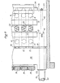
- Fig. 1 is a side elevational view of a wire cut, dough piece forming apparatus according to the present invention,
- Fig. 2 is a plan view taken generally along line 2-2 on Fig. 1,
- Fig. 3 is an enlarged view of a portion of Fig, 2 showing flow adjusting mechanisms,
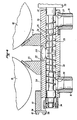
- Fig. 4 is a sectional view taken along line 4-4 on Fig. 3,
- Fig. 5 is an end view of the arrangement shown on Fig. 3,
- Fig. 6 is a side view of a flow adjusting rod,
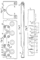
- Fig. 7 is a front view of an auger positioning spacer, and
- Fig. 8 is a plan view of a portion of the conveyor illustrating the drop sequence of dough pieces in forming a row of dough pieces.
- Referring to the drawings in detail, there is shown apparatus according to the present invention which includes a
conveyor 10 having abelt 11, and a wirecut dough machine 12 positioned over the conveyor. Themachine 12 incorporates a series ofdual extruders 14 spaced across theconveyor 10, each having twoextrusion nozzles extruders 14 are fed from acommon hopper 17 by twofeed rolls hopper 17 and therolls wire cut mechanism 20 simultaneously slices through the dough extruding from thenozzles - Referring now to Fig. 4, dough is forced by the
rolls scrapers 21 into theinlets 22 of the extruders. Each of theextruders 14 comprises adual auger 24 fitted into abore 25 in anauger housing 26. Thenozzles housing 26 in line withdischarge openings - The
dual auger 24 comprises a righthand thread section 29 and a lefthand thread section 30 which meet at the center beneath the inlet opening 22. - At the discharge ends of the augers, the minor diameter (the diameter of the central body) is increased to develop a greater dough pressure at the nozzles.
- The
shafts 32 on which the augers are formed are journalled at one end in abearing block 34 and extend in the opposite direction through ablock 35 which supports thedrive motor 36 andgear train 37 which power the augers. The gear train includes adrive gear 39 mounted on the end of eachshaft 32 and intermeshed with theadjacent gears 39. Since the gear train drives adjacent shafts in opposite directions, the augers formed on adjacent shafts are pitched oppositely. Theshafts 32 are locked against axial movement with respect to theblock 35 by suitable thrust bearings. - The
support block 35 is mounted on a pair ofshafts 40 which extend through theblock 35 and into abore 41 in theauger housing 26, as shown in Fig. 2. Arod 42, threaded at both ends, extends through the auger housing and is screwed into the end of theshaft 40 in thebore 41. Anut 44 is provided on the free end of therod 42 to position thesupport block 35, and thereby theaugers 24, relative to theauger housing 26. The position of theaugers 24 with respect to theinlets 22 effects the relative rate of dough flow to the left hand and right hand portions of the auger. - The free end of each
shaft 40 rests, for support, on the edge of avertical plate 45, as shown in Fig. 1. Atube 46, provided with a slot in the bottom to admit theplate 45, surrounds the free end of eachshaft 40. - Each
tube 46 is provided with acap 47 on its free end and aflange 49 on the end adjacent theblock 35. Abolt 50 extending through thecap 47 is threaded into the end of theshaft 40 to urge the sleeve to the right (as seen in Fig. 1) and position theflange 49 against theblock 35. - Referring to Fig. 2, a
spacer 51 is positioned between theblock 35 and theauger housing 26. The spacers, shown in plan view in Fig. 7, are provided withcounter-sunk bolt holes 52 and are bolted to thehousing 26. The thickness of the spacer needed is determined by trial and error using thin shims where the spacer is. Themachine 12 is placed in operation and the spacing between theblock 35 and thehousing 26 is adjusted by the adding and removing of shims until the flow rate from thenozzles 15 and thenozzles 16 are equal. Spacers of the required thickness are then substituted for the shims. - In a conventional bakery setup, the wire cut dough machine could contain 18 or more augers spaced across the conveyor belt. The augers and bores are formed by machining, and, even with strict tolerances, some variations from part to part are unavoidable. Also, the flow rate from hopper to the inlet openings tend to decrease at the ends of the hopper where friction with the end walls of the hopper produces a degree of laminar flow. The effects of these factors would result in variations in the size of the dough pieces in some rows with respect to that in others. Therefore, individually adjustable throttling mechanisms are provided at each
inlet 22 to balance the output of theextruders 14. - As shown in Figs. 3 and 4, a
choke rod 54 extends through theauger housing 26 to intersect the edge of eachopening 22. Therods 54 are cut out to provide acurved surface 55 which matches the contour of the edge of theinlet 22. When thesurface 55 is vertically oriented, the inlet is unrestricted allowing full flow into the dual extruder. As therod 54 is rotated through 90 degrees, the restriction provided by the rod increases to a maximum. Eachrod 54 is rotationally positioned by means of anadjustment plate 56. Asquare formation 57 is provided on the free end of the rod. Theplate 56 has a matching square hole (not shown). The plate is mounted on theformation 57 and held by abolt 58. - Referring also to Fig. 5, the shape of the
adjustment plate 56 approximates a circular quadrant. Acurved slot 59 is formed in the plate along a 90 degree circular arc having its center at the axis of therod 54. Eachadjustment plate 56 is locked in position by abolt 60 which extends through the curved slot, into the edge of ablock 61 mounted on theauger housing 26. - The wire cut
mechanism 20 includes aguide rod 62 mounted on each end of themachine 12 by abracket 64. Slidingblocks 65 and 66 are mounted on each of therods 62 on either side of thesupport bracket 64.Wire holding fingers blocks 65, 66. Wires are stretched across theconveyor belt 11 between the free ends of thefingers 67 and between the free ends of thefingers 68. The sliding blocks 65 and 66 on each side of the machine are interconnected bybars 69 for synchronous motion. The sliding blocks are reciprocated upon the guide rods by acrank mechanism 70 driven by amotor 71. The reciprocating motion of theblocks 65, 66 move the cutting wires past the nozzles. Another crank mechanism (not shown) also driven by themotor 71 pivots thewire holding fingers - The
conveyor 10 is driven by amotor 72 provided with aspeed control unit 74. The speed of the conveyor is adjusted with relation to the speed of operation of the cut-off mechanism 20, so that, between dough piece drops, theconveyor belt 11 moves a distance equal to two thirds of the spacing of thenozzles nozzles conveyor belt 11 represent the dough pieces formed on four consecutive drops. The position of these dough pieces is that which they occupy at the time the fourth drop is made. The dough pieces marked "1" were dropped on the first drop and have moved through a distance of threetimes 2/3X. The dough pieces marked "2" were dropped on the second drop and have moved through a distance of twotimes 2/3X. The dough pieces marked "3" were dropped on third drop and have moved thedistance 2/3X. - Of these pieces, the "A" pieces were dropped from a
nozzle 15 and the "B" pieces were dropped from anozzle 16. The "A" pieces are separated from each other by a distance of 2/3X. The "B" pieces are likewise separated from each other by a distance of 2/3X, and each "B" piece falls halfway between two consecutive "A" pieces. Thus a line of dough pieces are formed in which the consecutive pieces are separated by one third the distance between the nozzles. - It will be seen from the foregoing that the present invention provides apparatus for producing dough pieces in high volume which are arranged in well defined rows and are of uniform size and weight.
Claims (11)
Priority Applications (1)
| Application Number | Priority Date | Filing Date | Title |
|---|---|---|---|
| AT84401650T ATE38312T1 (en) | 1983-08-11 | 1984-08-08 | MACHINE FOR PRODUCTION OF DOUGH IN LARGER QUANTITIES. |
Applications Claiming Priority (2)
| Application Number | Priority Date | Filing Date | Title |
|---|---|---|---|
| US06/522,293 US4685878A (en) | 1983-08-11 | 1983-08-11 | High volume dough piece production apparatus |
| US522293 | 1983-08-11 |
Related Child Applications (1)
| Application Number | Title | Priority Date | Filing Date |
|---|---|---|---|
| EP87100874.4 Division-Into | 1987-01-22 |
Publications (3)
| Publication Number | Publication Date |
|---|---|
| EP0140722A2 EP0140722A2 (en) | 1985-05-08 |
| EP0140722A3 EP0140722A3 (en) | 1985-06-05 |
| EP0140722B1 true EP0140722B1 (en) | 1988-11-02 |
Family
ID=24080296
Family Applications (2)
| Application Number | Title | Priority Date | Filing Date |
|---|---|---|---|
| EP84401650A Expired EP0140722B1 (en) | 1983-08-11 | 1984-08-08 | High volume dough piece production apparatus |
| EP87100874A Expired - Lifetime EP0238798B1 (en) | 1983-08-11 | 1984-08-08 | High volume dough piece production apparatus |
Family Applications After (1)
| Application Number | Title | Priority Date | Filing Date |
|---|---|---|---|
| EP87100874A Expired - Lifetime EP0238798B1 (en) | 1983-08-11 | 1984-08-08 | High volume dough piece production apparatus |
Country Status (7)
| Country | Link |
|---|---|
| US (1) | US4685878A (en) |
| EP (2) | EP0140722B1 (en) |
| JP (1) | JPS6043329A (en) |
| AT (2) | ATE82670T1 (en) |
| AU (1) | AU570985B2 (en) |
| CA (1) | CA1238526A (en) |
| DE (2) | DE3474898D1 (en) |
Families Citing this family (23)
| Publication number | Priority date | Publication date | Assignee | Title |
|---|---|---|---|---|
| US5015490A (en) * | 1989-06-07 | 1991-05-14 | Nabisco Brands, Inc. | Production of extruded baked products without oil separation |
| US5124161A (en) * | 1989-06-07 | 1992-06-23 | Nabisco Brands, Inc. | Filled, microwave expandable snack food product and method and apparatus for its production |
| US4938127A (en) * | 1989-06-07 | 1990-07-03 | Nabisco Brands, Inc. | Extruder and continuous mixer arrangement for producing an at least partially baked product having a cookie-like crumb structure including a post-extrusion radio frequency device |
| US5071668A (en) * | 1989-06-07 | 1991-12-10 | Nabisco Brands, Inc. | Extrusion baking of cookies containing heat and shear sensitive additives |
| US5015489A (en) * | 1989-06-07 | 1991-05-14 | Nabisco Brands, Inc. | Production of cookies with extrusion and post extrusion baking |
| US4949628A (en) * | 1989-06-07 | 1990-08-21 | Nabisco Brands, Inc. | Extruder and continuous mixer arrangement for producing an at least partially baked product having a cookie-like crumb structure, the extruder including a microwave applicator |
| US4957041A (en) * | 1989-06-07 | 1990-09-18 | Nabisco Brands, Inc. | Extruder apparatus for producing an at least partially baked product having a cookie-like crumb structure including a post-extrusion radio frequency device |
| US5030468A (en) * | 1989-06-07 | 1991-07-09 | Nabisco Brands, Inc. | Production of leavened products using high temperature mixing |
| US5077074A (en) * | 1989-06-07 | 1991-12-31 | Nabisco Brands, Inc. | Preparation of cookie products involving extrusion heating and wire cutting |
| US4957042A (en) * | 1989-06-07 | 1990-09-18 | Nabisco Brands, Inc. | Extruder and continuous mixer arrangement for producing an at least partially baked product having a cookie-like crumb structure including a post-extrusion microwave device |
| US5079012A (en) * | 1989-06-07 | 1992-01-07 | Nabisco Brands, Inc. | Shelf stable cookie product containing heat and shear sensitive additives and method of making |
| US4960043A (en) * | 1989-06-07 | 1990-10-02 | Nabisco Brands, Inc. | Extruder and continuous mixer arrangement for producing an at least partially baked product having a cookie-like crumb structure |
| US4979434A (en) * | 1989-06-07 | 1990-12-25 | Nabisco Brands, Inc. | Extruder apparatus for producing an at least partially baked product having a cookie-like crumb structure |
| US5015488A (en) * | 1989-06-07 | 1991-05-14 | Nabisco Brands, Inc. | Cookie production with extrusion heat treatment and post extrusion mixing and baking |
| US4984514A (en) * | 1989-06-07 | 1991-01-15 | Nabisco Brands, Inc. | Extruder apparatus for producing an at least partially baked product having a cookie-like crumb structure including a post extrusion microwave device |
| US4999208A (en) * | 1989-06-07 | 1991-03-12 | Nabisco Brands, Inc. | Extrusion baking of cookies having liposome encapsulated ingredients |
| US4948611B1 (en) * | 1989-06-19 | 2000-04-25 | Bakery Holdings Llc | Method for dividing and cutting dough and the like |
| CA2020084C (en) * | 1989-06-29 | 1994-10-18 | Kohei Iseda | Voice coding/decoding system having selected coders and entropy coders |
| SG107582A1 (en) * | 2002-03-26 | 2004-12-29 | Council Scient Ind Res | A device for continual dispensing of idli batter and like materials |
| WO2007083070A2 (en) * | 2006-01-20 | 2007-07-26 | MECATHERM, Société Anonyme | Method for volume division of dough and implementing device |
| US8579494B2 (en) | 2008-08-22 | 2013-11-12 | Sara Lee Tm Holdings, Llc | System and method for dough extrusion |
| US8926307B1 (en) | 2011-01-27 | 2015-01-06 | Dale Rodrigues | High-viscosity dough depositor machine |
| AT512053B1 (en) * | 2012-03-29 | 2013-05-15 | Haas Food Equipment Gmbh | Device for metering and conveying viscous masses |
Family Cites Families (24)
| Publication number | Priority date | Publication date | Assignee | Title |
|---|---|---|---|---|
| US1570031A (en) * | 1921-03-21 | 1926-01-19 | Baldner Jacob | Grease-dispensing device |
| US2343707A (en) * | 1942-08-07 | 1944-03-07 | Schwitzer Cummins Company | Metering device for screw feeds |
| US2573566A (en) * | 1943-10-20 | 1951-10-30 | North American Res Corp | Metering valve for filler machines |
| US2694256A (en) * | 1945-05-14 | 1954-11-16 | Lynch Corp | Feed mechanism for printing machines |
| GB651730A (en) * | 1948-01-06 | 1951-04-11 | Joseph De Francisci | Improvements in alimentary paste extrusion apparatus |
| US2634691A (en) * | 1949-04-18 | 1953-04-14 | Harry A Vincent | Machine for extruding one or more materials |
| US2679216A (en) * | 1950-11-27 | 1954-05-25 | Grondona Bartolomeo | Die plate for macaroni in macaroni presses |
| US2838012A (en) * | 1955-06-24 | 1958-06-10 | Edward Weidenmiller Co Inc | Cookie forming machine |
| US2838013A (en) * | 1956-02-21 | 1958-06-10 | Edward Weidenmiller Co Inc | Cookie forming machine |
| US3101761A (en) * | 1959-02-17 | 1963-08-27 | Gen Foods Corp | Apparatus for forming food portions of uniform weight by volumetric measurement |
| US3040939A (en) * | 1960-02-26 | 1962-06-26 | William U Mccollough | Valve for hoppers and the like |
| US3115276A (en) * | 1961-01-23 | 1963-12-24 | Int Minerals & Chem Corp | Screw conveyor apparatus |
| US3155288A (en) * | 1962-06-28 | 1964-11-03 | David C Landgraf | Fertilizer distributor |
| US3347177A (en) * | 1964-09-15 | 1967-10-17 | Mendoza Fausto Celorio | Machines for preparing food products from dough |
| US3466839A (en) * | 1966-07-27 | 1969-09-16 | Baker Perkins Inc | Bakery product handling system |
| US3469541A (en) * | 1967-10-02 | 1969-09-30 | Nat Biscuit Co | Method for preparing cookies for packaging and freezing |
| US3658212A (en) * | 1969-10-22 | 1972-04-25 | All Fill Inc | Multiple orifice filling machine |
| US3851089A (en) * | 1971-03-15 | 1974-11-26 | V Gugler | Method for continuously panning dough |
| US3918862A (en) * | 1973-05-03 | 1975-11-11 | Beckett Garner A | Apparatus for forming nut cluster confections and the like |
| DE2335524A1 (en) * | 1973-07-12 | 1975-02-06 | Victor F Gugler | Dough panning - by moving pan laterally and longitudinally |
| US4395427A (en) * | 1981-05-12 | 1983-07-26 | Werner Lehara, Inc. | Method and apparatus for depositing dough on a conveyor |
| DE3151017A1 (en) * | 1981-12-23 | 1983-06-30 | W. Antpöhler GmbH & Co KG, 4795 Delbrück | Machine for cutting dough strands into slices and method for making baked products using the machine |
| JPS60105482A (en) * | 1983-06-24 | 1985-06-10 | ナビスコ ブランズ インコ−ポレ−テツド | Food piece producing method and apparatus |
| AU575567B2 (en) * | 1983-06-24 | 1988-08-04 | Nabisco Brands Incorporated | Production of baked enveloped edible products |
-
1983
- 1983-08-11 US US06/522,293 patent/US4685878A/en not_active Expired - Fee Related
-
1984
- 1984-07-02 JP JP59135370A patent/JPS6043329A/en active Pending
- 1984-07-03 AU AU30211/84A patent/AU570985B2/en not_active Ceased
- 1984-07-31 CA CA000460099A patent/CA1238526A/en not_active Expired
- 1984-08-08 DE DE8484401650T patent/DE3474898D1/en not_active Expired
- 1984-08-08 EP EP84401650A patent/EP0140722B1/en not_active Expired
- 1984-08-08 AT AT87100874T patent/ATE82670T1/en not_active IP Right Cessation
- 1984-08-08 EP EP87100874A patent/EP0238798B1/en not_active Expired - Lifetime
- 1984-08-08 AT AT84401650T patent/ATE38312T1/en not_active IP Right Cessation
- 1984-08-08 DE DE8787100874T patent/DE3485996T2/en not_active Expired - Fee Related
Also Published As
| Publication number | Publication date |
|---|---|
| EP0140722A3 (en) | 1985-06-05 |
| DE3485996T2 (en) | 1993-06-09 |
| AU570985B2 (en) | 1988-03-31 |
| EP0140722A2 (en) | 1985-05-08 |
| EP0238798A3 (en) | 1990-05-09 |
| EP0238798A2 (en) | 1987-09-30 |
| CA1238526A (en) | 1988-06-28 |
| DE3474898D1 (en) | 1988-12-08 |
| EP0238798B1 (en) | 1992-11-25 |
| ATE82670T1 (en) | 1992-12-15 |
| JPS6043329A (en) | 1985-03-07 |
| ATE38312T1 (en) | 1988-11-15 |
| AU3021184A (en) | 1985-02-14 |
| US4685878A (en) | 1987-08-11 |
| DE3485996D1 (en) | 1993-01-07 |
Similar Documents
| Publication | Publication Date | Title |
|---|---|---|
| US4685878A (en) | High volume dough piece production apparatus | |
| CA1218902A (en) | High production method and apparatus for forming filled edible products | |
| EP0130748B1 (en) | Method and apparatus for severing a coextrusion for making an enrobed food piece | |
| US6443055B1 (en) | Apparatus for producing food products in two layers | |
| US4786517A (en) | High volume dough piece production method | |
| US4277431A (en) | Method of dispensing metered charges of material | |
| EP0774332A2 (en) | Granulating method and granulating device for thermoplastic resin | |
| EP0162675A2 (en) | Method and apparatus for forming filled edible products without waste | |
| CA1046927A (en) | Plastic processing system | |
| US4503995A (en) | Quantity-metering depositor for flowable food products | |
| EP4410101B1 (en) | Device and method for mechanically mixing meat products | |
| US4719117A (en) | High production method for forming filled edible products | |
| US20110014311A1 (en) | Method and system for making extruded portions of cheese | |
| US6627241B1 (en) | Apparatus and method for processing viscous food products | |
| CA2922448C (en) | Device and method for forming food products | |
| US7758905B2 (en) | Method and system for making extruded portions of cheese | |
| US3955605A (en) | Apparatus and method for supplying a metered charge at any feed rate | |
| US8621989B2 (en) | Food manufacturing apparatus and related method | |
| US4562084A (en) | Method for feeding cookie preforms | |
| US5931086A (en) | Apparatus for the assembly of sandwich products | |
| CN1026055C (en) | Marble-pattern filling delivery apparatus | |
| US5344300A (en) | Timing device for a plastic processing system | |
| CN219114147U (en) | Filling material cutting and injecting device | |
| JPH11346641A (en) | Device for producing extruded noodle filament having constant length and its production | |
| US2491395A (en) | Apparatus for slicing of extruded plastic materials |
Legal Events
| Date | Code | Title | Description |
|---|---|---|---|
| PUAI | Public reference made under article 153(3) epc to a published international application that has entered the european phase |
Free format text: ORIGINAL CODE: 0009012 |
|
| PUAL | Search report despatched |
Free format text: ORIGINAL CODE: 0009013 |
|
| AK | Designated contracting states |
Designated state(s): AT BE CH DE FR GB IT LI LU NL SE |
|
| AK | Designated contracting states |
Designated state(s): AT BE CH DE FR GB IT LI LU NL SE |
|
| 17P | Request for examination filed |
Effective date: 19851108 |
|
| 17Q | First examination report despatched |
Effective date: 19861208 |
|
| R17C | First examination report despatched (corrected) |
Effective date: 19861216 |
|
| GRAA | (expected) grant |
Free format text: ORIGINAL CODE: 0009210 |
|
| AK | Designated contracting states |
Kind code of ref document: B1 Designated state(s): AT BE CH DE FR GB IT LI LU NL SE |
|
| REF | Corresponds to: |
Ref document number: 38312 Country of ref document: AT Date of ref document: 19881115 Kind code of ref document: T |
|
| ITF | It: translation for a ep patent filed | ||
| ET | Fr: translation filed | ||
| REF | Corresponds to: |
Ref document number: 3474898 Country of ref document: DE Date of ref document: 19881208 |
|
| PGFP | Annual fee paid to national office [announced via postgrant information from national office to epo] |
Ref country code: SE Payment date: 19890629 Year of fee payment: 6 |
|
| PGFP | Annual fee paid to national office [announced via postgrant information from national office to epo] |
Ref country code: CH Payment date: 19890630 Year of fee payment: 6 |
|
| PGFP | Annual fee paid to national office [announced via postgrant information from national office to epo] |
Ref country code: AT Payment date: 19890829 Year of fee payment: 6 |
|
| PLBE | No opposition filed within time limit |
Free format text: ORIGINAL CODE: 0009261 |
|
| STAA | Information on the status of an ep patent application or granted ep patent |
Free format text: STATUS: NO OPPOSITION FILED WITHIN TIME LIMIT |
|
| 26N | No opposition filed | ||
| PG25 | Lapsed in a contracting state [announced via postgrant information from national office to epo] |
Ref country code: AT Effective date: 19900808 |
|
| PG25 | Lapsed in a contracting state [announced via postgrant information from national office to epo] |
Ref country code: SE Effective date: 19900809 |
|
| PG25 | Lapsed in a contracting state [announced via postgrant information from national office to epo] |
Ref country code: LI Effective date: 19900831 Ref country code: CH Effective date: 19900831 |
|
| REG | Reference to a national code |
Ref country code: CH Ref legal event code: PL |
|
| ITTA | It: last paid annual fee | ||
| PGFP | Annual fee paid to national office [announced via postgrant information from national office to epo] |
Ref country code: LU Payment date: 19920805 Year of fee payment: 9 |
|
| PGFP | Annual fee paid to national office [announced via postgrant information from national office to epo] |
Ref country code: GB Payment date: 19920813 Year of fee payment: 9 |
|
| REG | Reference to a national code |
Ref country code: GB Ref legal event code: 732 |
|
| PGFP | Annual fee paid to national office [announced via postgrant information from national office to epo] |
Ref country code: FR Payment date: 19920825 Year of fee payment: 9 |
|
| PGFP | Annual fee paid to national office [announced via postgrant information from national office to epo] |
Ref country code: NL Payment date: 19920831 Year of fee payment: 9 |
|
| PGFP | Annual fee paid to national office [announced via postgrant information from national office to epo] |
Ref country code: BE Payment date: 19921006 Year of fee payment: 9 |
|
| PGFP | Annual fee paid to national office [announced via postgrant information from national office to epo] |
Ref country code: DE Payment date: 19921028 Year of fee payment: 9 |
|
| EPTA | Lu: last paid annual fee | ||
| PG25 | Lapsed in a contracting state [announced via postgrant information from national office to epo] |
Ref country code: LU Free format text: LAPSE BECAUSE OF NON-PAYMENT OF DUE FEES Effective date: 19930808 Ref country code: GB Effective date: 19930808 |
|
| PG25 | Lapsed in a contracting state [announced via postgrant information from national office to epo] |
Ref country code: BE Effective date: 19930831 |
|
| NLS | Nl: assignments of ep-patents |
Owner name: NABISCO, INC. TE PARSIPPANY, NEW JERSEY, VER. ST. |
|
| BERE | Be: lapsed |
Owner name: NABISCO BRANDS INC. Effective date: 19930831 |
|
| PG25 | Lapsed in a contracting state [announced via postgrant information from national office to epo] |
Ref country code: NL Effective date: 19940301 |
|
| GBPC | Gb: european patent ceased through non-payment of renewal fee |
Effective date: 19930808 |
|
| NLV4 | Nl: lapsed or anulled due to non-payment of the annual fee | ||
| PG25 | Lapsed in a contracting state [announced via postgrant information from national office to epo] |
Ref country code: FR Effective date: 19940429 |
|
| PG25 | Lapsed in a contracting state [announced via postgrant information from national office to epo] |
Ref country code: DE Effective date: 19940503 |
|
| REG | Reference to a national code |
Ref country code: FR Ref legal event code: ST |
|
| EUG | Se: european patent has lapsed |
Ref document number: 84401650.1 Effective date: 19910410 |