EP0140647A1 - Display workstation - Google Patents
Display workstation Download PDFInfo
- Publication number
- EP0140647A1 EP0140647A1 EP84307135A EP84307135A EP0140647A1 EP 0140647 A1 EP0140647 A1 EP 0140647A1 EP 84307135 A EP84307135 A EP 84307135A EP 84307135 A EP84307135 A EP 84307135A EP 0140647 A1 EP0140647 A1 EP 0140647A1
- Authority
- EP
- European Patent Office
- Prior art keywords
- housing
- base
- cable
- support members
- cables
- Prior art date
- Legal status (The legal status is an assumption and is not a legal conclusion. Google has not performed a legal analysis and makes no representation as to the accuracy of the status listed.)
- Granted
Links
Images


Classifications
-
- G—PHYSICS
- G06—COMPUTING; CALCULATING OR COUNTING
- G06F—ELECTRIC DIGITAL DATA PROCESSING
- G06F1/00—Details not covered by groups G06F3/00 - G06F13/00 and G06F21/00
- G06F1/16—Constructional details or arrangements
- G06F1/18—Packaging or power distribution
- G06F1/189—Power distribution
-
- Y—GENERAL TAGGING OF NEW TECHNOLOGICAL DEVELOPMENTS; GENERAL TAGGING OF CROSS-SECTIONAL TECHNOLOGIES SPANNING OVER SEVERAL SECTIONS OF THE IPC; TECHNICAL SUBJECTS COVERED BY FORMER USPC CROSS-REFERENCE ART COLLECTIONS [XRACs] AND DIGESTS
- Y10—TECHNICAL SUBJECTS COVERED BY FORMER USPC
- Y10S—TECHNICAL SUBJECTS COVERED BY FORMER USPC CROSS-REFERENCE ART COLLECTIONS [XRACs] AND DIGESTS
- Y10S248/00—Supports
- Y10S248/917—Video display screen support
-
- Y—GENERAL TAGGING OF NEW TECHNOLOGICAL DEVELOPMENTS; GENERAL TAGGING OF CROSS-SECTIONAL TECHNOLOGIES SPANNING OVER SEVERAL SECTIONS OF THE IPC; TECHNICAL SUBJECTS COVERED BY FORMER USPC CROSS-REFERENCE ART COLLECTIONS [XRACs] AND DIGESTS
- Y10—TECHNICAL SUBJECTS COVERED BY FORMER USPC
- Y10S—TECHNICAL SUBJECTS COVERED BY FORMER USPC CROSS-REFERENCE ART COLLECTIONS [XRACs] AND DIGESTS
- Y10S345/00—Computer graphics processing and selective visual display systems
- Y10S345/905—Display device with housing structure
Definitions
- This invention concerns a display workstation of the kind which comprises a display monitor for the display of alphanumeric and/or graphic images, a separate display control unit usually attached to a remote host, and a plurality of peripheral input devices electrically connected to the control unit to permit the user to interact with the displayed image.
- Typical workstations of this kind are the IBM 3250 graphics display system and the IBM 3279 colour display system.
- peripheral input devices for example, digitizing tablet, light pen, alphanumeric and programmed function keyboards, valuators, etc.
- the peripheral input devices have individual cables which are electrically connected to the display control unit, the latter in turn being electrically connected to the monitor to drive the display.
- a problem with this kind of workstation is to provide a cabling system which is tidy and yet which is readily accessible and provides flexibility to accommodate future functional extensions and/or changes of the workstation.
- Some existing systems provide little or no cable management, permitting individual cables to trail over desks and tables and across the floor for connection to the various units. This not only presents a very unattractive appearance, but also provides a safety hazard due to the possibility of tripping over loose cables.
- the peripheral device cables are secured to the base of the monitor at the front, and a further cable from the rear of the base of the monitor leads to the control unit, the peripheral device cables and the cable to the control unit being electrically connected in the base. While this avoids trailing cables and provides a consistent approach it has the disadvantage that the individual cables are attached very low on the base in a relatively inaccessible position.
- the invention provides a display workstation comprising a display monitor including an image display device mounted on a base, a cable connector means releasably coupled to the monitor in a position below the viewing screen of the display device, a plurality of peripheral input devices with individual cables which extend to and are releasably coupled to the cable connector means, a separate display control unit, and at least one further cable coupled to the cable connector means and extending therefrom to the control unit, the cable connector means providing electrical connections between the peripheral device cables and the cable to the control unit.
- the advantage of the invention is that the cables are readily accessible and can therefore be removed and replaced in whole or in part without significant manual effort.
- the invention also provides for future extensions and/or changes in the workstation by avoiding fixed connections within the monitor or base itself. Furthermore, the arrangement presents a neat and tidy appearance to the workstation.
- the image display device is mounted on its base by a mechanism permitting adjustment of the angle of tilt of the image display device, the tilt mechanism including a pair of support members upstanding from the base and providing a gap between the image display device and the base between the support members, and the cable connector means comprises a housing which is releasably retained in the gap between the support members.
- the individual cables of the peripheral input devices extend to the front of and are releasably coupled to the housing, and the control unit cable is also coupled to the housing and extends from the rear thereof to the control unit.
- the housing contains circuits providing electrical connection between the peripheral device cables and the control unit cable. Such circuits may provide a straight-through connection or a change in data format for one or more of the peripheral input devices.
- the display workstation comprises a display monitor 10 including an image display device 10', such as a CRT having a viewing screen 10", and a base 11 on which the device 10' is mounted by a tilt and swivel mechanism indicated generally at 12.
- the swivel motion i.e., side to side rotation of the device 10' about a substantially vertical axis, is provided by a turntable 13 rotatably mounted in the base 11 in a conventional manner.
- the tilt motion i.e., forward and rearward rotation of the device 10' about a substantially horizontal axis, is provided by a pair of upstanding laterally spaced support brackets 14 mounted on the turntable 13 and a pair of cooperating brackets 15 which are fixed to and extend downwardly from the underside of the image display device 10'.
- the tilt mechanism 14, 15 provides a gap or recess between the underside of the image display device 10' and the base 11, and a cable connector housing 16 is inserted into and releasably retained in this gap.
- the housing 16 is sufficiently shallow not to interfere with the tilt action of the device 10' within the angular range provided by the tilt mechanism.
- the workstation is shown with a typical set of peripheral input devices such as an alphanumeric keyboard 17, valuators 18, a light pen 19, a digitizing table 20 and a lighted programmed function keyboard (LPFK) 21.
- peripheral input devices such as an alphanumeric keyboard 17, valuators 18, a light pen 19, a digitizing table 20 and a lighted programmed function keyboard (LPFK) 21.
- LPFK lighted programmed function keyboard
- the workstation includes a separate control unit 22, and a flat flexible multi-conductor cable 23 is coupled to the rear of the housing 16 and extends therefrom to the control unit 22.
- the housing 16 contains circuits which provide the desired electrical connections between the individual peripheral device cables and the control unit cable 23, and serves as a power distribution and signal interface point.
- Each support bracket 14 has a recess 24, figs. 2 and 3, to accommodate a respective bracket 15 ot the image display device 10'.
- Each recess 24 includes a pair of rollers 25 mounted respectively at the front and rear of the recess 24 to provide bearings for the lower surface of the respective bracket 15 (not shown in figs. 2 and 3).
- the lower surface of each bracket 15 is arcuate and therefore the image display device 10' may be tilted forwardly and rearwardly by rotation of the arcuate surfaces of the brackets 15 on the roller bearings 25.
- the housing 16 is of metal and comprises a base portion 30 and a lid 31, fig. 4, the lid 31 being hinged to the rear of the base portion 30 by pivot pins 32, figs. 4 and 5.
- the lid 31 of the housing 16 is closed and the housing tits snugly between the parallel inside surfaces 26 of the brackets 14, and a pair of inwardly extending lugs 27 on the brackets 14 closely embrace the top surface of the housing 16 along opposite side edges.
- Positive retention of the housing 16 in this position is effected by a pair of spring-loaded catches 28 which protrude upwardly through respective apertures 29 in the housing and engage behind the rear edge of the foremost lug 27 of each pair.
- the housing 16 is stabilized in its operative position against any slight movement in the front to rear direction by a pair of coil springs 40, fig. 6, the springs 40 being retained behind lateral extensions 41 of the front wall 42 of the lid 31 and being compressed against forward facing surfaces 43 of the brackets 14, fig. 3.
- Side to side stabilization is achieved by a pair of outwardly bowed leaf springs 44, figs 3 to 6, located along each side of the base portion 30 and which bear against the parallel surfaces 26 on the inside of the brackets 14.
- the catches 28 are pivoted at 34, figs. 5 and 8, to the sides of the lid 31 internally of the housing 16 and a release bar 33 extends across and is fixed to the upper edges of the catches.
- the release bar 33 and hence the catches 28 are biassed upwardly by two leaf springs 35 which bear on the underside of the release bar 33 and are disposed one adjacent each catch 28.
- the catches 28 may be withdrawn into the apertures 29 by manual depression of the release bar 33, which is exposed along the front edge of the housing lid 31, whereby the housing 16 may be slid forwardly from between the support brackets 14, fig. 3. Only when the housing 16 is thus removed from between the brackets 14 may the lid 31 be opened, fig. 4.
- the four peripheral device cables 50, figs. 2 and 3, for the valuators 18, light pen 19, tablet 20 and LPFK 21 terminate in multi-pin plugs 51, fig. 4, which plug into corresponding sockets 52 mounted on a printed circuit board (PCB) 53 within the housing 16.
- Each cable 50 has a collar 54 moulded thereto adjacent the plug 51, each collar 54 having an annular groove 59.
- the front wall 42 of the lid 31 comprises a plurality of vertical slots 55 with semicircular upper ends, figs. 2, 3 and 7, and the front wall 56 of the base portion 30 comprises a corresponding plurality of semicircular recesses 57, figs. 4 and 7.
- the cable 60 from the alphanumeric keyboard 17 is thicker than the cables 50 and does not have a collar 54, thus its aperture 58 is correspondingly larger as seen on the left in fig. 7.
- the cable 60 terminates in a multi-pin plug 61 which cooperates with a corresponding socket 62 mounted on the PCB 53. Since the direction of insertion of the plug 61 into the socket 62 is parallel to the front of the housing 16 the cable 60 is automatically retained in position when the lid 31 is closed.
- Each cable 50 and 60 includes a ground shield 65, fig. 4, of which a part is exposed adjacent the respective plug 51 or 61 and engages in a respective metal fuse clip 66 fixed to the inside surface of the metal base portion 30.
- the tilt support brackets 14 are also metal, so that a ground connection is established via the clips 66, base portion 30 and springs 44 to the brackets 14.
- These brackets 14 are in turn electrically connected to the main body of the monitor base 11, which is metal, and the latter is earthed.
- the control unit cable 23 is a multi-conductor flexible cable which both takes the signals from the peripheral input devices 17 to 21 to the control unit 22, and also supplies power to these devices and to the circuits on the PCB 53.
- the cable 23 terminates in two multi-pin plugs 70 and 71, fig. 6, for signals out and power in respectively, and these plug into corresponding sockets 72 and 73 on the PCB 53 (see also fig. 4).
- the cable 23 enters the housing 16 under a rearwardly extending cover 75 integral with the base portion 30, the cable being retained in position by a metal clamp 76 which makes electrical connection to an exposed portion of the ground shield 77 of the cable.
- the exact nature and function of the various other circuit components 80, fig. 4, mounted on the PCB 53 is not critical to the present invention. At a minimum the circuitry on the PCB 53 will provide straight-through connections for the signals from the peripheral device cables 50 and 60 to the control unit cable 23, and also supply power in the reverse direction to the peripheral input devices. However, it is preferable that the PCB circuitry also provide some signal processing in order to relieve the control unit 22 of this task. Thus, since the alphanumeric keyboard 17 normally provides parallel signals, it is preferred that the PCB circuitry change these to serial format to correspond to the serial format of the signals from the other peripheral input devices. The manner in which such parallel-to-serial signal conversion may be performed is well known and does not need further description.
- the PCB 53 also advantageously includes an audible alarm volume control 81 with a thumbwheel 82 which projects partially through the top of the housing 16 through an aperture 83, see figs. 2, 3, and 5.
- the invention is most effectively embodied in a monitor whose image display device is mounted on a separate base by a tilt mechanism having a pair of upstanding tilt support members with a gap between them
- the advantages of the invention can also be obtained in the case of an image display device having an integral base, i.e., where the base in fact forms the lower part of the overall cabinet or housing of the monitor, and also in the case of a monitor whose tilt mechanism does not provide a gap as aforesaid or at least not a sufficient gap for the purpose required.
- the base or monitor housing can be provided with a slot or recess below the viewing screen which is adapted to accommodate a cable connector housing similar to that described above.
- the cable connector housing has been shown as releasably coupled to the base of the monitor, it could alternatively be releasably coupled to the underside of the image display device between the tilt support brackets.
Abstract
Description
- This invention concerns a display workstation of the kind which comprises a display monitor for the display of alphanumeric and/or graphic images, a separate display control unit usually attached to a remote host, and a plurality of peripheral input devices electrically connected to the control unit to permit the user to interact with the displayed image. Typical workstations of this kind are the IBM 3250 graphics display system and the IBM 3279 colour display system.
- In such workstations, the peripheral input devices, for example, digitizing tablet, light pen, alphanumeric and programmed function keyboards, valuators, etc., have individual cables which are electrically connected to the display control unit, the latter in turn being electrically connected to the monitor to drive the display. A problem with this kind of workstation is to provide a cabling system which is tidy and yet which is readily accessible and provides flexibility to accommodate future functional extensions and/or changes of the workstation.
- Some existing systems provide little or no cable management, permitting individual cables to trail over desks and tables and across the floor for connection to the various units. This not only presents a very unattractive appearance, but also provides a safety hazard due to the possibility of tripping over loose cables.
- Other systems connect their peripheral device cables to the display monitor itself, usually in a relatively inaccessible position, with a further connection from the monitor to the control unit. Thus, in the IBM 3279 the alphanumeric keyboard cable is positioned under the base of the monitor by lifting up one side of the monitor and laying the cable from the front to the rear. The cable is then plugged into the back of the monitor. A disadvantage with this approach is that a significant effort is required to lift the monitor to lay the keyboard cable in position under the base, which often requires two people due to the weight of the monitor, and the possibility of damage to the monitor if the lifted side is inadvertently dropped during this operation. Also, this approach to cable management is inconsistent, the keyboard cable being located unobtrusively beneath the monitor while the other peripheral device cables, which also plug into the back of the monitor, trail freely around the side of the monitor.
- In the IBM 3250, the peripheral device cables are secured to the base of the monitor at the front, and a further cable from the rear of the base of the monitor leads to the control unit, the peripheral device cables and the cable to the control unit being electrically connected in the base. While this avoids trailing cables and provides a consistent approach it has the disadvantage that the individual cables are attached very low on the base in a relatively inaccessible position.
- In both cases, the electrical connections between the peripheral device cables and the control unit cable are fixed in the sense that they cannot readily support functions additional or different to those originally designed into these connections.
- It is therefore an object of the invention to provide a display workstation with an improved cable management system as compared to the systems described above.
- Accordingly, the invention provides a display workstation comprising a display monitor including an image display device mounted on a base, a cable connector means releasably coupled to the monitor in a position below the viewing screen of the display device, a plurality of peripheral input devices with individual cables which extend to and are releasably coupled to the cable connector means, a separate display control unit, and at least one further cable coupled to the cable connector means and extending therefrom to the control unit, the cable connector means providing electrical connections between the peripheral device cables and the cable to the control unit.
- The advantage of the invention is that the cables are readily accessible and can therefore be removed and replaced in whole or in part without significant manual effort. The invention also provides for future extensions and/or changes in the workstation by avoiding fixed connections within the monitor or base itself. Furthermore, the arrangement presents a neat and tidy appearance to the workstation.
- In the preferred embodiment the image display device is mounted on its base by a mechanism permitting adjustment of the angle of tilt of the image display device, the tilt mechanism including a pair of support members upstanding from the base and providing a gap between the image display device and the base between the support members, and the cable connector means comprises a housing which is releasably retained in the gap between the support members. The individual cables of the peripheral input devices extend to the front of and are releasably coupled to the housing, and the control unit cable is also coupled to the housing and extends from the rear thereof to the control unit. The housing contains circuits providing electrical connection between the peripheral device cables and the control unit cable. Such circuits may provide a straight-through connection or a change in data format for one or more of the peripheral input devices.
- An embodiment of the invention will now be described, by way of example, with reference to the accompanying drawings, in which:
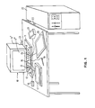
- Figure 1 is a schematic overall view of a display workstation embodying the present invention,
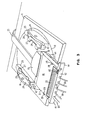
- Figure 2 is an external perspective view of the cable connector housing of figure 1, the housing being shown in its operative position between the tilt support brackets and with the image display device omitted,
- Figure 3 is a view similar to figure 2 but with the cable connector housing and released and slid forwardly from its operative position,
- Figure 4 is a perspective view of the cable connector housing with its lid open for the removal or insertion of peripheral input device cables,
- Figure 5 is a detailed top plan view of the cable connector housing,
- Figure 6 is a detailed bottom view of the cable connector housing,
- Figure 7 is a front view of the cable connector housing,
- Figure 8 is a cross-section taken on line 8-8 of figure 5, and
- Figure 9 is a cross-section taken on line 9-9 of figure 7.
- The display workstation, fig. 1, comprises a
display monitor 10 including an image display device 10', such as a CRT having aviewing screen 10", and abase 11 on which the device 10' is mounted by a tilt and swivel mechanism indicated generally at 12. The swivel motion, i.e., side to side rotation of the device 10' about a substantially vertical axis, is provided by aturntable 13 rotatably mounted in thebase 11 in a conventional manner. The tilt motion, i.e., forward and rearward rotation of the device 10' about a substantially horizontal axis, is provided by a pair of upstanding laterally spacedsupport brackets 14 mounted on theturntable 13 and a pair of cooperatingbrackets 15 which are fixed to and extend downwardly from the underside of the image display device 10'. - Between the
support brackets 14 thetilt mechanism base 11, and acable connector housing 16 is inserted into and releasably retained in this gap. Thehousing 16 is sufficiently shallow not to interfere with the tilt action of the device 10' within the angular range provided by the tilt mechanism. - The workstation is shown with a typical set of peripheral input devices such as an
alphanumeric keyboard 17,valuators 18, alight pen 19, a digitizing table 20 and a lighted programmed function keyboard (LPFK) 21. Each of these has an individual cable which extends to the front of and is releasably coupled to thehousing 16. - The workstation includes a
separate control unit 22, and a flat flexiblemulti-conductor cable 23 is coupled to the rear of thehousing 16 and extends therefrom to thecontrol unit 22. Thehousing 16 contains circuits which provide the desired electrical connections between the individual peripheral device cables and thecontrol unit cable 23, and serves as a power distribution and signal interface point. - Each
support bracket 14 has arecess 24, figs. 2 and 3, to accommodate arespective bracket 15 ot the image display device 10'. Eachrecess 24 includes a pair ofrollers 25 mounted respectively at the front and rear of therecess 24 to provide bearings for the lower surface of the respective bracket 15 (not shown in figs. 2 and 3). The lower surface of eachbracket 15 is arcuate and therefore the image display device 10' may be tilted forwardly and rearwardly by rotation of the arcuate surfaces of thebrackets 15 on theroller bearings 25. - The
housing 16 is of metal and comprises abase portion 30 and alid 31, fig. 4, thelid 31 being hinged to the rear of thebase portion 30 bypivot pins 32, figs. 4 and 5. In its operative position, fig. 2, thelid 31 of thehousing 16 is closed and the housing tits snugly between the parallel insidesurfaces 26 of thebrackets 14, and a pair of inwardly extendinglugs 27 on thebrackets 14 closely embrace the top surface of thehousing 16 along opposite side edges. Positive retention of thehousing 16 in this position is effected by a pair of spring-loadedcatches 28 which protrude upwardly throughrespective apertures 29 in the housing and engage behind the rear edge of theforemost lug 27 of each pair. Thehousing 16 is stabilized in its operative position against any slight movement in the front to rear direction by a pair ofcoil springs 40, fig. 6, thesprings 40 being retained behindlateral extensions 41 of thefront wall 42 of thelid 31 and being compressed against forward facingsurfaces 43 of thebrackets 14, fig. 3. Side to side stabilization is achieved by a pair of outwardly bowedleaf springs 44, figs 3 to 6, located along each side of thebase portion 30 and which bear against theparallel surfaces 26 on the inside of thebrackets 14. - The
catches 28 are pivoted at 34, figs. 5 and 8, to the sides of thelid 31 internally of thehousing 16 and arelease bar 33 extends across and is fixed to the upper edges of the catches. Therelease bar 33 and hence thecatches 28 are biassed upwardly by twoleaf springs 35 which bear on the underside of therelease bar 33 and are disposed one adjacent eachcatch 28. Thus thecatches 28 may be withdrawn into theapertures 29 by manual depression of therelease bar 33, which is exposed along the front edge of thehousing lid 31, whereby thehousing 16 may be slid forwardly from between thesupport brackets 14, fig. 3. Only when thehousing 16 is thus removed from between thebrackets 14 may thelid 31 be opened, fig. 4. - The four
peripheral device cables 50, figs. 2 and 3, for thevaluators 18,light pen 19,tablet 20 andLPFK 21 terminate inmulti-pin plugs 51, fig. 4, which plug intocorresponding sockets 52 mounted on a printed circuit board (PCB) 53 within thehousing 16. Eachcable 50 has acollar 54 moulded thereto adjacent theplug 51, eachcollar 54 having anannular groove 59. Thefront wall 42 of thelid 31 comprises a plurality ofvertical slots 55 with semicircular upper ends, figs. 2, 3 and 7, and thefront wall 56 of thebase portion 30 comprises a corresponding plurality ofsemicircular recesses 57, figs. 4 and 7. When thelid 31 is closed thefront wall 42 thereof overlaps thefront wall 56 of thebase portion 30 so that theslots 55 andrecesses 57 together define a plurality ofcircular apertures 58 in front of eachsocket 52. Theseapertures 58 engage thegroove 59 in eachcollar 54, as shown in fig. 9, thereby providing a positive retention or locking of eachcable 50 when thelid 31 is closed. - The
cable 60 from thealphanumeric keyboard 17 is thicker than thecables 50 and does not have acollar 54, thus itsaperture 58 is correspondingly larger as seen on the left in fig. 7. - The
cable 60 terminates in amulti-pin plug 61 which cooperates with acorresponding socket 62 mounted on the PCB 53. Since the direction of insertion of theplug 61 into thesocket 62 is parallel to the front of thehousing 16 thecable 60 is automatically retained in position when thelid 31 is closed. - Each
cable ground shield 65, fig. 4, of which a part is exposed adjacent therespective plug metal fuse clip 66 fixed to the inside surface of themetal base portion 30. Thetilt support brackets 14 are also metal, so that a ground connection is established via theclips 66,base portion 30 andsprings 44 to thebrackets 14. Thesebrackets 14 are in turn electrically connected to the main body of themonitor base 11, which is metal, and the latter is earthed. - The
control unit cable 23 is a multi-conductor flexible cable which both takes the signals from theperipheral input devices 17 to 21 to thecontrol unit 22, and also supplies power to these devices and to the circuits on thePCB 53. Thecable 23 terminates in twomulti-pin plugs 70 and 71, fig. 6, for signals out and power in respectively, and these plug intocorresponding sockets cable 23 enters thehousing 16 under arearwardly extending cover 75 integral with thebase portion 30, the cable being retained in position by ametal clamp 76 which makes electrical connection to an exposed portion of theground shield 77 of the cable. - The exact nature and function of the various
other circuit components 80, fig. 4, mounted on thePCB 53 is not critical to the present invention. At a minimum the circuitry on thePCB 53 will provide straight-through connections for the signals from theperipheral device cables control unit cable 23, and also supply power in the reverse direction to the peripheral input devices. However, it is preferable that the PCB circuitry also provide some signal processing in order to relieve thecontrol unit 22 of this task. Thus, since thealphanumeric keyboard 17 normally provides parallel signals, it is preferred that the PCB circuitry change these to serial format to correspond to the serial format of the signals from the other peripheral input devices. The manner in which such parallel-to-serial signal conversion may be performed is well known and does not need further description. ThePCB 53 also advantageously includes an audiblealarm volume control 81 with athumbwheel 82 which projects partially through the top of thehousing 16 through anaperture 83, see figs. 2, 3, and 5. - The cabling arrangement described above has significant advantages over prior systems:
- 1) It avoids a maze of cables on the desk top on which the monitor and peripheral input devices are located. This reduces the desk top space requirements and improves the ergonomics of the system hardware.
- 2) The ready attachment and detachment of cables permits user installation without significant effort and without the use of special tools. Faulty devices may also be readily replaced by the user.
- 3) The PCB in the cable connector housing provides for flexibility of peripheral input device configurations, since different configurations may be supported by changing the PCB circuitry. Alternatively, if the PCB circuitry includes a microprocessor, these changes may be supported by microcode change.
- 4) The metal housing provides isolation of the PCB circuitry from electromagnetic disturbances originating from the monitor and vice versa, and all peripheral devices are electrostatically grounded via the housing and monitor base.
- While, as described above, the invention is most effectively embodied in a monitor whose image display device is mounted on a separate base by a tilt mechanism having a pair of upstanding tilt support members with a gap between them, the advantages of the invention can also be obtained in the case of an image display device having an integral base, i.e., where the base in fact forms the lower part of the overall cabinet or housing of the monitor, and also in the case of a monitor whose tilt mechanism does not provide a gap as aforesaid or at least not a sufficient gap for the purpose required. In these cases, the base or monitor housing can be provided with a slot or recess below the viewing screen which is adapted to accommodate a cable connector housing similar to that described above. Furthermore, although the cable connector housing has been shown as releasably coupled to the base of the monitor, it could alternatively be releasably coupled to the underside of the image display device between the tilt support brackets.
Claims (8)
Applications Claiming Priority (2)
| Application Number | Priority Date | Filing Date | Title |
|---|---|---|---|
| US06/543,741 US4577187A (en) | 1983-10-20 | 1983-10-20 | Display workstation |
| US543741 | 1983-10-20 |
Publications (2)
| Publication Number | Publication Date |
|---|---|
| EP0140647A1 true EP0140647A1 (en) | 1985-05-08 |
| EP0140647B1 EP0140647B1 (en) | 1987-05-13 |
Family
ID=24169390
Family Applications (1)
| Application Number | Title | Priority Date | Filing Date |
|---|---|---|---|
| EP84307135A Expired EP0140647B1 (en) | 1983-10-20 | 1984-10-17 | Display workstation |
Country Status (4)
| Country | Link |
|---|---|
| US (1) | US4577187A (en) |
| EP (1) | EP0140647B1 (en) |
| JP (1) | JPS6098484A (en) |
| DE (1) | DE3463697D1 (en) |
Cited By (5)
| Publication number | Priority date | Publication date | Assignee | Title |
|---|---|---|---|---|
| FR2591056A1 (en) * | 1985-12-02 | 1987-06-05 | Cappagli Gerard | Interface module which can be embedded in a terminal |
| US4703412A (en) * | 1985-09-13 | 1987-10-27 | Lee Colortran, Inc. | Portable control unit for theater, television, and film lighting control systems |
| DE3740328A1 (en) * | 1987-11-27 | 1989-06-08 | Ralf M Gebhardt | Personal computer |
| GB2216692A (en) * | 1988-03-03 | 1989-10-11 | Bernard William Gill | Computer system layout |
| GB2270451A (en) * | 1992-09-03 | 1994-03-09 | Icl Personal Systems Oy | A microprocessor-controlled display unit |
Families Citing this family (22)
| Publication number | Priority date | Publication date | Assignee | Title |
|---|---|---|---|---|
| US4742473A (en) * | 1985-07-16 | 1988-05-03 | Shugar Joel K | Finite element modeling system |
| US4716542A (en) * | 1985-09-26 | 1987-12-29 | Timberline Software Corporation | Method and apparatus for single source entry of analog and digital data into a computer |
| JPS63170780A (en) * | 1986-10-03 | 1988-07-14 | インタランド・コーポレーション | Integrated multi-display type overlay control system communication work station |
| JPS6370765U (en) * | 1986-10-27 | 1988-05-12 | ||
| US4852500A (en) * | 1987-03-18 | 1989-08-01 | Herman Miller, Inc. | Integrated computer implement work area |
| US5174293A (en) * | 1988-11-17 | 1992-12-29 | Olympus Optical Co., Ltd. | Medical apparatus including on isolating transformer apparatus for isolating medical apparatus from non-medical apparatus to prevent electrical shocks to patients |
| US5589849A (en) * | 1989-07-03 | 1996-12-31 | Ditzik; Richard J. | Display monitor position adjustment apparatus |
| US5074511A (en) * | 1991-03-05 | 1991-12-24 | Wilson Lonnie L | Portable keyboard support |
| US5158257A (en) * | 1991-03-05 | 1992-10-27 | Wilson Lonnie L | Portable keyboard support |
| US5701347A (en) * | 1994-06-23 | 1997-12-23 | Compaq Computer Corporation | Audio system for a personal computer |
| US5633943A (en) * | 1994-09-09 | 1997-05-27 | Compaq Computer Corporation | Audio system for a personal computer |
| US6501836B1 (en) | 1994-09-09 | 2002-12-31 | Compaq Computer Corporation | Audio system for a personal computer |
| US5685441A (en) * | 1995-07-18 | 1997-11-11 | Vu Ryte, Inc. | Video display pedestal with article storage pockets |
| US5764479A (en) * | 1996-09-23 | 1998-06-09 | International Business Machines Corporation | Split system personal computer having floppy disk drive moveable between accessible and inaccessible positions |
| US7004613B2 (en) * | 2000-12-28 | 2006-02-28 | Au Optronics Corp. | Display structure |
| AUPR538401A0 (en) * | 2001-06-01 | 2001-06-28 | Khoury, Edward Joseph | Cordless base |
| US6851226B2 (en) * | 2002-02-15 | 2005-02-08 | Steelcase Development Corporation | Partition panel with modular appliance mounting arrangement |
| US20030222140A1 (en) * | 2002-06-04 | 2003-12-04 | Wasson Paul J. | Cash register assembly |
| US6987666B2 (en) * | 2003-03-26 | 2006-01-17 | Dell Products L.P. | Flat panel monitor stand |
| US7871300B2 (en) * | 2007-01-04 | 2011-01-18 | Whirlpool Corporation | Host with multiple sequential adapters for multiple consumer electronic devices |
| TWM405129U (en) * | 2010-12-29 | 2011-06-01 | Kimo Nat Co Ltd | Hidden structure for combination of 3C product and transmission line |
| US10785886B2 (en) * | 2015-10-13 | 2020-09-22 | Braun Research Corporation | System, apparatus, and method for providing a programmable logic controller |
Citations (8)
| Publication number | Priority date | Publication date | Assignee | Title |
|---|---|---|---|---|
| DE2938426A1 (en) * | 1979-09-22 | 1981-04-09 | Wolfgang Ing Grad Ferenz | Switching network control panel - combines conductive chart and contact prod. with visual display and pushbutton panel, and includes coordinate setter |
| EP0046225A2 (en) * | 1980-08-20 | 1982-02-24 | Siemens Aktiengesellschaft | Device for mounting a display unit on a working area |
| EP0058242A1 (en) * | 1981-02-16 | 1982-08-25 | Siemens Aktiengesellschaft | Visual data display unit |
| EP0068891A1 (en) * | 1981-06-29 | 1983-01-05 | Honeywell Information Systems Inc. | CRT display terminal with modular design |
| EP0068890A1 (en) * | 1981-06-29 | 1983-01-05 | Honeywell Information Systems Inc. | Power supply module in CRT display terminal |
| EP0068889A1 (en) * | 1981-06-29 | 1983-01-05 | Bull HN Information Systems Inc. | Adjustable mounting in CRT device |
| EP0078895A1 (en) * | 1981-11-05 | 1983-05-18 | GRUNDIG E.M.V. Elektro-Mechanische Versuchsanstalt Max Grundig holländ. Stiftung & Co. KG. | Television set |
| EP0087948A2 (en) * | 1982-02-27 | 1983-09-07 | Fanuc Ltd. | Method and apparatus for creating part program data |
Family Cites Families (15)
| Publication number | Priority date | Publication date | Assignee | Title |
|---|---|---|---|---|
| GB1299882A (en) * | 1969-01-24 | 1972-12-13 | Ernest F Moy Ltd | Tilt table device |
| US3809395A (en) * | 1972-09-28 | 1974-05-07 | Magnavox Co | Television combat game |
| US4064560A (en) * | 1975-07-25 | 1977-12-20 | Bunker Ramo Corporation | Master keyboard terminal with auxiliary keyboard terminal capability |
| US4306232A (en) * | 1977-04-06 | 1981-12-15 | Texas Instruments Incorporated | Digital joystick control interface system for video games and the like |
| US4259668A (en) * | 1978-05-15 | 1981-03-31 | Sharp Kabushiki Kaisha | Television set/calculator interface including exchangeable keyboard panel and program memory cartridge |
| US4208081A (en) * | 1979-01-03 | 1980-06-17 | International Business Machines Corporation | Easily reconfigurable data entry terminal |
| US4326193A (en) * | 1979-09-12 | 1982-04-20 | Allen-Bradley Company | Terminal with interchangeable application module |
| US4313112A (en) * | 1979-12-17 | 1982-01-26 | Foster Daniel F | Computer work station assembly and mounting apparatus therefor |
| US4330776A (en) * | 1980-03-04 | 1982-05-18 | Instrumentation Laboratory Inc. | Keyboard type of input control system for an analytical instrument |
| US4349173A (en) * | 1980-06-24 | 1982-09-14 | Burroughs Corporation | Tilt device for use with cathode ray tube display units |
| US4451701A (en) * | 1980-10-30 | 1984-05-29 | Oclc Online Computer Library Center, Incorporated | Viewdata system and apparatus |
| US4410159A (en) * | 1981-07-14 | 1983-10-18 | Sperry Corporation | Adjustable support for a video display terminal |
| DE3132015A1 (en) * | 1981-08-13 | 1982-10-28 | Daimler-Benz Ag, 7000 Stuttgart | Arrangement of a visual display unit at workplaces consisting of a plurality of desks or the like which have been placed together |
| JPS5857181A (en) * | 1981-09-30 | 1983-04-05 | 富士通株式会社 | Vertical angle varying mechanism |
| US4496200A (en) * | 1982-09-30 | 1985-01-29 | Teletype Corporation | Desk top keyboard display terminal with an articulated keyboard |
-
1983
- 1983-10-20 US US06/543,741 patent/US4577187A/en not_active Expired - Fee Related
-
1984
- 1984-07-13 JP JP59144583A patent/JPS6098484A/en active Granted
- 1984-10-17 DE DE8484307135T patent/DE3463697D1/en not_active Expired
- 1984-10-17 EP EP84307135A patent/EP0140647B1/en not_active Expired
Patent Citations (8)
| Publication number | Priority date | Publication date | Assignee | Title |
|---|---|---|---|---|
| DE2938426A1 (en) * | 1979-09-22 | 1981-04-09 | Wolfgang Ing Grad Ferenz | Switching network control panel - combines conductive chart and contact prod. with visual display and pushbutton panel, and includes coordinate setter |
| EP0046225A2 (en) * | 1980-08-20 | 1982-02-24 | Siemens Aktiengesellschaft | Device for mounting a display unit on a working area |
| EP0058242A1 (en) * | 1981-02-16 | 1982-08-25 | Siemens Aktiengesellschaft | Visual data display unit |
| EP0068891A1 (en) * | 1981-06-29 | 1983-01-05 | Honeywell Information Systems Inc. | CRT display terminal with modular design |
| EP0068890A1 (en) * | 1981-06-29 | 1983-01-05 | Honeywell Information Systems Inc. | Power supply module in CRT display terminal |
| EP0068889A1 (en) * | 1981-06-29 | 1983-01-05 | Bull HN Information Systems Inc. | Adjustable mounting in CRT device |
| EP0078895A1 (en) * | 1981-11-05 | 1983-05-18 | GRUNDIG E.M.V. Elektro-Mechanische Versuchsanstalt Max Grundig holländ. Stiftung & Co. KG. | Television set |
| EP0087948A2 (en) * | 1982-02-27 | 1983-09-07 | Fanuc Ltd. | Method and apparatus for creating part program data |
Non-Patent Citations (1)
| Title |
|---|
| IEEE TRANSACTIONS ON COMMUNICATIONS, vol. COM-31, no. 2, February 1983, pages 245-250, IEEE, New York, US; R.D. GORDON: "An interactive video information terminal" * |
Cited By (7)
| Publication number | Priority date | Publication date | Assignee | Title |
|---|---|---|---|---|
| US4703412A (en) * | 1985-09-13 | 1987-10-27 | Lee Colortran, Inc. | Portable control unit for theater, television, and film lighting control systems |
| FR2591056A1 (en) * | 1985-12-02 | 1987-06-05 | Cappagli Gerard | Interface module which can be embedded in a terminal |
| DE3740328A1 (en) * | 1987-11-27 | 1989-06-08 | Ralf M Gebhardt | Personal computer |
| GB2216692A (en) * | 1988-03-03 | 1989-10-11 | Bernard William Gill | Computer system layout |
| GB2216692B (en) * | 1988-03-03 | 1992-06-03 | Bernard William Gill | Computer system layout |
| GB2270451A (en) * | 1992-09-03 | 1994-03-09 | Icl Personal Systems Oy | A microprocessor-controlled display unit |
| GB2270451B (en) * | 1992-09-03 | 1996-02-07 | Icl Personal Systems Oy | A microprocessor-controlled display unit |
Also Published As
| Publication number | Publication date |
|---|---|
| DE3463697D1 (en) | 1987-06-19 |
| EP0140647B1 (en) | 1987-05-13 |
| JPH0159592B2 (en) | 1989-12-18 |
| US4577187A (en) | 1986-03-18 |
| JPS6098484A (en) | 1985-06-01 |
Similar Documents
| Publication | Publication Date | Title |
|---|---|---|
| US4577187A (en) | Display workstation | |
| US5231562A (en) | Desk top wire management apparatus | |
| US5815735A (en) | Portable computer with removable display screen using removably mateable connectors to form the sole supporting interconnection between the computer base portion and display screen structure | |
| US5808860A (en) | Portable electronic apparatus with detachably mounted keyboard | |
| US5050041A (en) | Modem mountable in wall of a computer housing with readily accessible, on/off switch, indicator means and internal switch connecting either modem or an auxiliary serial port to an I/O port | |
| US5822185A (en) | Ergonomic docking station for a portable computer | |
| JPH04232084A (en) | Method and device for mounting printer | |
| US4530066A (en) | Compact expandable electronic signal processing apparatus | |
| EP0437370A1 (en) | Terminal device having cable routing means | |
| US5546334A (en) | Notebook computer system with a separable trackball | |
| US5249103A (en) | Modular transaction terminal having a docking surface with a plurality of parallel grooves | |
| US6560094B2 (en) | Mounting device for a monitor, a flat monitor with such a mounting device, and an assembly of a flat monitor, a drawer and a computer | |
| TW286377B (en) | ||
| US6129429A (en) | Rack serviceable computer chassis assembly | |
| WO2002082213A2 (en) | Portable computer | |
| KR930003405B1 (en) | Cordless computer assembly | |
| CA2011426A1 (en) | Docking module | |
| US4958889A (en) | Three-position closure panel | |
| JP4672235B2 (en) | Desk and desk system | |
| US5493542A (en) | Arrangement for portable computers | |
| US20070064096A1 (en) | Roll over audio visual control center | |
| US6950311B1 (en) | Telecommunications switch/server | |
| JPH08505486A (en) | Microcomputer with computer case, control case, monitor and keyboard | |
| KR930005834B1 (en) | Portable pc | |
| US11477895B2 (en) | Modular KMM system having removable KMM console |
Legal Events
| Date | Code | Title | Description |
|---|---|---|---|
| PUAI | Public reference made under article 153(3) epc to a published international application that has entered the european phase |
Free format text: ORIGINAL CODE: 0009012 |
|
| 17P | Request for examination filed |
Effective date: 19841123 |
|
| AK | Designated contracting states |
Designated state(s): DE FR GB |
|
| 17Q | First examination report despatched |
Effective date: 19860203 |
|
| GRAA | (expected) grant |
Free format text: ORIGINAL CODE: 0009210 |
|
| AK | Designated contracting states |
Kind code of ref document: B1 Designated state(s): DE FR GB |
|
| REF | Corresponds to: |
Ref document number: 3463697 Country of ref document: DE Date of ref document: 19870619 |
|
| ET | Fr: translation filed | ||
| PLBE | No opposition filed within time limit |
Free format text: ORIGINAL CODE: 0009261 |
|
| STAA | Information on the status of an ep patent application or granted ep patent |
Free format text: STATUS: NO OPPOSITION FILED WITHIN TIME LIMIT |
|
| 26N | No opposition filed | ||
| PGFP | Annual fee paid to national office [announced via postgrant information from national office to epo] |
Ref country code: GB Payment date: 19910923 Year of fee payment: 8 |
|
| PGFP | Annual fee paid to national office [announced via postgrant information from national office to epo] |
Ref country code: FR Payment date: 19911001 Year of fee payment: 8 |
|
| PGFP | Annual fee paid to national office [announced via postgrant information from national office to epo] |
Ref country code: DE Payment date: 19911102 Year of fee payment: 8 |
|
| PG25 | Lapsed in a contracting state [announced via postgrant information from national office to epo] |
Ref country code: GB Effective date: 19921017 |
|
| GBPC | Gb: european patent ceased through non-payment of renewal fee |
Effective date: 19921017 |
|
| PG25 | Lapsed in a contracting state [announced via postgrant information from national office to epo] |
Ref country code: FR Effective date: 19930630 |
|
| PG25 | Lapsed in a contracting state [announced via postgrant information from national office to epo] |
Ref country code: DE Effective date: 19930701 |
|
| REG | Reference to a national code |
Ref country code: FR Ref legal event code: ST |