EP0140436B1 - Frame for door or window opening - Google Patents
Frame for door or window opening Download PDFInfo
- Publication number
- EP0140436B1 EP0140436B1 EP84201465A EP84201465A EP0140436B1 EP 0140436 B1 EP0140436 B1 EP 0140436B1 EP 84201465 A EP84201465 A EP 84201465A EP 84201465 A EP84201465 A EP 84201465A EP 0140436 B1 EP0140436 B1 EP 0140436B1
- Authority
- EP
- European Patent Office
- Prior art keywords
- clamping
- profile
- rims
- clamping jaws
- frame
- Prior art date
- Legal status (The legal status is an assumption and is not a legal conclusion. Google has not performed a legal analysis and makes no representation as to the accuracy of the status listed.)
- Expired
Links
Images


Classifications
-
- E—FIXED CONSTRUCTIONS
- E06—DOORS, WINDOWS, SHUTTERS, OR ROLLER BLINDS IN GENERAL; LADDERS
- E06B—FIXED OR MOVABLE CLOSURES FOR OPENINGS IN BUILDINGS, VEHICLES, FENCES OR LIKE ENCLOSURES IN GENERAL, e.g. DOORS, WINDOWS, BLINDS, GATES
- E06B1/00—Border constructions of openings in walls, floors, or ceilings; Frames to be rigidly mounted in such openings
- E06B1/56—Fastening frames to the border of openings or to similar contiguous frames
- E06B1/60—Fastening frames to the border of openings or to similar contiguous frames by mechanical means, e.g. anchoring means
- E06B1/6046—Clamping means acting perpendicular to the wall opening; Fastening frames by tightening or drawing them against a surface parallel to the opening
- E06B1/6061—Clamping means acting perpendicular to the wall opening; Fastening frames by tightening or drawing them against a surface parallel to the opening with separate clamping means acting on opposite wall or associated surfaces
-
- E—FIXED CONSTRUCTIONS
- E05—LOCKS; KEYS; WINDOW OR DOOR FITTINGS; SAFES
- E05D—HINGES OR SUSPENSION DEVICES FOR DOORS, WINDOWS OR WINGS
- E05D5/00—Construction of single parts, e.g. the parts for attachment
- E05D5/02—Parts for attachment, e.g. flaps
- E05D5/0215—Parts for attachment, e.g. flaps for attachment to profile members or the like
- E05D5/0223—Parts for attachment, e.g. flaps for attachment to profile members or the like with parts, e.g. screws, extending through the profile wall or engaging profile grooves
- E05D5/0238—Parts for attachment, e.g. flaps for attachment to profile members or the like with parts, e.g. screws, extending through the profile wall or engaging profile grooves with parts engaging profile grooves
-
- E—FIXED CONSTRUCTIONS
- E05—LOCKS; KEYS; WINDOW OR DOOR FITTINGS; SAFES
- E05D—HINGES OR SUSPENSION DEVICES FOR DOORS, WINDOWS OR WINGS
- E05D7/00—Hinges or pivots of special construction
- E05D7/04—Hinges adjustable relative to the wing or the frame
-
- E—FIXED CONSTRUCTIONS
- E05—LOCKS; KEYS; WINDOW OR DOOR FITTINGS; SAFES
- E05Y—INDEXING SCHEME RELATING TO HINGES OR OTHER SUSPENSION DEVICES FOR DOORS, WINDOWS OR WINGS AND DEVICES FOR MOVING WINGS INTO OPEN OR CLOSED POSITION, CHECKS FOR WINGS AND WING FITTINGS NOT OTHERWISE PROVIDED FOR, CONCERNED WITH THE FUNCTIONING OF THE WING
- E05Y2900/00—Application of doors, windows, wings or fittings thereof
- E05Y2900/10—Application of doors, windows, wings or fittings thereof for buildings or parts thereof
- E05Y2900/13—Application of doors, windows, wings or fittings thereof for buildings or parts thereof characterised by the type of wing
- E05Y2900/148—Windows
Definitions
- the invention relates to a frame as defined in the heading of claim I.
- Such a frame is known from BE 890707.
- the clamping jaws grip by their own spring force the bent-over rims of the frame profile.
- the frame may shift in place with respect to the wall.
- the connection is so weak that a large number of clamps distributed along the circumference of the frame is required.
- the invention provides such a strong clamp that by means of few clamps distributed along the circumference of the frame a firm connection of the frame with the wall can be ensured thanks to the characteristic feature defined in claim 1. Even the clamps themselves require little material because the clamping jaws can be made from thin steel sheet. This is preferably high-quality steel.
- the frame as disclosed in US 3248833 has clamping devices of another kind, each having two clamping jaw elements guided in guides welded to the frame profile.
- the two clamping jaw elements are fixed to the profile rims, but they do not support against each other at a pivot place and they are not interconnected at a pivot place. Said two clamping jaw elements are tensioned without engaging each other.
- the clamping jaw elements are guided by guide plates welded to the profile.
- the hand force for tensioning the clamping device is for a great deal used for overcoming the friction forces at the guiding plates due to jamming clamping jaw-elements. It is not easy with normal hand power to connect the frame rigidly onto a wall rim with a small number of clamping devices.
- US-A-3352074 discloses a frame with clamping devices each having two clamping jaw elements to be tensioned by means of a screw bolt, the free ends of said clamping jaw elements engaging U-shaped profile rims, a fulcrum block being provided at the profile between the two separate clamping jaw elements.
- the clamping jaw elements do not hook one into the other and are not fixed to profile rims extending transversely onto the wall plane in an anchoring manner.
- DE-A-2.913.363 discloses a frame having clamping devices, each comprising a screw bolt
- the U-shaped clamping element is elastically deformable like the one of BE-A-890707.
- the two pulling members hook into the clamping element with clearance.
- the ends of the clamping element engage U-shaped profile rims.
- the clamping jaw would be rigidly connected, e.g. by welding to the profile rims, it would be impossible to deform the profile during the operation bringing the profile onto a wall rim.
- AT-A-340660 discloses a wooden frame being connected to a wall by means of clamping devices each comprising a clamping jaw element being profiled in its longitudinal direction and being tensioned by means of a screw bolt. This clamping jaw element being guided between said screw bolt and a support element.
- FR-A-2264952 discloses with reference to figs. 4 and 7 a clamping device used for connection of a paumelle at the exterior of a frame profile, said clamping device comprising a clamping jaw element hooking into another clamping jaw- element and being clamped by means of a screw bolt.
- FR-A-2526846 disclosing a frame with clamping devices having two clamping jaws forming part of one and the same U-shaped clamping element of metal plate, a screw bolt being arranged at the exterior of said U-shaped clamping element between a console and a free end of a protrusion arranged at the exterior of the clamping jaw element.
- a rigid clamping connection can not be obtained by means of this clamping device due to the slack construction of the clamping jaw element and due to the absence of anchoring action.
- the invention also provides a frame as described in claim 5.
- the screw bolt can be arranged at a considerable distance from the pivot place of the clamping device in order to use the tensioning force of the screw bolt efficiently, whereby the clamping jaw elements are so rigidly constructed that they can transfer such great clamping forces onto the profile rims.
- Fig. 1 shows a wall 1, on which is mounted a frame element 50, for example, a jamb or a lintel of a door, said frame element 40 comprising a profile 2 having a substantially U-shaped cross-section.
- the bottom 3 of the U constitutes the visible side of the profile 2, whereas the limbs of the U constitute flanges 4 and 5, whose rims 6 and 7 clamp a wall rim 1 in between them.
- the flange rims 6, 7 and the flanges 4, 5 are inwardly bent over and are transverse, preferably perpendicular to the plane 32 of the wall.
- a clamping device 8 Inside the profile 2 is arranged a clamping device 8 having two cooperating clampings jaws 9 and 10.
- the two clamping jaws 9 10 each have a bent-over head rim 11 and 12 respectively, which are welded to the flange rim 6 and 7 respectively of the profile 2 in the factory, at least prior to mounting the frame element 40 to the wall rim I.
- the clamping jaw 9 extends from the head rim 11 by a part 13 along the flange 4 and is prolonged by a part 14 extending in the direction to the bottom 3 of the profile 2, which part is followed by a part 15, which is substantially parallel to the part 13 and is prolonged in a part 16 extending substantially parallel to the bottom 3 of the profile.
- the clamping jaw 10 extends from the head rim 12 along substantially the whole flange 5 and has a countersunk portion 17 to which a nut 18 is fastened, for example, welded. Instead of using a nut 27 the clamping jaw 10 may have a tapped hole.
- the clamping jaw 9 has in the part 15 an opening 19, through which is passed a hollow screw 20, which is screwed into the pressed-in nut 18 and forms part of clamping means drawing the two clamping jaws 9 and 10 towards one another.
- the free end of the part 16 of the clamping jaw 9 is provided with a tag 21 which is substantially in line with the part 16 and which grips with a large amount of clearance into an opening 22 near the free end of the clamping jaw 10. Owing to said clearance the tag 21 is displaceable in the opening 22 in a direction transverse of the part 16, whilst the clamping jaws 9 and 10 are pivotable relatively to one another.
- the two clamping jaws 9 and 10 are each provided along their two side edges with stiffening ridges 23, 24 and 25, 25 respectively covering substantially the entire length. These stiffening ridges continue along the bent-over head rims 11 and 12 of the two clamping jaws 9 and 10 and have bulging parts 28 in these head rims 11 and 12 to serve as projections in projection welding for establishing the welding junction of these head rims with the associated flange rims 6 and 7 of the profile 2.
- Fig. 5 schematically shows a detail of the clamping device 8 illustrating the movabilities of the two clamping jaws 9 and 10 relative to one another.
- the position of the clamping jaws 9 and 10 indicated by solid lines is occupied when the hollow screw 20 is tightened.
- the clamping jaws 9 and 10 then turn towards one another about the head rim 33 of the part 16 engaging the clamping jaw 10.
- the two flanges 4 and 5 are then moved along by the two clamping jaws 9 and 10 and firmly urged with their flange rims 6 and 7 respectively against the said faces 32 of the wall rim 1 so that a satisfactory connection of the frame element 40 is obtained.
- the bolt 20 is loosely screwed into the nut 18 and the two clamping jaws 9 and 10 are relatively movable. If, for example, the wall rim is somewhat thicker the flanges 4 and 5 of the profile 2 must be pushed away one from the other to permit of sliding the profile 2 around the wall rim 1. During this deflection of the flanges 4 5 the clamping jaw 9 will perform a rotation about the area where the bolt 20 is passed through the opening 19 with an amount of clearance. The part 16 of the clamping jaw 9 will then move in the direction of the arrow R into the position indicated by solid lines.
- the two clamping jaws 9 and 10 can thus readily move with respect to one another so that the frame element 40 can be arranged around the wall rim 1 with ample clearance and little deformation.
- the hollow screw 20 can be readily actuated through an opening 29 in a groove 34 of the profile 2, which opening can be closed by means of a rubber plug 30 or a synthetic resin cover.
- Figs. 6 and 7 show a frame element 40 embodying the invention which is particularly effective on smooth and/or shrinkable walls.
- the head rims 11, 12 of the two clamping jaws 9 and 10 are provided between the spaces 46 formed by the stiffening ridges 25 and 26 with an anchoring plate 31, which slightly projects in the mounted state out of the bent-over head rims 6, 7 of the flanges.
- the edges 47 of the anchoring plates 1 projecting beyond the head rims 6, 7 may be sharp or serrated.
- these anchoring plates 31 may be made from hard steel and be loosely slopped into said spaces so that in the mounted state they slightly penetrate into the wall rim 1 and thus additionally anchor the frame element 40.
- the nut 27 can be constituted by an element welded to a clamping jaw 9 or can be constituted by a part of the clamping jaw 9 having screw tapped hole.
- the nut 27 is not utilized. Yet it is preferred to provide such a nut 27 in order to render the clamping device 8 universally usable, that is to say also for the purpose described hereinafter with reference to Fig. 10.
- the nut 27 constitutes a paumelle fastening means for fastening a wing 42 of a paumelle 43.
- a ridge 50 of the wing 42 of the hinge 43 is enclosed between the two stiffening ridges 23 and 24 and, owing to a slot 41 in the wing 42 of a paumelle 43 it can be adjustably fixed in place in the direction of length of these stiffening ridges by means of a hollow screw 45, which is accessible through a hole 48 in the profile 2 with the aid of a key adapted to the hollow head of the hollow screw 55.
- the paumelle 43 is fastened to the rugged clamping device 8 clamping tightly to the wall rim 1 instead of being fastened to the relatively slack metal of the profile 2 so that the forces exerted on the paumelle 43 are transferred through the clamping device 8 to the wall rim 1, as a result of which the load on the profile 2 is reduced and the profile may, if desired, be made from thinner sheet material.
- the forces exerted on the paumelle 53 are transferred through the tag 21 and the bolt 20 of the clamping jaw 9 to the clamping jaw 10.
- the tag 21 ensures that the two clamping jaws 9 and 10 will invariably be in the correct relative positions.
- the hole 48 can be closed with a synthetic resin cover 49.
- the depressed ridge 50 in the middle of the wing 42 of the paumelle imparts rigidity to this wing 42. Moreover owing to the adaptation of this ridge shape of the wing 42 to the gutter shape of the profile 2 of the part 14 of the clamping jaw 9 a firm interengagement of the paumelle 43 and the clamping jaw 9 is ensured.
- the wing 42 of the paumelle 43 passes through a passage 51 recessed in the flange 4 and matching the section of the wing 42 which is asymmetrical to rotation. This means that the opening 51 permits only in one position of slipping in the wing 42 from the outside, in which position a cam 52 engages the groove 53 in the wing 42 on the side opposite the ridge 50.
- the frame element 69 of Fig. 11 corresponds with that of Fig. 10, the difference being that the clamping jaw 71 pivotally bears by its free end 72 on a central part 73 of the clamping jaw 74 and extends by a hook-like tag 75 through an opening 76 of the central part 73.
- a console 78 To the clamping jaw 71 is welded a console 78 to which is welded a nut 18.
- the nut 18 with the hollow screw 20 constitutes the means for stretching the clamping device 80, whilst the hollow screw 20 bears on the free end 77 of the clamping jaw 74.
- the frame element 85 of Fig. 12 corresponds with that of Fig. 11, the difference being that the clamping jaw 81 consists of two plate portions 82 and 83, which are welded to one another at their free ends 84 after being depressed to form rigid elements for constituting a console 86, to which a nut 18 is welded.
- Fig. 13 is distinguished from Fig. 10 in that the head rims 91 of the clamping jaws 92 and 93 are not welded to the flange rims 84. Instead the flange rims 94 each have a bent-over rim 95, which is parallel to the surface 32 of the wall rim 1.
- the clamping device 97 When the clamping device 97 is stretched, the head rims 91 of the clamping jaws 92 and 93 clamp the bent-over rims 95 against the wall rim 1 so that the frame element 40 is tightly clamped to the wall rim 1.
- the sectional views to XIV to XVIII show a profile of the clamping jaws 9 and 10 in which upright gutter sides 97 of a gutter profile 98 adjoin flanges 99 so that each clamping jaw 9,10 derives its rigidity despite the small thickness of the material mainly from said gutter profile 98.
- the flanges 99 may have downwardly bent-over rims.
- the clamping jaws 9, 20 are preferably made from high-grade steel so that with a heavy stamping force they can just be bent and profiled. The process of profiling with heavy stamping force increases highly the rigidity of the material so that the clamping jaws 9, 10 become very rigid.
- the clamping jaws may be subjected to a hardening process.
- the thickness d of the material of the clamping jaws 9,10 is preferably less than 2 mms.
Description
- The invention relates to a frame as defined in the heading of claim I.
- Such a frame is known from BE 890707. In this case the clamping jaws grip by their own spring force the bent-over rims of the frame profile. In the event of shocks and particularly of vibrations the frame may shift in place with respect to the wall. The connection is so weak that a large number of clamps distributed along the circumference of the frame is required.
- The invention provides such a strong clamp that by means of few clamps distributed along the circumference of the frame a firm connection of the frame with the wall can be ensured thanks to the characteristic feature defined in claim 1. Even the clamps themselves require little material because the clamping jaws can be made from thin steel sheet. This is preferably high-quality steel.
- The frame as disclosed in US 3248833 has clamping devices of another kind, each having two clamping jaw elements guided in guides welded to the frame profile. The two clamping jaw elements are fixed to the profile rims, but they do not support against each other at a pivot place and they are not interconnected at a pivot place. Said two clamping jaw elements are tensioned without engaging each other. The clamping jaw elements are guided by guide plates welded to the profile. The hand force for tensioning the clamping device is for a great deal used for overcoming the friction forces at the guiding plates due to jamming clamping jaw-elements. It is not easy with normal hand power to connect the frame rigidly onto a wall rim with a small number of clamping devices.
- US-A-3352074 discloses a frame with clamping devices each having two clamping jaw elements to be tensioned by means of a screw bolt, the free ends of said clamping jaw elements engaging U-shaped profile rims, a fulcrum block being provided at the profile between the two separate clamping jaw elements. The clamping jaw elements do not hook one into the other and are not fixed to profile rims extending transversely onto the wall plane in an anchoring manner.
- DE-A-2.913.363 discloses a frame having clamping devices, each comprising a screw bolt;
- two clamping jaws forming part of one and the same U-shaped clamping element;
- and two pulling members.
- The U-shaped clamping element is elastically deformable like the one of BE-A-890707. The two pulling members hook into the clamping element with clearance. The ends of the clamping element engage U-shaped profile rims. In case the clamping jaw would be rigidly connected, e.g. by welding to the profile rims, it would be impossible to deform the profile during the operation bringing the profile onto a wall rim.
- AT-A-340660 discloses a wooden frame being connected to a wall by means of clamping devices each comprising a clamping jaw element being profiled in its longitudinal direction and being tensioned by means of a screw bolt. This clamping jaw element being guided between said screw bolt and a support element.
- FR-A-2264952 discloses with reference to figs. 4 and 7 a clamping device used for connection of a paumelle at the exterior of a frame profile, said clamping device comprising a clamping jaw element hooking into another clamping jaw- element and being clamped by means of a screw bolt.
- Relating to claim 3 reference is made to FR-A-2526846 disclosing a frame with clamping devices having two clamping jaws forming part of one and the same U-shaped clamping element of metal plate, a screw bolt being arranged at the exterior of said U-shaped clamping element between a console and a free end of a protrusion arranged at the exterior of the clamping jaw element. A rigid clamping connection can not be obtained by means of this clamping device due to the slack construction of the clamping jaw element and due to the absence of anchoring action.
- The invention also provides a frame as described in
claim 5. In this embodiment the screw bolt can be arranged at a considerable distance from the pivot place of the clamping device in order to use the tensioning force of the screw bolt efficiently, whereby the clamping jaw elements are so rigidly constructed that they can transfer such great clamping forces onto the profile rims. - The above mentioned and furtherfeatures of the invention are elucidated in the following description with reference to a drawing.
- The drawing schematically shows in
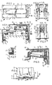
- Fig. 1 a cross-sectional view of a frame element embodying the invention mounted in a wall opening,
- Fig. 2 a plan view of a clamping device of the frame element of Fig. 1,
- Fig. 3 an elevational view of a clamping jaw of the clamping device of Fig. 2 taken in the direction of the arrows III-III in Fig. 2,
- Fig. 4 an elevational view of a further clamping jaw of the clamping device of Fig. 2 taken in the direction of the arrows IV-IV in Fig. 2,
- Fig. 5 a detail of the clamping device of Fig. 2 illustrating the co-operation between the two clamping jaws,
- Fig. 6 an enlarged elevational view of the end part of a clamping jaw connected with a flange rim of the profile,
- Fig. 7 a sectional view taken on the line VII-VII in Fig. 6,
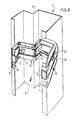
- Figs. 8 and 9 two different perspective views of the frame element shown in Fig. 7 in accordance with the invention,
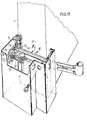
- Fig. 10 an elevational view like Fig. 9, where a paumelle is arranged on the clamping device,
- Figs. 11 to 13 elevational views like Fig. 10 of different frame elements embodying the invention, and
- Figs. 14-18 each a sectional view on the lines XIV-XIV to XVIII-XVIII respectively in Fig. 1.
- Fig. 1 shows a wall 1, on which is mounted a
frame element 50, for example, a jamb or a lintel of a door, saidframe element 40 comprising aprofile 2 having a substantially U-shaped cross-section. Thebottom 3 of the U constitutes the visible side of theprofile 2, whereas the limbs of the U constituteflanges 4 and 5, whoserims flanges 4, 5 are inwardly bent over and are transverse, preferably perpendicular to theplane 32 of the wall. Inside theprofile 2 is arranged aclamping device 8 having two cooperatingclampings jaws clamping jaws 9 10 each have a bent-overhead rim 11 and 12 respectively, which are welded to theflange rim profile 2 in the factory, at least prior to mounting theframe element 40 to the wall rim I. - The
clamping jaw 9 extends from the head rim 11 by apart 13 along the flange 4 and is prolonged by apart 14 extending in the direction to thebottom 3 of theprofile 2, which part is followed by apart 15, which is substantially parallel to thepart 13 and is prolonged in apart 16 extending substantially parallel to thebottom 3 of the profile. - The
clamping jaw 10 extends from thehead rim 12 along substantially thewhole flange 5 and has a countersunk portion 17 to which anut 18 is fastened, for example, welded. Instead of using anut 27 theclamping jaw 10 may have a tapped hole. Theclamping jaw 9 has in thepart 15 an opening 19, through which is passed ahollow screw 20, which is screwed into the pressed-innut 18 and forms part of clamping means drawing the twoclamping jaws - The free end of the
part 16 of theclamping jaw 9 is provided with atag 21 which is substantially in line with thepart 16 and which grips with a large amount of clearance into an opening 22 near the free end of theclamping jaw 10. Owing to said clearance thetag 21 is displaceable in the opening 22 in a direction transverse of thepart 16, whilst theclamping jaws - The two
clamping jaws stiffening ridges head rims 11 and 12 of the twoclamping jaws parts 28 in thesehead rims 11 and 12 to serve as projections in projection welding for establishing the welding junction of these head rims with the associatedflange rims profile 2. - Fig. 5 schematically shows a detail of the
clamping device 8 illustrating the movabilities of the twoclamping jaws clamping jaws hollow screw 20 is tightened. The clampingjaws head rim 33 of thepart 16 engaging theclamping jaw 10. The twoflanges 4 and 5 are then moved along by the twoclamping jaws flange rims faces 32 of the wall rim 1 so that a satisfactory connection of theframe element 40 is obtained. - Before the
frame element 40 is mounted on the wall rim 1 thebolt 20 is loosely screwed into thenut 18 and the twoclamping jaws flanges 4 and 5 of theprofile 2 must be pushed away one from the other to permit of sliding theprofile 2 around the wall rim 1. During this deflection of the flanges 4 5 theclamping jaw 9 will perform a rotation about the area where thebolt 20 is passed through theopening 19 with an amount of clearance. Thepart 16 of theclamping jaw 9 will then move in the direction of the arrow R into the position indicated by solid lines. This movability of theclamping jaw 9 with respect to theclamping jaw 10 is limited by the opening 22 in which thetag 21 is engaged. The two clampingjaws frame element 40 can be arranged around the wall rim 1 with ample clearance and little deformation. Thehollow screw 20 can be readily actuated through an opening 29 in agroove 34 of theprofile 2, which opening can be closed by means of arubber plug 30 or a synthetic resin cover. - Figs. 6 and 7 show a
frame element 40 embodying the invention which is particularly effective on smooth and/or shrinkable walls. The head rims 11, 12 of the two clampingjaws spaces 46 formed by the stiffeningridges plate 31, which slightly projects in the mounted state out of the bent-overhead rims edges 47 of the anchoring plates 1 projecting beyond the head rims 6, 7 may be sharp or serrated. If desired, these anchoringplates 31 may be made from hard steel and be loosely slopped into said spaces so that in the mounted state they slightly penetrate into the wall rim 1 and thus additionally anchor theframe element 40. - Between the two stiffening
ridges part 14 of the clampingjaw 9 has fastened to it anut 27. Thenut 27 can be constituted by an element welded to aclamping jaw 9 or can be constituted by a part of the clampingjaw 9 having screw tapped hole. For the use illustrated in Figs. 8 and 9 thenut 27 is not utilized. Yet it is preferred to provide such anut 27 in order to render theclamping device 8 universally usable, that is to say also for the purpose described hereinafter with reference to Fig. 10. - The
nut 27 constitutes a paumelle fastening means for fastening awing 42 of apaumelle 43. Aridge 50 of thewing 42 of thehinge 43 is enclosed between the two stiffeningridges slot 41 in thewing 42 of a paumelle 43 it can be adjustably fixed in place in the direction of length of these stiffening ridges by means of ahollow screw 45, which is accessible through a hole 48 in theprofile 2 with the aid of a key adapted to the hollow head of the hollow screw 55. - In this way the
paumelle 43 is fastened to therugged clamping device 8 clamping tightly to the wall rim 1 instead of being fastened to the relatively slack metal of theprofile 2 so that the forces exerted on thepaumelle 43 are transferred through theclamping device 8 to the wall rim 1, as a result of which the load on theprofile 2 is reduced and the profile may, if desired, be made from thinner sheet material. The forces exerted on thepaumelle 53 are transferred through thetag 21 and thebolt 20 of the clampingjaw 9 to the clampingjaw 10. Thetag 21 ensures that the two clampingjaws - The hole 48 can be closed with a synthetic resin cover 49.
- The
depressed ridge 50 in the middle of thewing 42 of the paumelle imparts rigidity to thiswing 42. Moreover owing to the adaptation of this ridge shape of thewing 42 to the gutter shape of theprofile 2 of thepart 14 of the clamping jaw 9 a firm interengagement of thepaumelle 43 and the clampingjaw 9 is ensured. - The
wing 42 of the paumelle 43 passes through a passage 51 recessed in the flange 4 and matching the section of thewing 42 which is asymmetrical to rotation. This means that the opening 51 permits only in one position of slipping in thewing 42 from the outside, in which position acam 52 engages thegroove 53 in thewing 42 on the side opposite theridge 50. - It is thus ensured that the
paumelle 43 is invariably fastened in the required position to theclamping device 8, so that adoor 53 can be directly and correctly suspended to thepaumelle 43 by itshinges 54. - The frame element 69 of Fig. 11 corresponds with that of Fig. 10, the difference being that the clamping
jaw 71 pivotally bears by itsfree end 72 on acentral part 73 of the clampingjaw 74 and extends by a hook-like tag 75 through an opening 76 of thecentral part 73. To the clampingjaw 71 is welded aconsole 78 to which is welded anut 18. Thenut 18 with thehollow screw 20 constitutes the means for stretching theclamping device 80, whilst thehollow screw 20 bears on the free end 77 of the clampingjaw 74. - The
frame element 85 of Fig. 12 corresponds with that of Fig. 11, the difference being that the clamping jaw 81 consists of twoplate portions console 86, to which anut 18 is welded. - Fig. 13 is distinguished from Fig. 10 in that the head rims 91 of the clamping
jaws rim 95, which is parallel to thesurface 32 of the wall rim 1. When theclamping device 97 is stretched, the head rims 91 of the clampingjaws rims 95 against the wall rim 1 so that theframe element 40 is tightly clamped to the wall rim 1. - The sectional views to XIV to XVIII show a profile of the clamping
jaws gutter profile 98adjoin flanges 99 so that each clampingjaw gutter profile 98. Theflanges 99 may have downwardly bent-over rims. The clampingjaws jaws jaws
Claims (4)
Priority Applications (2)
| Application Number | Priority Date | Filing Date | Title |
|---|---|---|---|
| AT84201465T ATE44796T1 (en) | 1983-10-13 | 1984-10-10 | FRAME FOR DOOR OR WINDOW OPENING. |
| DE8484201465T DE3479044D1 (en) | 1983-10-13 | 1984-10-10 | Frame for door or window opening |
Applications Claiming Priority (6)
| Application Number | Priority Date | Filing Date | Title |
|---|---|---|---|
| NL8303519 | 1983-10-13 | ||
| NLAANVRAGE8303519,A NL180609C (en) | 1983-10-13 | 1983-10-13 | FRAME, IN PARTICULAR FOR A DOOR, WITH A CLAMPING DEVICE FOR SECURING THE PROFILE. |
| NL8304390A NL181125C (en) | 1983-10-13 | 1983-12-21 | FRAME. |
| NL8304390 | 1983-12-21 | ||
| NL8304391 | 1983-12-21 | ||
| NL8304391A NL8304391A (en) | 1983-10-13 | 1983-12-21 | Frame for door or window opening - comprises U=section metal profiles clamped around wall edge by gutter profile clamp jaws |
Related Child Applications (2)
| Application Number | Title | Priority Date | Filing Date |
|---|---|---|---|
| EP88202052.2 Division-Into | 1984-10-10 | ||
| EP88201354.3 Division-Into | 1984-10-10 |
Publications (3)
| Publication Number | Publication Date |
|---|---|
| EP0140436A2 EP0140436A2 (en) | 1985-05-08 |
| EP0140436A3 EP0140436A3 (en) | 1987-09-16 |
| EP0140436B1 true EP0140436B1 (en) | 1989-07-19 |
Family
ID=27352103
Family Applications (3)
| Application Number | Title | Priority Date | Filing Date |
|---|---|---|---|
| EP88201354A Expired EP0307013B1 (en) | 1983-10-13 | 1984-10-10 | Frame for door or window opening |
| EP84201465A Expired EP0140436B1 (en) | 1983-10-13 | 1984-10-10 | Frame for door or window opening |
| EP88202052A Expired EP0303334B1 (en) | 1983-10-13 | 1984-10-10 | Frame for door or window opening |
Family Applications Before (1)
| Application Number | Title | Priority Date | Filing Date |
|---|---|---|---|
| EP88201354A Expired EP0307013B1 (en) | 1983-10-13 | 1984-10-10 | Frame for door or window opening |
Family Applications After (1)
| Application Number | Title | Priority Date | Filing Date |
|---|---|---|---|
| EP88202052A Expired EP0303334B1 (en) | 1983-10-13 | 1984-10-10 | Frame for door or window opening |
Country Status (5)
| Country | Link |
|---|---|
| US (1) | US4637183A (en) |
| EP (3) | EP0307013B1 (en) |
| JP (1) | JPH0654069B2 (en) |
| CA (1) | CA1264024A (en) |
| DE (2) | DE3484937D1 (en) |
Families Citing this family (33)
| Publication number | Priority date | Publication date | Assignee | Title |
|---|---|---|---|---|
| NL8701455A (en) * | 1987-06-22 | 1989-01-16 | Metaal En Kunststofindustrie B | FRAME PROFILE AND PROFILE CLAMP THEREFOR. |
| FR2634511B1 (en) * | 1988-07-19 | 1995-05-12 | Malerba Dugelet Sa | BUILT-IN FRAMES |
| NL8901264A (en) * | 1989-05-19 | 1990-12-17 | Bomar Kozijnen Bv | FRAME. |
| ES2128506T3 (en) * | 1993-10-29 | 1999-05-16 | Polynorm Nv | FIRE RESISTANT PARTITION AND FRAME FOR THE SAME. |
| CA2137407C (en) * | 1994-12-06 | 2002-04-30 | Ricci, Fernando | Shimming device for level adjustment of frame mounted in a wall opening |
| DE4444162C2 (en) * | 1994-12-12 | 1997-08-28 | Hoermann Kg | Wrap-around frame |
| US5669198A (en) * | 1995-10-02 | 1997-09-23 | Ingersoll-Rand Company | Anchor for metal door frame |
| US5653068A (en) * | 1996-04-29 | 1997-08-05 | Moody; Ben A. | Water diverting strip |
| AT404379B (en) * | 1996-06-17 | 1998-11-25 | Novoferm Stahlbauwerk Kg | FRAME |
| US5771644A (en) * | 1996-06-28 | 1998-06-30 | Kidd; Duane L. | Door frame anchoring clip |
| US5655343A (en) * | 1996-07-09 | 1997-08-12 | Fred Seals Construction, Inc. | Apparatus and method for an adjustable shim for doors and windows |
| ES2154951B1 (en) * | 1997-04-23 | 2001-10-16 | Casa De Las Persianas S L | NEW RETAINER-FIXER APPLICABLE IN FRAME COVERS. |
| DE19961009C2 (en) * | 1999-12-17 | 2003-03-20 | Novoferm Gmbh | Frame for installation in wall openings |
| DE10050780B4 (en) * | 2000-10-13 | 2006-05-11 | Bos Gmbh | Renovation frame |
| US7043874B2 (en) * | 2003-11-12 | 2006-05-16 | Carmel-Haifa University Economic Corp. Ltd. | Substrate and method for growing shiitake mushrooms [Lentinus edodes (Berk.) singer] and new shiitake strain |
| FR2876168A1 (en) * | 2004-10-04 | 2006-04-07 | Dacri Soc Par Actions Simplifi | Angle bracket for sealing/anchoring e.g. window frame, has central part bordered by grooves having transversal trapezoidal section, where each groove has bottom wall corresponding to base of trapezoidal section and extended by side walls |
| US7490441B2 (en) * | 2005-10-14 | 2009-02-17 | Pella Corporation | High performance window and door installation |
| US20060213135A1 (en) * | 2005-03-25 | 2006-09-28 | Pella Corporation | Installation method and system for a closure unit |
| US7669382B2 (en) * | 2005-03-25 | 2010-03-02 | Pella Corporation | Window installation method |
| US8006445B2 (en) * | 2006-06-29 | 2011-08-30 | Pella Corporation | Self-sealing window installation and method |
| US20080127564A1 (en) * | 2006-06-29 | 2008-06-05 | Pella Corporation | Pre-hung door assembly and method of installation |
| US20100115864A1 (en) * | 2008-11-12 | 2010-05-13 | De La Fontaine Industries | Adjustable Frame Assembly for Fire Rated Building Opening |
| EP2287431A1 (en) | 2009-07-06 | 2011-02-23 | Xidoor B.V. | Door frame |
| US20110265402A1 (en) * | 2010-05-03 | 2011-11-03 | Zarges Aluminum Systems Llc | System and Method for Attaching a Door Assembly to a Structure |
| US8833035B2 (en) | 2011-01-26 | 2014-09-16 | Pella Corporation | Fenestration unit replacement method and system |
| US8806819B1 (en) * | 2013-03-14 | 2014-08-19 | Logan R Teilborg | Removable wall opening frames |
| EP2857622B1 (en) | 2013-09-26 | 2020-09-23 | Studco Building Systems US, LLC | Door jamb for flush in-swing door |
| WO2016191669A1 (en) | 2015-05-27 | 2016-12-01 | Pella Corporation | Water management systems for fenestration products |
| US10246886B2 (en) * | 2016-01-15 | 2019-04-02 | Endura Products, Inc. | Adjustable shim and pre-hung door with the same |
| US10415299B2 (en) | 2016-12-29 | 2019-09-17 | Endura Products, Inc. | Adjustable shim and pre-hung door with the same |
| US11332946B2 (en) | 2018-07-25 | 2022-05-17 | Pella Corporation | Installation features for fenestration units and associated methods |
| FR3093526B1 (en) * | 2019-03-08 | 2021-02-19 | Jh Ind | Method of installing a frame on a wall, fixing device for a corresponding frame element and frame fitted with such a device |
| NL2027870B1 (en) * | 2021-03-30 | 2022-10-12 | Paulus Van Den Einden Johannes | Door frame comprising a frame post and a wall clamp attached thereto |
Family Cites Families (22)
| Publication number | Priority date | Publication date | Assignee | Title |
|---|---|---|---|---|
| GB614713A (en) * | 1946-07-22 | 1948-12-22 | C W Norris Ltd | Improvements in hinges for casement windows |
| DE835716C (en) * | 1949-04-29 | 1952-04-03 | Viktor Gretsch | Window and door hinge |
| US2851757A (en) * | 1955-08-29 | 1958-09-16 | United Carr Fastener Corp | Fastening device |
| US2925894A (en) * | 1956-12-27 | 1960-02-23 | Jr Kenneth L Lee | Door frame |
| CH380927A (en) * | 1960-03-23 | 1964-08-15 | Int Bouw Specialiteiten N V | Door frame with door seal and soundproofing |
| FR1365376A (en) * | 1963-05-13 | 1964-07-03 | Luciole Ets | Metal frame |
| US3250049A (en) * | 1963-12-20 | 1966-05-10 | Sklar Samuel | Adjustable wall clamping means for door bucks |
| US3248833A (en) * | 1963-12-20 | 1966-05-03 | Sklar Samuel | Knock-down door buck construction with adjustable wall clamping means |
| US3355777A (en) * | 1966-03-30 | 1967-12-05 | Mojelski William | Tension actuated clamp |
| FR1560400A (en) * | 1967-12-29 | 1969-03-21 | ||
| FR1574050A (en) * | 1968-04-05 | 1969-07-11 | ||
| US3721055A (en) * | 1969-03-14 | 1973-03-20 | Pioneer Ind | Drywall door frame |
| US3585770A (en) * | 1969-06-06 | 1971-06-22 | Maizler Iron Works Inc | Steel door frame |
| US3810999A (en) * | 1972-05-12 | 1974-05-14 | Gen Foods Corp | Modification of aqueous coffee aroma |
| AT340660B (en) * | 1974-03-06 | 1977-12-27 | Silber Franz | FASTENING A WINDOW OR TURBO STOCK TO A BLIND STOCK |
| FR2264952A1 (en) * | 1974-03-21 | 1975-10-17 | Paumellerie Electrique | Door hinge with wedge anchoring - is held by a wedging piece and tightening bolts in the frame profile |
| US4014146A (en) * | 1975-08-28 | 1977-03-29 | Dimascio Paul S | Jamb mounting assembly |
| US4179849A (en) * | 1978-03-02 | 1979-12-25 | Kueffner Products, Inc. | Door frame assembly |
| DE2913363A1 (en) * | 1979-04-03 | 1980-10-16 | Metallplast & Legno Gmbh Welse | Sheet metal window frame - has edges bent in U=shape for engagement by internal clamp |
| DE3110155C2 (en) * | 1981-03-16 | 1986-08-14 | Alfons 4793 Büren Riepe | Door frame |
| BE890707A (en) * | 1981-10-13 | 1982-02-01 | Maras Atel Nv | FRAME. |
| FR2526846A1 (en) * | 1982-05-13 | 1983-11-18 | Secco Ind Spa | Metal framework fixture - has screw loaded articulated fixture jaws |
-
1984
- 1984-10-10 DE DE8888201354T patent/DE3484937D1/en not_active Expired - Fee Related
- 1984-10-10 EP EP88201354A patent/EP0307013B1/en not_active Expired
- 1984-10-10 EP EP84201465A patent/EP0140436B1/en not_active Expired
- 1984-10-10 EP EP88202052A patent/EP0303334B1/en not_active Expired
- 1984-10-10 DE DE8888202052T patent/DE3484657D1/en not_active Expired - Fee Related
- 1984-10-12 US US06/660,221 patent/US4637183A/en not_active Expired - Fee Related
- 1984-10-12 CA CA000465241A patent/CA1264024A/en not_active Expired
- 1984-10-13 JP JP59215060A patent/JPH0654069B2/en not_active Expired - Lifetime
Also Published As
| Publication number | Publication date |
|---|---|
| EP0303334B1 (en) | 1991-05-29 |
| EP0307013A3 (en) | 1990-03-21 |
| CA1264024A (en) | 1989-12-27 |
| DE3484657D1 (en) | 1991-07-04 |
| JPS60226988A (en) | 1985-11-12 |
| DE3484937D1 (en) | 1991-09-19 |
| EP0303334A3 (en) | 1990-03-14 |
| EP0307013B1 (en) | 1991-08-14 |
| JPH0654069B2 (en) | 1994-07-20 |
| US4637183A (en) | 1987-01-20 |
| EP0140436A3 (en) | 1987-09-16 |
| EP0140436A2 (en) | 1985-05-08 |
| EP0303334A2 (en) | 1989-02-15 |
| EP0307013A2 (en) | 1989-03-15 |
Similar Documents
| Publication | Publication Date | Title |
|---|---|---|
| EP0140436B1 (en) | Frame for door or window opening | |
| US4731965A (en) | Adjustable shim | |
| US3571996A (en) | Doorframe | |
| US4040228A (en) | Mounting means | |
| US6352296B1 (en) | Folding cover for pickup truck bed | |
| KR101805770B1 (en) | Fastening Device for Curtain Wall Units | |
| JPH0545754B2 (en) | ||
| US4157799A (en) | Cable grommet with traction relief | |
| EP0460233A1 (en) | Hinge | |
| US5468096A (en) | Means for securing a cover over a drainage channel | |
| US5655332A (en) | Pre-hung door installation apparatus | |
| US5619827A (en) | Roof edge flashing and anchoring system | |
| US4844535A (en) | Motor vehicle sunroof | |
| US4872717A (en) | Strike plate reinforcing device | |
| EP1061219A1 (en) | Hinge for casements | |
| US4344258A (en) | Device for mounting a door leaf in a door opening | |
| JP3284394B2 (en) | Curtain wall fasteners | |
| US4924642A (en) | Device for mounting doors and windows | |
| DE59303799D1 (en) | Device for fastening a door frame in a wall opening | |
| US2792247A (en) | Door edge lock clip | |
| GB2195701A (en) | Door and door hinge construction | |
| GB2336393A (en) | Adjustable connectors for a shootbolt mechanism | |
| GB2299372A (en) | Door or window stay | |
| JPS6347444Y2 (en) | ||
| WO1996029495A1 (en) | Stays |
Legal Events
| Date | Code | Title | Description |
|---|---|---|---|
| PUAI | Public reference made under article 153(3) epc to a published international application that has entered the european phase |
Free format text: ORIGINAL CODE: 0009012 |
|
| AK | Designated contracting states |
Designated state(s): AT BE CH DE FR GB IT LI LU NL SE |
|
| PUAL | Search report despatched |
Free format text: ORIGINAL CODE: 0009013 |
|
| AK | Designated contracting states |
Kind code of ref document: A3 Designated state(s): AT BE CH DE FR GB IT LI LU NL SE |
|
| RAP1 | Party data changed (applicant data changed or rights of an application transferred) |
Owner name: POLYNORM N.V. |
|
| 17P | Request for examination filed |
Effective date: 19870210 |
|
| 17Q | First examination report despatched |
Effective date: 19880223 |
|
| ITF | It: translation for a ep patent filed |
Owner name: STUDIO INGG. FISCHETTI & WEBER |
|
| GRAA | (expected) grant |
Free format text: ORIGINAL CODE: 0009210 |
|
| AK | Designated contracting states |
Kind code of ref document: B1 Designated state(s): AT BE CH DE FR GB IT LI LU SE |
|
| REF | Corresponds to: |
Ref document number: 44796 Country of ref document: AT Date of ref document: 19890815 Kind code of ref document: T |
|
| REF | Corresponds to: |
Ref document number: 3479044 Country of ref document: DE Date of ref document: 19890824 |
|
| ET | Fr: translation filed | ||
| PLBE | No opposition filed within time limit |
Free format text: ORIGINAL CODE: 0009261 |
|
| STAA | Information on the status of an ep patent application or granted ep patent |
Free format text: STATUS: NO OPPOSITION FILED WITHIN TIME LIMIT |
|
| 26N | No opposition filed | ||
| PGFP | Annual fee paid to national office [announced via postgrant information from national office to epo] |
Ref country code: SE Payment date: 19921029 Year of fee payment: 9 |
|
| ITTA | It: last paid annual fee | ||
| PGFP | Annual fee paid to national office [announced via postgrant information from national office to epo] |
Ref country code: CH Payment date: 19921104 Year of fee payment: 9 |
|
| PGFP | Annual fee paid to national office [announced via postgrant information from national office to epo] |
Ref country code: LU Payment date: 19921216 Year of fee payment: 9 |
|
| EPTA | Lu: last paid annual fee | ||
| PG25 | Lapsed in a contracting state [announced via postgrant information from national office to epo] |
Ref country code: LU Free format text: LAPSE BECAUSE OF NON-PAYMENT OF DUE FEES Effective date: 19931010 |
|
| PG25 | Lapsed in a contracting state [announced via postgrant information from national office to epo] |
Ref country code: SE Effective date: 19931011 |
|
| PG25 | Lapsed in a contracting state [announced via postgrant information from national office to epo] |
Ref country code: LI Effective date: 19931031 Ref country code: CH Effective date: 19931031 |
|
| REG | Reference to a national code |
Ref country code: CH Ref legal event code: PL |
|
| EUG | Se: european patent has lapsed |
Ref document number: 84201465.6 Effective date: 19940510 |
|
| PGFP | Annual fee paid to national office [announced via postgrant information from national office to epo] |
Ref country code: GB Payment date: 19951030 Year of fee payment: 12 |
|
| PGFP | Annual fee paid to national office [announced via postgrant information from national office to epo] |
Ref country code: DE Payment date: 19951031 Year of fee payment: 12 Ref country code: AT Payment date: 19951031 Year of fee payment: 12 |
|
| PGFP | Annual fee paid to national office [announced via postgrant information from national office to epo] |
Ref country code: FR Payment date: 19951102 Year of fee payment: 12 |
|
| PGFP | Annual fee paid to national office [announced via postgrant information from national office to epo] |
Ref country code: BE Payment date: 19951127 Year of fee payment: 12 |
|
| PG25 | Lapsed in a contracting state [announced via postgrant information from national office to epo] |
Ref country code: GB Effective date: 19961010 Ref country code: AT Effective date: 19961010 |
|
| PG25 | Lapsed in a contracting state [announced via postgrant information from national office to epo] |
Ref country code: BE Effective date: 19961031 |
|
| BERE | Be: lapsed |
Owner name: POLYNORM N.V. Effective date: 19961031 |
|
| GBPC | Gb: european patent ceased through non-payment of renewal fee |
Effective date: 19961010 |
|
| PG25 | Lapsed in a contracting state [announced via postgrant information from national office to epo] |
Ref country code: FR Effective date: 19970630 |
|
| PG25 | Lapsed in a contracting state [announced via postgrant information from national office to epo] |
Ref country code: DE Effective date: 19970701 |
|
| REG | Reference to a national code |
Ref country code: FR Ref legal event code: ST |