EP0140311A1 - Vorrichtung um die Reibung zwischen einem drehenden Bohrgestänge und dem Bohrloch zu vermindern - Google Patents
Vorrichtung um die Reibung zwischen einem drehenden Bohrgestänge und dem Bohrloch zu vermindern Download PDFInfo
- Publication number
- EP0140311A1 EP0140311A1 EP84112654A EP84112654A EP0140311A1 EP 0140311 A1 EP0140311 A1 EP 0140311A1 EP 84112654 A EP84112654 A EP 84112654A EP 84112654 A EP84112654 A EP 84112654A EP 0140311 A1 EP0140311 A1 EP 0140311A1
- Authority
- EP
- European Patent Office
- Prior art keywords
- sleeve
- well bore
- tubular body
- section
- drill string
- Prior art date
- Legal status (The legal status is an assumption and is not a legal conclusion. Google has not performed a legal analysis and makes no representation as to the accuracy of the status listed.)
- Withdrawn
Links
- 238000005553 drilling Methods 0.000 claims description 18
- 239000012530 fluid Substances 0.000 claims description 11
- 239000000463 material Substances 0.000 claims description 3
- 239000002245 particle Substances 0.000 claims description 2
- 239000002184 metal Substances 0.000 claims 1
- 239000013536 elastomeric material Substances 0.000 abstract description 6
- 230000001012 protector Effects 0.000 description 8
- XLYOFNOQVPJJNP-UHFFFAOYSA-N water Substances O XLYOFNOQVPJJNP-UHFFFAOYSA-N 0.000 description 2
- VYZAMTAEIAYCRO-UHFFFAOYSA-N Chromium Chemical compound [Cr] VYZAMTAEIAYCRO-UHFFFAOYSA-N 0.000 description 1
- 230000015572 biosynthetic process Effects 0.000 description 1
- 229910052804 chromium Inorganic materials 0.000 description 1
- 239000011651 chromium Substances 0.000 description 1
- 238000010276 construction Methods 0.000 description 1
- 230000005484 gravity Effects 0.000 description 1
- 239000000314 lubricant Substances 0.000 description 1
- 230000035515 penetration Effects 0.000 description 1
- 239000004576 sand Substances 0.000 description 1
Images


Classifications
-
- E—FIXED CONSTRUCTIONS
- E21—EARTH OR ROCK DRILLING; MINING
- E21B—EARTH OR ROCK DRILLING; OBTAINING OIL, GAS, WATER, SOLUBLE OR MELTABLE MATERIALS OR A SLURRY OF MINERALS FROM WELLS
- E21B17/00—Drilling rods or pipes; Flexible drill strings; Kellies; Drill collars; Sucker rods; Cables; Casings; Tubings
- E21B17/10—Wear protectors; Centralising devices, e.g. stabilisers
- E21B17/1042—Elastomer protector or centering means
Definitions
- This invention relates to drilling apparatus generally, and in particular to apparatus for use in drilling well bores that are inclined from the vertical.
- More and more directional wells are being drilled at inclinations from the vertical of 30 to 40° or more.
- so called “drainage” wells are being planned or considered where the well bore will extend along the plane of the producing formation for one or two thousand feet.
- To successfully drill such wells it is necessary to be able to drill a relatively long, substantially horizontal, well bore.
- the drill pipe in inclined wells such as these, and “inclined” is intended to include horizontal wells, is urged toward the low side of the hole by gravity and the tool joints of the drill pipe and sometimes even the center portions of the drill pipe between the tool joints rub against the wall of the well bore and any casing that has been set in the well bore as the drill string is rotated.
- It is another object of this invention to provide apparatus for reducing the friction resisting rotation of a drill string while drilling that includes a tubular body for connecting into a drill string having a section of reduced diameter and a sleeve of elastomeric material mounted on the section of reduced diameter with the sleeve having an outside diameter larger than the tool joint of the pipe string to keep the tool joint from engaging the wall of the casing or the wall of the well bore in an uncased well bore and an inside diameter slightly larger than that of the section of reduced diameter of the body to allow the sleeve to remain stationary in engagement with the wall of the well bore or casing while the pipe string is free to rotate relative to the sleeve.
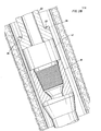
- the friction reducing apparatus of this invention indicated generally by the numbers 10 and 12 are connected into the drill pipe at preselected spaced intervals to engage wall 14 of well bore 16 and keep tool joints 18 of the drill pipe from rubbing against the low side of the well bore.
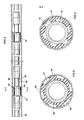
- FIGS. 2A and 2B The details of construction of the friction reducing apparatus of this invention are shown in Figures 2A and 2B. It includes tubular body 20 having central section 22 with an outside diameter smaller than the rest of the body to provide two oppositely facing shoulders 24 and 26. Mounted on--section 22 is sleeve 30 of elastomeric material constructed similarly to the stretch-on type pipe protectors that have been in use for some time.
- the sleeve In conventional stretch-on type pipe protectors, the sleeve remains stretched when placed on the drill pipe so that it will grip the pipe and be held in position by friction between the sleeve and the pipe.
- sleeve 30 it is desired for sleeve 30 to freely rotate relative to body 20, therefore, its inside diameter is designed to be slightly greater than that of the outside diameter of section 22 in its relaxed condition. It is positioned on section 22 in the same manner that conventional pipe protectors are placed on drill pipe, that is, by stretching them sufficiently to clear the tool joints on the end of the pipe after which they are placed on the body of the pipe itself but still sufficiently stretched to provide the desired friction to hold the protectors in place.
- the sleeve will be stretched sufficiently to clear upper tool joint section 32 of the body after which it is moved onto section 22 where it is then in its relaxed condition and is free to rotate relative to body 20.
- drilling fluid While drilling, drilling fluid is pumped down the drill pipe and back to the surface through annulus 34.
- the upward flow of the drilling fluid will move sleeve 30 into engagement with upper shoulder 24.
- Also tending to move the sleeve upwardly is the downward movement of the drill pipe, but this will be a relatively minor influence compared to the upward force of the drilling fluid flowing by the sleeve.
- stretch on type protectors Under certain conditions, stretch on type protectors have been forced over tool joints and up the string due to the force of the upwardly flowing drilling . fluid.
- shoulder 24 is inclined outwardly and downwardly about 30°, as shown in the drawing, to overlap the lower portion of the end of sleeve 30 to provide a force component urging the end of the sleeve inwardly toward the pipe.
- Upwardly facing shoulder 26 is provided with a plurality of slots 36 into which portions of the lower end of the sleeve can be forced to hold the sleeve against rotation during washover operations.
- the elastomeric material used to form the sleeve can be provided with hard, sharp edged particles 40, such as sand, adjacent the outer surface of the sleeve to increase the coefficient of friction between the sleeve and the open hole or casing.
- the outside surface of section 22 and opposing shoulders 24 and 26 are preferably plated with a hard, very smooth, material such as chromium.
- the drill pipe should be able to rotate relative to the sleeve with a minimum of friction thereby substantially reducing the torque required to be exerted in the drill string at the surface in order to obtain the desired torque at the bit.
- sleeve 30 is substantially shorter than .the distance between shoulders 24 and 26. This will allow the driller to pick up his pipe string a short distance to move shoulder 24 away from the upper end of sleeve 30 and get a reasonably accurate indication of what his drill string weighs. Knowing this, he can allow for the amount of weight supported by sleeves 20 while drilling and come closer to knowing what his weight indicator should read with the desired weight on the bit.
- Upper tool joint section 32 and lower tool joint section 42 are provided with a box and pin connection for :onnecting body 20 into the drill string.
- FIG. 4 An alternate embodiment of the friction reducing apparatus of this invention is shown installed in drilling string 50 at spaced intervals.
- the apparatus is indicated by the numbers 52 and 54. Both of the apparatus is the same, so only one will be described in detail.
- Apparatus 52 includes tubular body 56 that is of substantially the same design as tubular body 20 described above.
- Sleeve 58 is mounted on reduced section 60 of the body in the same manner as was sleeve 30 as described above. It is free to remain stationary while the drill pipe rotates relative to it.
- sleeve 58 which, in this embodiment, has an outside diameter equal to or slightly less than that of the well bore in which it is located. As shown in Figures 4 and 5, sleeve 58 is in engagement with the wall of the well bore. In order to allow fluid to flow by the apparatus, longitudinal grooves 62 are formed on the outer surface to allow the fluid to flow through the grooves as it moves toward the surface in annulus 66. There is a slight clearance between the inside surface of sleeve 58 and section 60 of body 56 and consequently sleeve 58 will not hold the drill string exactly in the center of the hole, but very close to it.
- FIG 6. An alternate embodiment of the apparatus of this invention is shown in Figure 6. This embodiment is designed to accomplish the same result as the embodiment shown in Figures 4 and 5. The difference here is that annular grooves 70 for the drilling fluid are located on the inside surface of sleeve 72 as opposed to the outside surface of sleeve 58.
- Body 74 is of the same design as body 56 and body 20 described above.
Landscapes
- Engineering & Computer Science (AREA)
- Life Sciences & Earth Sciences (AREA)
- Geology (AREA)
- Mining & Mineral Resources (AREA)
- Mechanical Engineering (AREA)
- Physics & Mathematics (AREA)
- Environmental & Geological Engineering (AREA)
- Fluid Mechanics (AREA)
- General Life Sciences & Earth Sciences (AREA)
- Geochemistry & Mineralogy (AREA)
- Earth Drilling (AREA)
- Processing Of Stones Or Stones Resemblance Materials (AREA)
Applications Claiming Priority (2)
| Application Number | Priority Date | Filing Date | Title |
|---|---|---|---|
| US54457983A | 1983-10-24 | 1983-10-24 | |
| US544579 | 1983-10-24 |
Publications (1)
| Publication Number | Publication Date |
|---|---|
| EP0140311A1 true EP0140311A1 (de) | 1985-05-08 |
Family
ID=24172764
Family Applications (1)
| Application Number | Title | Priority Date | Filing Date |
|---|---|---|---|
| EP84112654A Withdrawn EP0140311A1 (de) | 1983-10-24 | 1984-10-19 | Vorrichtung um die Reibung zwischen einem drehenden Bohrgestänge und dem Bohrloch zu vermindern |
Country Status (4)
| Country | Link |
|---|---|
| EP (1) | EP0140311A1 (de) |
| JP (1) | JPS60112985A (de) |
| AU (1) | AU3409784A (de) |
| NO (1) | NO844220L (de) |
Cited By (12)
| Publication number | Priority date | Publication date | Assignee | Title |
|---|---|---|---|---|
| GB2204895A (en) * | 1987-05-21 | 1988-11-23 | Stephen Francis Lloyd | Drill pipe tubing and casing protectors |
| US4832137A (en) * | 1986-05-29 | 1989-05-23 | Phillips Petroleum Company | Method for protecting a pipe casing from a drill pipe string |
| GB2211523A (en) * | 1987-10-28 | 1989-07-05 | K D Engineering Plastics Limit | Guiding drill rods |
| GB2233690A (en) * | 1989-06-29 | 1991-01-16 | Red Baron | Drill string component |
| US5009826A (en) * | 1986-05-29 | 1991-04-23 | Phillips Petroleum Company | Method of molding a composite drill collar |
| FR2690481A1 (fr) * | 1992-04-22 | 1993-10-29 | Total Sa | Dispositif de régulation de la pression dans les annulaires d'un puits pétrolier. |
| US5901798A (en) * | 1993-10-14 | 1999-05-11 | Hydril U.K. Limited | Drill pipe tubing and casing protectors |
| GB2340523A (en) * | 1998-07-30 | 2000-02-23 | Vetco Gray Inc Abb | Drill pipe protection rings |
| US8701759B1 (en) | 2013-03-14 | 2014-04-22 | Summit Energy Services, Inc. | Casing centralizer |
| CN106593313A (zh) * | 2016-12-20 | 2017-04-26 | 中国石油化工股份有限公司 | 水平井完井管柱导向减阻器 |
| USD849800S1 (en) | 2012-04-04 | 2019-05-28 | Summit Energy Services, Inc. | Casing centralizer having spiral blades |
| US10711535B2 (en) | 2013-05-29 | 2020-07-14 | Paradigm Drilling Services Limited | Downhole apparatus and method |
Citations (8)
| Publication number | Priority date | Publication date | Assignee | Title |
|---|---|---|---|---|
| US1814183A (en) * | 1929-05-20 | 1931-07-14 | Patterson Ballagh Corp | Pipe coupling and tool joint |
| US1910631A (en) * | 1929-12-30 | 1933-05-23 | Chikgan Oil Tool Company Ltd | Guide for drill pipe |
| US1985229A (en) * | 1929-12-27 | 1934-12-25 | Sullivan Machinery Co | Drilling apparatus |
| US2715552A (en) * | 1954-03-01 | 1955-08-16 | Guiberson Corp | Drill string bushing tool |
| US2813697A (en) * | 1953-06-15 | 1957-11-19 | Security Engineering Division | Stabilizer for drill collars and drill pipes |
| US3103391A (en) * | 1963-09-10 | Drill string stabilizer | ||
| US3320004A (en) * | 1964-06-19 | 1967-05-16 | Drilco Oil Tool Inc | Earth boring apparatus |
| USRE31016E (en) * | 1980-12-22 | 1982-08-24 | Conoco Inc. | Anti-friction sucker rod guide assembly |
-
1984
- 1984-10-10 AU AU34097/84A patent/AU3409784A/en not_active Abandoned
- 1984-10-19 EP EP84112654A patent/EP0140311A1/de not_active Withdrawn
- 1984-10-23 NO NO844220A patent/NO844220L/no unknown
- 1984-10-23 JP JP59221378A patent/JPS60112985A/ja active Pending
Patent Citations (8)
| Publication number | Priority date | Publication date | Assignee | Title |
|---|---|---|---|---|
| US3103391A (en) * | 1963-09-10 | Drill string stabilizer | ||
| US1814183A (en) * | 1929-05-20 | 1931-07-14 | Patterson Ballagh Corp | Pipe coupling and tool joint |
| US1985229A (en) * | 1929-12-27 | 1934-12-25 | Sullivan Machinery Co | Drilling apparatus |
| US1910631A (en) * | 1929-12-30 | 1933-05-23 | Chikgan Oil Tool Company Ltd | Guide for drill pipe |
| US2813697A (en) * | 1953-06-15 | 1957-11-19 | Security Engineering Division | Stabilizer for drill collars and drill pipes |
| US2715552A (en) * | 1954-03-01 | 1955-08-16 | Guiberson Corp | Drill string bushing tool |
| US3320004A (en) * | 1964-06-19 | 1967-05-16 | Drilco Oil Tool Inc | Earth boring apparatus |
| USRE31016E (en) * | 1980-12-22 | 1982-08-24 | Conoco Inc. | Anti-friction sucker rod guide assembly |
Cited By (17)
| Publication number | Priority date | Publication date | Assignee | Title |
|---|---|---|---|---|
| US4832137A (en) * | 1986-05-29 | 1989-05-23 | Phillips Petroleum Company | Method for protecting a pipe casing from a drill pipe string |
| US5009826A (en) * | 1986-05-29 | 1991-04-23 | Phillips Petroleum Company | Method of molding a composite drill collar |
| GB2204895A (en) * | 1987-05-21 | 1988-11-23 | Stephen Francis Lloyd | Drill pipe tubing and casing protectors |
| GB2204895B (en) * | 1987-05-21 | 1991-11-27 | Stephen Francis Lloyd | Drill pipe tubing and casing protectors |
| GB2211523A (en) * | 1987-10-28 | 1989-07-05 | K D Engineering Plastics Limit | Guiding drill rods |
| GB2233690A (en) * | 1989-06-29 | 1991-01-16 | Red Baron | Drill string component |
| GB2233690B (en) * | 1989-06-29 | 1993-02-03 | Red Baron | Drill string component |
| FR2690481A1 (fr) * | 1992-04-22 | 1993-10-29 | Total Sa | Dispositif de régulation de la pression dans les annulaires d'un puits pétrolier. |
| US5901798A (en) * | 1993-10-14 | 1999-05-11 | Hydril U.K. Limited | Drill pipe tubing and casing protectors |
| GB2340523A (en) * | 1998-07-30 | 2000-02-23 | Vetco Gray Inc Abb | Drill pipe protection rings |
| GB2340523B (en) * | 1998-07-30 | 2002-06-12 | Vetco Gray Inc Abb | Drill pipe protection rings |
| USD849800S1 (en) | 2012-04-04 | 2019-05-28 | Summit Energy Services, Inc. | Casing centralizer having spiral blades |
| USD983231S1 (en) | 2012-04-04 | 2023-04-11 | Summit Casing Services, Llc | Casing centralizer having spiral blades |
| US8701759B1 (en) | 2013-03-14 | 2014-04-22 | Summit Energy Services, Inc. | Casing centralizer |
| US9057229B2 (en) | 2013-03-14 | 2015-06-16 | Summit Energy Services, Inc. | Casing centralizer |
| US10711535B2 (en) | 2013-05-29 | 2020-07-14 | Paradigm Drilling Services Limited | Downhole apparatus and method |
| CN106593313A (zh) * | 2016-12-20 | 2017-04-26 | 中国石油化工股份有限公司 | 水平井完井管柱导向减阻器 |
Also Published As
| Publication number | Publication date |
|---|---|
| NO844220L (no) | 1985-04-25 |
| AU3409784A (en) | 1985-05-02 |
| JPS60112985A (ja) | 1985-06-19 |
Similar Documents
| Publication | Publication Date | Title |
|---|---|---|
| AU755488B2 (en) | Improvements in or relating to downhole tools | |
| US4428441A (en) | Method and apparatus for reducing the differential pressure sticking tendency of a drill string | |
| US7140432B2 (en) | Dual diameter and rotating centralizer/sub and method | |
| US8668007B2 (en) | Non-rotating casing centralizer | |
| US6209638B1 (en) | Casing accessory equipment | |
| US5082069A (en) | Combination drivepipe/casing and installation method for offshore well | |
| US2715552A (en) | Drill string bushing tool | |
| US6082457A (en) | Method of using a drill string tool | |
| CA2381212C (en) | Anti-rotation device for use with well tools | |
| AU703197B2 (en) | A Friction Reducing Tool | |
| EP0140311A1 (de) | Vorrichtung um die Reibung zwischen einem drehenden Bohrgestänge und dem Bohrloch zu vermindern | |
| US2999552A (en) | Tubular drill string member | |
| GB2362900A (en) | Friction reduction means for downhole equipment | |
| GB2261238A (en) | Turbine vibrator assembly | |
| US7156171B2 (en) | Dual diameter and rotating centralizer/sub | |
| US5033558A (en) | Well tool for use with down-hole drilling apparatus | |
| GB2565432B (en) | Stop collar | |
| US3762472A (en) | Casing stand-off band for use during the running and cementing of casing in wellbores | |
| US4043410A (en) | Anti-sticking tool for drill pipe | |
| Moore et al. | Reduction of drill string torque and casing wear in extended reach wells using non-rotating drill pipe protectors | |
| US4919208A (en) | Method and apparatus for manipulating tubing in a well | |
| RU2183250C2 (ru) | Стабилизатор |
Legal Events
| Date | Code | Title | Description |
|---|---|---|---|
| PUAI | Public reference made under article 153(3) epc to a published international application that has entered the european phase |
Free format text: ORIGINAL CODE: 0009012 |
|
| AK | Designated contracting states |
Designated state(s): AT BE CH DE FR GB IT LI LU NL SE |
|
| STAA | Information on the status of an ep patent application or granted ep patent |
Free format text: STATUS: THE APPLICATION IS DEEMED TO BE WITHDRAWN |
|
| 18D | Application deemed to be withdrawn |
Effective date: 19860108 |
|
| RIN1 | Information on inventor provided before grant (corrected) |
Inventor name: ANDERS, EDWARD O. |