EP0140212B1 - A fastening means for mounting a plate originally made of several small pieces of plate onto a substantially planar wall - Google Patents
A fastening means for mounting a plate originally made of several small pieces of plate onto a substantially planar wall Download PDFInfo
- Publication number
- EP0140212B1 EP0140212B1 EP84111966A EP84111966A EP0140212B1 EP 0140212 B1 EP0140212 B1 EP 0140212B1 EP 84111966 A EP84111966 A EP 84111966A EP 84111966 A EP84111966 A EP 84111966A EP 0140212 B1 EP0140212 B1 EP 0140212B1
- Authority
- EP
- European Patent Office
- Prior art keywords
- bottom member
- intermediary
- plate
- intermediary member
- engaging means
- Prior art date
- Legal status (The legal status is an assumption and is not a legal conclusion. Google has not performed a legal analysis and makes no representation as to the accuracy of the status listed.)
- Expired
Links
Images


Classifications
-
- E—FIXED CONSTRUCTIONS
- E04—BUILDING
- E04F—FINISHING WORK ON BUILDINGS, e.g. STAIRS, FLOORS
- E04F13/00—Coverings or linings, e.g. for walls or ceilings
- E04F13/07—Coverings or linings, e.g. for walls or ceilings composed of covering or lining elements; Sub-structures therefor; Fastening means therefor
- E04F13/08—Coverings or linings, e.g. for walls or ceilings composed of covering or lining elements; Sub-structures therefor; Fastening means therefor composed of a plurality of similar covering or lining elements
- E04F13/0801—Separate fastening elements
- E04F13/0832—Separate fastening elements without load-supporting elongated furring elements between wall and covering elements
- E04F13/0833—Separate fastening elements without load-supporting elongated furring elements between wall and covering elements not adjustable
- E04F13/0839—Separate fastening elements without load-supporting elongated furring elements between wall and covering elements not adjustable the fastening elements situated at the corners of the covering elements, not extending through the covering
-
- A—HUMAN NECESSITIES
- A47—FURNITURE; DOMESTIC ARTICLES OR APPLIANCES; COFFEE MILLS; SPICE MILLS; SUCTION CLEANERS IN GENERAL
- A47G—HOUSEHOLD OR TABLE EQUIPMENT
- A47G1/00—Mirrors; Picture frames or the like, e.g. provided with heating, lighting or ventilating means
- A47G1/16—Devices for hanging or supporting pictures, mirrors, or the like
- A47G1/20—Picture hooks; X-hooks
- A47G1/21—Picture hooks; X-hooks with clamping action
- A47G1/215—Mirror clamps
Definitions
- the invention relates to a fastening member for mounting a plate optionally made of several small pieces of plate onto a substantially planar wall, said plate for instance being a mirror made of several small pieces of mirror or a relief made of several small pieces of relief, comprising a bottom member to be secured on the wall, an intermediary member secured on top of said bottom member and including a surface for carrying and/or supporting that plate, optionally the pieces of plate, and a cover situated on top of said intermediate member and serving to secure the plate, optionally the pieces of plate to the intermediary member.
- a fastening member of this type is known from FR-A-1 472 193.
- the wall onto which the mirror is mounted must be completely planar.
- these walls are not always planar because of unevennesses in the layer of plaster, or in case of walls of wood said unevennesses are caused by deformations on account of moisture or displacement of the boards.
- the above problem may also arise when mounting a large plate of several smaller pieces of plate with a light-reflecting or gleaming surface such as for instance an enamelled surface.
- a light-reflecting or gleaming surface such as for instance an enamelled surface.
- the object of the invention is to provide a fastening means of the above type and allowing an easy mounting of the plate onto a not completely planar wall without involving the risk of said plate presenting a skew surface, and which furthermore implies that a plate made of several smaller pieces of plate forms a completely planar front surface without skew pieces of plate upon the mounting.
- a fastening member of the type as described at the beginning of this specification is characterised in that said bottom member has first engaging means with surface portions located in different distances from the bottom surface of said bottom member, that said intermediary member has second engaging means with surface portions located in different distances from the top surface of said intermediary member, that said first and second engaging means engage each other, that said intermediary member is rotatably mounted on said bottom member so that different surface portions of said first and second engaging means engage each other for adjusting the distance of its top surface from the bottom surface of the bottom member, and that said surface comprises projections for carrying and/or supporting corners of the plate, optionally of said pieces of plate.
- the four fastening means used for mounting the plate ensure that the top surface of the intermediary member of said fastening means is adjusted so as to be at a predetermined level in such a manner that the plate is only carried and/or supported by the fastening means.
- the plate is not allowed to touch possible lopsidenesses on the wall.
- a plate mounted in this manner is not presenting a skew surface when it is being mounted.
- the bottom member may for instance be secured to the wall by means of pins.
- the bottom member and intermediary member of a fastening means are initially mounted at each of the locations corresponding to the corner points of the plate mounted. Subsequently said intermediary members are adjusted in such a manner that their top surfaces are at one and the same level suitably spaced from the uneven wall. Finally the individual pieces of plate are mounted on the projections and the pieces of plate are fixedly pressed against the intermediary members by means of the covers.
- the fastening means turned out to be particularly suited for mounting mirrors composed of smaller pieces of mirror, e.g. four such pieces of mirror. In the latter case nine fastening means are necessary.
- the front surface of the completed mirror is nice uniform without the tendency of incorrect light-reflections and incorrect reflections of the person looking at himself in the mirror.
- the adjustment of the distance between the top surface of the intermediary member and the bottom surface of the bottom member may be carried out in short steps. Such a procedure turned out in practice to allow a satisfactory mounting of the pieces of plate without each fastening means being too complicated.
- the bottom side of the intermediary member may be provided with a recess receiving at least part of the bottom member.
- The-intermediary member may according to the invention - compared to the bottom member - be adjustable into a plurality of angular positions, preferably four, with a mutual distance of 90°, 'whereby it is easy to adjust each fastening means during the mounting procedure.
- the surface portions of said first engaging means are arranged along sides of the bottom member and the surface portions of said second engaging means are arranged along sides of the intermediary member while the surface portions of each of said first and second engaging means are formed by step surfaces.
- all the step surfaces on the engaging means of the bottom member may abut all the step surfaces of each of the engaging means of the intermediary member when said intermediary member is in a specific angular position, whereas only a minority of said step surfaces on each engaging means of the bottom member abut the corresponding step surfaces of each engaging means of the intermediary member in the remaining angular positions of said intermediary member, the distance of the top surface of the intermediary member to the bottom surface of the bottom member changing in said remaining angular positions.
- This embodiment of the fastening means is particularly suited for mounting compound mirrors.
- each engaging means may according to the invention comprise four step surfaces, viz. in a first low level, a second slightly higher level, a third still higher level, and a fourth highest level, and considerable changes in distances may exist between two neighboring step surfaces, whereby it is obtained in a simple manner that the top surface of the intermediary member is at various levels in the various angular positions of said intermediary member.
- a further embodiment of the fastening means according to the invention is characterised in that the engaging means at the first side of the bottom member comprises step surfaces arranged in the following level sequence: First, second, third, and fourth level; that the engaging means at the second side of the bottom member comprises step surfaces arranged in the following level sequence: Fourth, first, second, and third level; that the engaging means at the third side of the bottom member comprises step surfaces arranged in the following level sequence: Third, fourth, first, and second level; and that the engaging means at the fourth side of the bottom member comprises step surfaces arranged in the following level sequence: Second, third, fourth, and first level, whereby the step surfaces of the opposing engaging means on the intermediary member comprise levels complementary to the step surface levels on the bottom member. In this manner a great constructional simplicity is obtained.
- the first low level of the step surfaces may be fictive as it corresponds to the level of the bottom surface of the bottom member and is situated at an opening in the bottom member, whereby material is saved in connection with the bottom member.
- the top side of the bottom member may comprise guide pins in each corner, said pins being adapted to cooperate with corresponding guide openings on the bottom side of the intermediary member.
- the intermediary member catches the bottom member when a user is to mount the fastening means onto the wall, and furthermore the intermediary member is prevented from turning relative to the bottom member when the latter is at the highest level.
- the projections of the intermediary member may be provided on projections on the top surface of the intermediary member, whereby said projections are provided in a very simple manner.
- the cover may be secured to the intermediary member by means of securing pins projecting from the cover and cooperating with auxiliary openings in the projections of the intermediary member, whereby the cover can be secured very reliably to the intermediary member in such a manner that the piece of plate such as for instance the piece of mirror is well retained against the intermediary member.
- the securing pins may be free of grooves, and the auxiliary openings of the intermediary member may comprise recesses all being located to the same side and therefore influencing the securing pins on various sides depending on the angular position of the cover.
- This embodiment is particularly suited in connection with a demounting and a new mounting procedure.
- the intermediary member is according to the invention secured to the bottom member by means of a central fixing means such as a screw with associated wall plug extending both through the intermediary member and the bottom member and into the wall.
- a central fixing means such as a screw with associated wall plug extending both through the intermediary member and the bottom member and into the wall.
- the bottom member and the intermediary member may be made of a harder material, preferably acetal, than the cover preferably made of polyamide or propene (polypropylene).
- the cover preferably made of polyamide or propene (polypropylene).
- the bottom member may be secured to the wall by means of pin-like members extending through the channel in the guide pins of the bottom member.
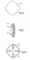
- the fastening means comprises a bottom member 1, an intermediary member 15, and a cover 30, said parts engaging each other when the fastening means is mounted on a wall 40.
- Figure 18 illustrates a mirror 45 composed of four pieces of mirror 41, 42, 43, 44. The mirror is secured to an uneven wall by means of nine fastening means according to the invention.
- the top surface of the intermediary member of each fastening means is adjustable and serves to support each piece of mirror it is ensured that none of the pieces of mirror is positioned out of plane relative to the remaining three pieces of mirror.
- Figures 1, 2, and 19 illustrate the bottom member, and Figure 2 illustrates how said bottom member comprises a top side 2 and a bottom surface 4.
- Figures 3, 4, and 5 illustrate the intermediary member comprising a top surface 17 and a bottom surface 16.
- the surface 16 faces downwards towards the top side 2 of the bottom surface.
- the distance h, cf. Figure 9 between the top surface 17 of the intermediary member and the bottom surface 4 of the bottom member is adjustable, which implies that the surface 17 may be positioned relatively close to the wall or relatively far from the wall.
- FIG 3 is provided with projections 25a, 25b, 25c, 25d - not all the projections have been provided with reference numerals - and these projections serve to support and/or carry the corners of the pieces of plate 41, 42, 43, 44 which are to be mounted.
- a single corner piece 46 has been indicated by a dotted line.
- the cover 30 is illustrated in greater details in Figures 6, 7, and 8. This cover is provided with a plurality of securing pins 31, 32, 33, not all the securing pins being provided with reference numerals. These securing pins can be pressed into some auxiliary openings 18, 19 - only a few openings being provided with reference numerals - in some projections 21, not all the projections being provided with reference numerals. The latter projections are provided with the above projections 25a, 25b, 25c, 25d.
- the bottom side 16 of the intermediary member is provided with a recess 28 receiving a portion 11 of the bottom member 1.
- Some guide pins 8, cf. below, on the bottom member ensure that the intermediary member can be turned when it is positioned at the highest level relative to the bottom member.
- Figure 3 illustrates how the intermediary member can be turned - indicated by the double arrows A and B.
- the intermediary member can be turned into four angular positions which on a dial correspond to 9 and 12 o'clock a.m. and 3 and 6 o'clock p.m., respectively.
- the bottom member 1 comprises at each side 1', 1", 1"', 1"" engaging means 1a, 1b, 1c, and 1d.
- Each engaging means comprises a plurality of step surfaces, viz. in the present case four such surfaces.
- the engaging means 1a comprises the step surfaces 1aa, 1ab, 1ac, and 1ad.
- the engaging means 1b comprises the step surfaces 1 ba, 1 bb, 1 bc, 1 bd.
- the engaging means 1c comprises the step surfaces 1ca, 1cb, 1cc, and 1cd, whereas the engaging means Id comprises the step surfaces 1da, 1db, 1dc, and 1dd.
- the engaging means 15a, 15b, 15c, and 15d are provided at the sides 15', 15", 15" ', 15" " of the intermediary member.
- the engaging means 15a comprises the step surfaces 15aa, 15ab, 15ac, 15ad.
- the engaging means 15b comprises the step surface 15ba, 15bb, 15bc, 15bd.
- the engaging means 15c comprises the step surfaces 15ca, 15cb, 15cc, 15cd, whereas the engaging means 15d comprises the step surfaces 15da, 15db, 15dc, 15dd.
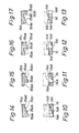
- Figures 10 to 13 are longitudinal sectional views through each of the engaging means 1 a, 1 b, 1 c, and 1 d of the bottom member, whereas Figures 14 to 17 arelongitudinal sectional views through the engaging means 15a, 15b, 15c, and 15d of the intermediary member.
- the engaging means 1a and 15a are complementary, and the same applies to the engaging means 1 and 15b, etc.
- the engaging means 15a abuts the engaging means 1a
- the engaging means 15b abuts the engaging means 1 b, etc. which is the case in one of the four angular positions of the intermediary member, all four step surfaces of two opposing engaging means abut each other.
- the contact surface common to two engaging means corresponds only to a single step surface.
- the top surface of the intermediary member and the bottom surface of the bottom member are interspaced as much as possible.
- each engaging means are positioned at various levels, viz. at a first low level, a second slightly higher level, a third still higher level, and a fourth highest level. As illustrated considerable distances may exist between two neighboring surfaces, e.g. 15dc and 15dd.
- Figure 10 illustrates how the first engaging means on the bottom member comprises the step surfaces 1aa, 1ab, 1ac, 1ad positioned in the following level sequence: First, second, third, and fourth level.
- the second engaging means on the bottom member comprises the step surfaces 1 ba, 1 bb, 1bc, 1bd positioned in the following level sequence: Fourth, first, second, and third level.
- the third engaging means 1c on the bottom member comprises its step surfaces 1ca, 1cb, 1cc, 1cd positioned in the following level sequence: Third, fourth, first, and second level.
- the fourth engaging means 1d on the bottom member comprises its step surfaces 1da, 1db, 1dc, 1dd positioned in the following level sequence: Second, third, fourth, and first level.
- the step surfaces of the opposing engaging means 15a, 15b, 15c, 15d on the intermediary member 15 comprise levels complementary to the step surface levels on the bottom member 1.
- the first low level, cf. 1aa of Figure 10 may be fictive, as it is in fact a question of an opening in the bottom member.
- the low level corresponds to the bottom surface of the bottom member.
- the dotted.line in Figure 2 indicates a layer 6 of material, which can be removed so as to produce openings in the bottom member 2, cf. Figure 19, whereby the openings appear clearly at 7. In this manner material is saved in connection with the bottom member.
- the bottom member 1 comprises in each corner guide pins 8 adapted to cooperate with corresponding guide openings 23 in the bottom side of the intermediary member 15. These guide pins prevent a turning of the intermediary member when the latter is positioned at the uppermost level.
- the auxiliary openings 18, 19 of the intermediary member 15 may comprise small recesses 18a, 19a, 20a, not all the recesses being provided with reference numerals. All these recesses are situated to the same side and consequently influence the securing pins 31, 32,33 of the cover on various sides depending on the angular position of the cover.
- bottom member 1 is secured to the wall 40 by means of pin-like members 9 such as thin pins or nails, cf. Figures 1 and 19. These pins or nails may extend through the channel 10 in the guide pins 8.
- pin-like members 9 such as thin pins or nails, cf. Figures 1 and 19. These pins or nails may extend through the channel 10 in the guide pins 8.
- the bottom member is positioned on the wall exactly in the way shown in Figure 1. The latter has been symbolically indicated by means of the two fat arrows in the middle of Figure 1.
- the intermediary member 15 is usually secured to the bottom member 1 by means of a central fixing member 47 such as a screw with associated wall plug extending both through the intermediary member and the bottom member and into the wall 40.
- a central fixing member 47 such as a screw with associated wall plug extending both through the intermediary member and the bottom member and into the wall 40.
- the step surfaces of the engaging means may optionally be slightly curved.
Landscapes
- Engineering & Computer Science (AREA)
- Architecture (AREA)
- Civil Engineering (AREA)
- Structural Engineering (AREA)
- Road Signs Or Road Markings (AREA)
- Finishing Walls (AREA)
- Connection Of Plates (AREA)
- Mirrors, Picture Frames, Photograph Stands, And Related Fastening Devices (AREA)
- Purses, Travelling Bags, Baskets, Or Suitcases (AREA)
Priority Applications (1)
| Application Number | Priority Date | Filing Date | Title |
|---|---|---|---|
| AT84111966T ATE39832T1 (de) | 1983-10-07 | 1984-10-05 | Vorrichtung zum aufhaengen von aus mehreren kleinen teilen hergestellten platten auf eine im wesentlichen ebene wand. |
Applications Claiming Priority (2)
| Application Number | Priority Date | Filing Date | Title |
|---|---|---|---|
| DK4627/83 | 1983-10-07 | ||
| DK462783A DK149581C (da) | 1983-10-07 | 1983-10-07 | Holder til brug ved opsaetning af en eventuelt af flere mindre pladestykker bestaaende plade paa en i hovedsagen plan vaeg |
Publications (3)
| Publication Number | Publication Date |
|---|---|
| EP0140212A2 EP0140212A2 (en) | 1985-05-08 |
| EP0140212A3 EP0140212A3 (en) | 1986-01-22 |
| EP0140212B1 true EP0140212B1 (en) | 1989-01-11 |
Family
ID=8135255
Family Applications (1)
| Application Number | Title | Priority Date | Filing Date |
|---|---|---|---|
| EP84111966A Expired EP0140212B1 (en) | 1983-10-07 | 1984-10-05 | A fastening means for mounting a plate originally made of several small pieces of plate onto a substantially planar wall |
Country Status (4)
| Country | Link |
|---|---|
| EP (1) | EP0140212B1 (da) |
| AT (1) | ATE39832T1 (da) |
| DE (1) | DE3476019D1 (da) |
| DK (1) | DK149581C (da) |
Families Citing this family (3)
| Publication number | Priority date | Publication date | Assignee | Title |
|---|---|---|---|---|
| US4599768A (en) * | 1985-05-13 | 1986-07-15 | Illinois Tool Works Inc. | Spin welded fastening assembly |
| DE10037683C2 (de) * | 2000-07-31 | 2002-11-07 | Dorma Gmbh & Co Kg | Befestigungsvorrichtung für flächenartige Elemente |
| IT1394963B1 (it) * | 2009-07-28 | 2012-07-27 | Ind I A S P A | Pinza modulare per la composizione di strutture tecniche di arredo, protezione e/o delimitazione |
Family Cites Families (3)
| Publication number | Priority date | Publication date | Assignee | Title |
|---|---|---|---|---|
| FR794461A (fr) * | 1935-08-30 | 1936-02-18 | Dispositifs de fixation de tous objets, rendant la vis ou la pointe invisible | |
| FR1472193A (fr) * | 1966-01-21 | 1967-03-10 | Perfectionnements aux supports pour la fixation des glaces, miroirs ou analogues | |
| JPS587851B2 (ja) * | 1977-02-05 | 1983-02-12 | 株式会社ニフコ | 留め具 |
-
1983
- 1983-10-07 DK DK462783A patent/DK149581C/da active
-
1984
- 1984-10-05 EP EP84111966A patent/EP0140212B1/en not_active Expired
- 1984-10-05 DE DE8484111966T patent/DE3476019D1/de not_active Expired
- 1984-10-05 AT AT84111966T patent/ATE39832T1/de not_active IP Right Cessation
Also Published As
| Publication number | Publication date |
|---|---|
| EP0140212A3 (en) | 1986-01-22 |
| DK149581B (da) | 1986-08-04 |
| EP0140212A2 (en) | 1985-05-08 |
| ATE39832T1 (de) | 1989-01-15 |
| DK462783D0 (da) | 1983-10-07 |
| DK462783A (da) | 1985-04-08 |
| DK149581C (da) | 1987-05-18 |
| DE3476019D1 (en) | 1989-02-16 |
Similar Documents
| Publication | Publication Date | Title |
|---|---|---|
| USD310027S (en) | Beverage tray | |
| USD311098S (en) | Chair | |
| USD311848S (en) | Automatic bread maker | |
| USD246911S (en) | Automatic blind suturing machine | |
| USD270130S (en) | Taco serving tray | |
| USD338814S (en) | Hand-held tool for gauging clapboard and shingles | |
| USD279943S (en) | Chair | |
| EP0140212B1 (en) | A fastening means for mounting a plate originally made of several small pieces of plate onto a substantially planar wall | |
| USD297287S (en) | Jump seat | |
| USD249726S (en) | Playing piece for game | |
| US5301912A (en) | Adjustable and movable hook structure | |
| USD284513S (en) | Extension ladder shelf | |
| USD291896S (en) | Coin operated coffee brewer | |
| USD289912S (en) | Golf putter head | |
| USD282798S (en) | Table base | |
| USD289216S (en) | Automatic teller machine | |
| USD307824S (en) | Auto snack tray | |
| USD299293S (en) | Chair frame | |
| USD314966S (en) | Control unit for a combined car radio receiver cassett player and digital clock | |
| USD306335S (en) | Snap-on level for golf putters | |
| USD249724S (en) | Playing piece for game | |
| USD337279S (en) | Combination level and template | |
| USD285874S (en) | Chair | |
| USD285859S (en) | Coin tray | |
| USD331781S (en) | Coin discriminator for an automatic vending machine |
Legal Events
| Date | Code | Title | Description |
|---|---|---|---|
| PUAI | Public reference made under article 153(3) epc to a published international application that has entered the european phase |
Free format text: ORIGINAL CODE: 0009012 |
|
| AK | Designated contracting states |
Designated state(s): AT BE CH DE FR GB LI NL SE |
|
| PUAL | Search report despatched |
Free format text: ORIGINAL CODE: 0009013 |
|
| AK | Designated contracting states |
Designated state(s): AT BE CH DE FR GB LI NL SE |
|
| 17P | Request for examination filed |
Effective date: 19860616 |
|
| 17Q | First examination report despatched |
Effective date: 19870701 |
|
| GRAA | (expected) grant |
Free format text: ORIGINAL CODE: 0009210 |
|
| AK | Designated contracting states |
Kind code of ref document: B1 Designated state(s): AT BE CH DE FR GB LI NL SE |
|
| REF | Corresponds to: |
Ref document number: 39832 Country of ref document: AT Date of ref document: 19890115 Kind code of ref document: T |
|
| REF | Corresponds to: |
Ref document number: 3476019 Country of ref document: DE Date of ref document: 19890216 |
|
| ET | Fr: translation filed | ||
| PLBE | No opposition filed within time limit |
Free format text: ORIGINAL CODE: 0009261 |
|
| STAA | Information on the status of an ep patent application or granted ep patent |
Free format text: STATUS: NO OPPOSITION FILED WITHIN TIME LIMIT |
|
| 26N | No opposition filed | ||
| EAL | Se: european patent in force in sweden |
Ref document number: 84111966.2 |
|
| REG | Reference to a national code |
Ref country code: CH Ref legal event code: PUE Owner name: IKEA INTERNATIONAL A/S |
|
| REG | Reference to a national code |
Ref country code: GB Ref legal event code: 732E |
|
| REG | Reference to a national code |
Ref country code: FR Ref legal event code: TP |
|
| NLS | Nl: assignments of ep-patents |
Owner name: IKEA INTERNATIONAL A/S |
|
| PGFP | Annual fee paid to national office [announced via postgrant information from national office to epo] |
Ref country code: SE Payment date: 19971024 Year of fee payment: 14 |
|
| PGFP | Annual fee paid to national office [announced via postgrant information from national office to epo] |
Ref country code: AT Payment date: 19971028 Year of fee payment: 14 |
|
| PGFP | Annual fee paid to national office [announced via postgrant information from national office to epo] |
Ref country code: NL Payment date: 19971031 Year of fee payment: 14 |
|
| PGFP | Annual fee paid to national office [announced via postgrant information from national office to epo] |
Ref country code: CH Payment date: 19971103 Year of fee payment: 14 |
|
| PGFP | Annual fee paid to national office [announced via postgrant information from national office to epo] |
Ref country code: DE Payment date: 19971114 Year of fee payment: 14 |
|
| PGFP | Annual fee paid to national office [announced via postgrant information from national office to epo] |
Ref country code: BE Payment date: 19971211 Year of fee payment: 14 |
|
| PG25 | Lapsed in a contracting state [announced via postgrant information from national office to epo] |
Ref country code: AT Free format text: LAPSE BECAUSE OF NON-PAYMENT OF DUE FEES Effective date: 19981005 |
|
| PG25 | Lapsed in a contracting state [announced via postgrant information from national office to epo] |
Ref country code: SE Free format text: LAPSE BECAUSE OF NON-PAYMENT OF DUE FEES Effective date: 19981006 |
|
| PGFP | Annual fee paid to national office [announced via postgrant information from national office to epo] |
Ref country code: GB Payment date: 19981009 Year of fee payment: 15 |
|
| PGFP | Annual fee paid to national office [announced via postgrant information from national office to epo] |
Ref country code: FR Payment date: 19981014 Year of fee payment: 15 |
|
| PG25 | Lapsed in a contracting state [announced via postgrant information from national office to epo] |
Ref country code: LI Free format text: LAPSE BECAUSE OF NON-PAYMENT OF DUE FEES Effective date: 19981031 Ref country code: CH Free format text: LAPSE BECAUSE OF NON-PAYMENT OF DUE FEES Effective date: 19981031 Ref country code: BE Free format text: LAPSE BECAUSE OF NON-PAYMENT OF DUE FEES Effective date: 19981031 |
|
| BERE | Be: lapsed |
Owner name: IKEA INTERNATIONAL A/S Effective date: 19981031 |
|
| PG25 | Lapsed in a contracting state [announced via postgrant information from national office to epo] |
Ref country code: NL Free format text: LAPSE BECAUSE OF NON-PAYMENT OF DUE FEES Effective date: 19990501 |
|
| REG | Reference to a national code |
Ref country code: CH Ref legal event code: PL |
|
| EUG | Se: european patent has lapsed |
Ref document number: 84111966.2 |
|
| PG25 | Lapsed in a contracting state [announced via postgrant information from national office to epo] |
Ref country code: FR Free format text: LAPSE BECAUSE OF NON-PAYMENT OF DUE FEES Effective date: 19990630 |
|
| NLV4 | Nl: lapsed or anulled due to non-payment of the annual fee |
Effective date: 19990501 |
|
| REG | Reference to a national code |
Ref country code: FR Ref legal event code: ST |
|
| PG25 | Lapsed in a contracting state [announced via postgrant information from national office to epo] |
Ref country code: DE Free format text: LAPSE BECAUSE OF NON-PAYMENT OF DUE FEES Effective date: 19990803 |
|
| PG25 | Lapsed in a contracting state [announced via postgrant information from national office to epo] |
Ref country code: GB Free format text: LAPSE BECAUSE OF NON-PAYMENT OF DUE FEES Effective date: 19991005 |
|
| GBPC | Gb: european patent ceased through non-payment of renewal fee |
Effective date: 19991005 |