EP0139507B1 - Island record films; fabrication - Google Patents
Island record films; fabrication Download PDFInfo
- Publication number
- EP0139507B1 EP0139507B1 EP84306861A EP84306861A EP0139507B1 EP 0139507 B1 EP0139507 B1 EP 0139507B1 EP 84306861 A EP84306861 A EP 84306861A EP 84306861 A EP84306861 A EP 84306861A EP 0139507 B1 EP0139507 B1 EP 0139507B1
- Authority
- EP
- European Patent Office
- Prior art keywords
- layer
- islands
- absorber
- storage medium
- island
- Prior art date
- Legal status (The legal status is an assumption and is not a legal conclusion. Google has not performed a legal analysis and makes no representation as to the accuracy of the status listed.)
- Expired
Links
Images


Classifications
-
- G—PHYSICS
- G11—INFORMATION STORAGE
- G11B—INFORMATION STORAGE BASED ON RELATIVE MOVEMENT BETWEEN RECORD CARRIER AND TRANSDUCER
- G11B7/00—Recording or reproducing by optical means, e.g. recording using a thermal beam of optical radiation by modifying optical properties or the physical structure, reproducing using an optical beam at lower power by sensing optical properties; Record carriers therefor
- G11B7/24—Record carriers characterised by shape, structure or physical properties, or by the selection of the material
- G11B7/241—Record carriers characterised by shape, structure or physical properties, or by the selection of the material characterised by the selection of the material
-
- G—PHYSICS
- G11—INFORMATION STORAGE
- G11B—INFORMATION STORAGE BASED ON RELATIVE MOVEMENT BETWEEN RECORD CARRIER AND TRANSDUCER
- G11B7/00—Recording or reproducing by optical means, e.g. recording using a thermal beam of optical radiation by modifying optical properties or the physical structure, reproducing using an optical beam at lower power by sensing optical properties; Record carriers therefor
- G11B7/24—Record carriers characterised by shape, structure or physical properties, or by the selection of the material
- G11B7/241—Record carriers characterised by shape, structure or physical properties, or by the selection of the material characterised by the selection of the material
- G11B7/242—Record carriers characterised by shape, structure or physical properties, or by the selection of the material characterised by the selection of the material of recording layers
- G11B7/243—Record carriers characterised by shape, structure or physical properties, or by the selection of the material characterised by the selection of the material of recording layers comprising inorganic materials only, e.g. ablative layers
- G11B2007/24302—Metals or metalloids
- G11B2007/24308—Metals or metalloids transition metal elements of group 11 (Cu, Ag, Au)
-
- G—PHYSICS
- G11—INFORMATION STORAGE
- G11B—INFORMATION STORAGE BASED ON RELATIVE MOVEMENT BETWEEN RECORD CARRIER AND TRANSDUCER
- G11B7/00—Recording or reproducing by optical means, e.g. recording using a thermal beam of optical radiation by modifying optical properties or the physical structure, reproducing using an optical beam at lower power by sensing optical properties; Record carriers therefor
- G11B7/24—Record carriers characterised by shape, structure or physical properties, or by the selection of the material
- G11B7/241—Record carriers characterised by shape, structure or physical properties, or by the selection of the material characterised by the selection of the material
- G11B7/242—Record carriers characterised by shape, structure or physical properties, or by the selection of the material characterised by the selection of the material of recording layers
- G11B7/243—Record carriers characterised by shape, structure or physical properties, or by the selection of the material characterised by the selection of the material of recording layers comprising inorganic materials only, e.g. ablative layers
- G11B2007/24302—Metals or metalloids
- G11B2007/24316—Metals or metalloids group 16 elements (i.e. chalcogenides, Se, Te)
-
- G—PHYSICS
- G11—INFORMATION STORAGE
- G11B—INFORMATION STORAGE BASED ON RELATIVE MOVEMENT BETWEEN RECORD CARRIER AND TRANSDUCER
- G11B7/00—Recording or reproducing by optical means, e.g. recording using a thermal beam of optical radiation by modifying optical properties or the physical structure, reproducing using an optical beam at lower power by sensing optical properties; Record carriers therefor
- G11B7/24—Record carriers characterised by shape, structure or physical properties, or by the selection of the material
- G11B7/241—Record carriers characterised by shape, structure or physical properties, or by the selection of the material characterised by the selection of the material
- G11B7/252—Record carriers characterised by shape, structure or physical properties, or by the selection of the material characterised by the selection of the material of layers other than recording layers
- G11B7/258—Record carriers characterised by shape, structure or physical properties, or by the selection of the material characterised by the selection of the material of layers other than recording layers of reflective layers
- G11B7/2585—Record carriers characterised by shape, structure or physical properties, or by the selection of the material characterised by the selection of the material of layers other than recording layers of reflective layers based on aluminium
Definitions
- the present invention relates to an optical storage medium comprising a film of metal rendered in semicontinuous, "island” form.
- Such "insular" films may be laid down (e.g., vacuum deposited) so as to exhibit a fairly uniform pattern of islands and void-intervals, with fairly uniform island size and thickness-doing so with techniques that are (rather precisely) controllable and repeatable, and are relatively straightforward and inexpensive (e.g., using a known type of vacuum deposition).
- the recording medium comprises a substrate, a first stabilising layer, a metallic recording layer, and a second stabilising layer.
- the first stabilising layer is composed of an auxiliary metal oxide layer and an inorganic compound layer.
- EP-A-83396 discloses a film consisting of a substrate, a reflective layer supported on the substrate, a transparent spacer layer, an absorber layer having islands of gold, and a dust cover.
- the present invention relates to an optical storage medium comprising a mechanically supportive substrate, a reflective layer supported on the substrate, a transparent spacer layer on the reflective layer, an absorber layer on the spacer layer, the thickness of said spacer layer being selected to co-operate with said absorber layer to provide a dark-mirror effect at a predetermined light wavelength and said absorber layer being a gold island layer.
- the invention is characterised by a polymer overcoat on said absorber layer providing . fissures adjacent to said absorber layer permitting migration of said gold islands in said absorber layer.
- trilayer optical data storage media utilize a rigid substrate upon which is deposited, in order, an opaque metallic reflector layer, a dielectric spacer, and a thin absorber (or information layer, typically comprised of a low-melting-point metal).
- the thickness of the dielectric spacer is chosen such that the information layer is at the peak of the standing wave of the optical electric field upon exposure to a focused beam of laser radiation.
- the incident radiation is absorbed in a write-site of the information layer, the temperature of this site rises until a physical "disruption" or deformation of the information layer occurs. This disruption, of "deformation” at the write-site, exposes the underlying reflector, resulting in a large and irreversible increase of reflectance, and so creating a written "bit".
- bit-forming processes may be understood, respectively, as “ablation”, “rim formation”, and “bubble formation”-all being disruptive and/or deformational. That is, those bit-formation mechanisms involve some significant “deformation” and/or “disruption”, i.e., either a volume change of significant proportions, or mass transport of debris over distances that are large with respect to the radius of the bit site. As a consequence, all these mechanisms are viewed as inherently incompatible with the usual presence of massive conventional in-contact overcoat. This have gi ' . ' .en rise to some complex overcoat configurations designed to accommodate these gross physical movements involved in such bit formation; e.g., air gaps" and other "non-contact” design approaches.
- island films are made and used, and includes details of this "agglomeration" mechanism in trilayer media incorporating island-gold as the information layer.
- a phenomenological model is presented to explain observed behavior, describing "agglomeration” and how it functions in the presence of an in-contact overcoat.
- Record 10 will be understood as comprising a support 12 on which an "anti-reflective base 1-AR is laid (like AR in Fig. 1), comprising a dielectric spacer 14 on an opaque metallic reflective layer 13, with absorber film 15 placed atop spacer 14.
- absorber 15 comprises a very thin (minimum mass) film of "gold material” laid down in an “island layer” configuration and intended to function as an absorber film (cf., the Te film in the "Te Example”; e.g., apt for somewhat similar recording methods and with similar means).
- absorber film cf., the Te film in the "Te Example”; e.g., apt for somewhat similar recording methods and with similar means.
- film 15 be laid down to be semi-continuous (discontinuous), being formed in a highly-uniform "island" configuration (e.g., roughly exemplified in Fig. 11, a 100,OOOxTEM. or Transmission Electromicrograph, and as further described below).
- the underlying spacer layer 14, reflector layer 13 and substrate 12 are (at least functionally) otherwise the same as in “Te Example", and thus will be understood as functioning as a "trilayer” (with absorber 15) as understood in the art.
- "Gold-island” absorber film 15 may be formed by vapor-depositing gold onto the surface of dielectric spacer 4 until (monitoring the well-known "trilayer” effect) surface-reflectivity of 15 first drops to preselected value R m (10% reflectance, here), taking care to render the required "insular” (islands) configuration.
- Reflectance R m may, conveniently, be set at any desired value consistent with adequate "writing” and readout.
- an R of about 10% is arbitrarily selected (minimum for proper focusing, etc.
- Absorber layer 15 thus comprises an extremely thin, highly uniform, minimum-mass, "island- deposit” of gold which is vapor-deposited (thermally evaporated or sputtered) onto spacer layer 14 (i.e., on a relatively flat; e.g., 0.5 A record- surface thereof).
- spacer layer 14 i.e., on a relatively flat; e.g., 0.5 A record- surface thereof.
- pure gold may be so deposited in large vacuum chamber 0.133 10 -3 ⁇ 0.133 ⁇ 10-4 Pa (10 -6 ⁇ 10 -7 Torr.), from a molybdenum boat which is resistance-heated-deposition rate being about 0.5-1.0 nm/sec.). All substrates are cleaned according to present good practice for optical thin films.
- a light silica "strike” (alternatively Mg.FI., or the like) may be likewise vapor-deposited on spacer 14 as a “nucleation-strike” before the gold island film 15 is deposited.
- the "strike” should, in optimized instances, induce minimum-mass, minimum-size islands uniformly across the spacer.
- Such deposition may be programmed empirically, or by continually monitoring the surface-reflectance of a "witness- chip” while absorber film 15 is deposited until satisfactory "islands” begin to appear (see EP-A-0 096 501
- bit sites will exhibit the mentioned “agglomeration” (where absorber islands at a write-site have been made to form spheres, and these spheres coalesce when heated by the write-energy)-this across a write-site diameter comparable to the diameter of the write-beam (e.g., 1/4-3/4 thereof).
- This "agglomeration” is seen to be accompanied by an associated increase in reflectance and read-out signal.
- Fig. 6 is an artistic rendering showing such a very crude form of an "agglomerate-hole” (written bit) based on photomicrographs of such records.
- an "agglomerate-hole” 15 P will be understood as a somewhat-circular written-spot, or physical optical discontinuity in the "virgin” (unwritten) absorber island film 15 v .
- the size of spot 15 may be on the order of laser write-beam diameter (e.g., 40 ⁇ 120% thereof).
- spots 15 P will be understood as constituting an "optical discontinuity" at the selected read-wavelength (Aw); whereas the (physically discontinuous) virgin island film 15y appears relatively continuous optically-and a (partial) reflector.
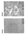
- Fig. 11 is a microscopic plan view (100,OOOxTE micrograph) of the original, virgin (i.e., unrecorded-upon) reflecting surface of a gold-island absorber film like that above-described. It will be evident that this surface appears as a physically, semi-continuous, or partly discontinuous, "insular” configuration, exhibiting a fairly regular "island” pattern (on an SiO 2 spacer-surface).
- the unwritten islands will be understood as having diameters on the order of a few hundred A° (e.g., 10-30 nm typical), separated by intervals of comparable dimension (e.g., 5-20 nm apart-vs. laser beam 500-1000 nm wide; cf 6328 nm wavelength).
- the virgin film 15 will thus exhibit a certain "% void" range (e.g., a few % to 40% voids).
- At least some of the first-order factors controlling such island formation are believed to be: absorber material, deposition-rate, adhesion; substrate material and condition (e.g., cleaning, roughness, "strike” film as “nucleation surface”) and temperature; presence of vapor-contaminants (vacuum pressure) and like factors as will be appreciated by workers.
- Figs. 12 and 13 For example, too-cool a substrate will render a continuous film, too-hot will leave no film at all.
- Figs. 12 and 13 For example, too-cool a substrate will render a continuous film, too-hot will leave no film at all.
- Figs. 12 and 13 For example, too-cool a substrate will render a continuous film, too-hot will leave no film at all.
- Figs. 12 and 13 with Fig. 11.
- a similarfilm was prepared (like Example I) except that a silica spacer was coated with a bismuth oxide layer (a "nucleation" aid known in the art).
- Fig. 13 case, a chromium nucleation layer was used. Compared with Fig. 11, the Fig. 12 seemed to exhibit thinner islands, farther apart, while Fig. 13 is a continuous gold film (no islands).
- the cited laser apparatus could not "write” at all on the film of Fig. 13 (at cited power level); while the film of Fig. 12 wrote generally as in Fig. 11 (Example I) except for a bit lower sensitivity..
- agglomeration for prescribed write/read conditions
- island temperature and "mobility” during writing (i.e., on the maximum temperature reached by "melting” islands and their associated mobility during the agglomeration phase)-these, in turn, depending on virgin-island size and “interfacial energy” of melting islands in contact with the host surface(s).
- the write-beam is assumed, here, to so affect the islands in a bit-site as to cause "agglomeration", with attendant “spherici- zation” and increase in average island size and spacing (increased % void area).
- initial (virgin) % void will be sufficient to accommodate a prescribed minimal heat loss, radially, yet not so large that initial reflectance (R o ) exceeds the desired "near zero" value (required for a "Dark Mirror")-workers will note that so-opening the absorber in a trilayer gives an effective increase in reflectivity (e.g. as here, from about 10% to about 30%).
- this writing operation may describe this writing operation as so energizing the absorber island film as to, in effect, "significantly redistribute" absorber mass at the bit site-yet not to the extent exhibited by disruptional/"deformational” (non- insular or continuous) films!
- the "so-written" film site may shift these values to about 10%-70%-20%, respectively, for the subject write wavelength (whereas the overall trilayer values would shift from 90%-0%-10% to 40-50%-0%-60-50%).
- Te Example is also run with a thin overcoating of SiO (10 nm, vapor deposited) on the (continuous) Te absorber film.
- this light SiO coat will nonetheless affect Te "pit formation", raising required write-energy to about double. (Possibly because it so restricts the Te film at the pit-site as to impede associated displacement of Te material there).
- TEM transmission electron microscope
- trilayer optical recording exemplars for TEM examination are deposited upon carbon pre-coated 200 mesh copper grids.
- the coatings consist of an aluminum reflector, dielectric spacer later and a gold absorber layer.
- An electron-transparent overcoat is also applied in select cases..
- Laser writing on such TEM specimens is carried out using a read/write system incorporating a modulated helium-neon laser.
- Read/write wavelength is 632.8 nm.
- a lens with .65 numerical aperture is used and the spot size is 0.8 micron.
- Prior to TEM examination data bits written on the TEM specimens are located using an optical microscope. This facilitates subsequent location of the written bits in the TEM.
- TEM examination is carried out using a Zeiss EM-109 electron microscope operated at 100 kilovolts. Specimen damage due to electron beam heating effects is not a problem during routine examination. With extremely high electron beam current density, however, in-situ morphological changes in the island-gold films, can be initiated; these are helpful in understanding the phenomenology of heating effects in these films.
- a gold island-film is deposited on a dielectric spacer layer (e.g., as in Example I, but omitting the reflector layer, using carbon-coated copper grid as "substrate” as above noted).
- Fig. 14 shows the so-deposited virgin (unwritten) island film.
- the reflector layer is not present in order to simplify the examination of the morphology of the as-deposited gold. The result is seen in Fig. 14, a bright field micrograph.
- the gold film evidently consists of irregularly shaped islands with an areal coverage of approximately 60 percent. Many of the islands are long and narrow in shape, while some others are roughly circular. Average island spacing is on the order of 100 A° (1 x 10- 2 p m ).
- an island metal film as the information layer in the trilayer optical storage medium is attractive for two reasons. First, the discontinuous structure of the film tends to minimize radial thermal losses during the write pulse. Second, long range surface tension forces, characteristic of media in which rim formation predominates, are absent.
- Example II is replicated, except that a full trilayer (with reflector on fluoro-polymer spacer) is produced; also light overcoating of fluoro- polymer (face “fissured”) is overlaid on the gold-island absorber. Further, a light Si0 2 strike is applied on the spacer to better "nucleate” gold isles. Then a "bit” is laser-recorded at a bit-site on this structure (10 mW, 40 ns pulse from He-Ne laser operated at 632.8 nm).
- Fig. 15 a micrograph of the so-written trilayer medium, with overcoat, demonstrates agglomeration.
- written data bit is visible in the central portion of the micrograph, while outside the written data bit, the original (virgin) island structure, similar to that shown in Fig. 14, is visible.
- the presence of the aluminum reflector layer adds an additional degree of complexity to the interpretation of this micrograph.
- This layer is polycrystalline with random crystal orientation.
- aluminum crystals suitably oriented for Bragg diffraction i.e., in contrast
- other crystals, not suitably oriented will be invisible.
- aluminum crystals in the reflector layer which are "in contrast” appear as dark areas approximately 0.1 to 0.4 microns in diameter.
- the signal to peak rms noise ratio typical of written data with the bit morphology of Fig. 15, is 30 dB over a 20 mHz bandwidth.
- the signal to peak rms noise ratio is 30 dB over a 20 mHz bandwidth.
- optical losses associated with the bit morphology shown in Fig. 15, they do not seriously degrade the optical performance of the medium.
- absence of a thick, full overcoat here is understood to enhance read-out, but only slightly-e.g., vs. read-out with full overcoat as with Fig. 2, etc.-and, vs, un- overcoated state output is degraded by about one-half-with smaller, less massive virgin isles one may expect to improve sensitivity, read-out, etc., as explained below).
- Example III is replicated with bits "written” (same laser energy) along a number of “tracks”.
- Example III is, again, replicated; except that "writing” is conducted at much reduced laser energy (up to about 1/10-1/20 that of Figs. 15, 16-more analogous to "threshold power").
- Fig. 17 indicates the "incipient" (or “threshold") agglomeration implicit in such "under-power” writing (e.g, bit formation presaging that of Figs. 15, 16). That is, here, it appears that the very low power laser pulse has brought about some change in island shape due to melting, with some spherical particles in evidence, but the agglomeration process has not gone to completion. Increased write-power will presumably give agglomeration more like that of Figs. 15, 16.
- FIGS. 14-17 demonstrate a bit formation process which is essentially one of melting and agglomeration of the island-gold film to form a distribution of spherical debris particles.
- the final size and arrangement of the debris particles should be functions of the maximum temperature which is reached by the molten islands, and of the mobility of the islands during the agglomeration phase.
- the temperature of the islands rises due to the enhanced absorption inherent to the trilayer structure.
- a melting event occurs which is accompanied by a change in shape of the islands.
- This shape change exemplified by the micrograph of Fig. 17, is driven by the increase in "interfacial energy" for the now-molten gold at the spacer and overcoat interfaces.
- a consequence of the shape change is the initiation of a "detuning" of the optical absorption of the trilayer, which is accompanied by a. decrease in the rate of temperature rise.
- the temperature at which the melting event occurs is thought to be in the range of 300°C. to 600°C., well below the bulk melting temperature of gold.
- the minimum laser write power necessary to bring the island-gold to the critical temperature required for melting, with the shape change and trilayer detuning which accompany it, may be understood as the "threshold" power for a given medium.
- the threshold power for media which have a high threshold power, island temperatures are high prior to the initiation of melting and detuning of the trilayer.
- Example IV of bit formation in such a medium is shown in Fig. 18, which is a TEM micrograph of a trilayer with an island-gold information layer, written with a 10 mW, 40 ns laser pulse.
- Fig. 18 is a TEM micrograph of a trilayer with an island-gold information layer, written with a 10 mW, 40 ns laser pulse.
- Fig. 18 sample, or Example IV may be understood as essentially the same as that of Fig. 15, except that a tin strike is substituted for the Si0 2 strike-thus, in light of the indicated "Massive agglomeration" of Fig. 18, with fewer, larger globs, non-uniformly distributed (by same write-energy), one might characterize a Sn-strike, or nucleating film, as "high threshold-high noise" where the Si0 2 strike could be characterized as “low threshold-low noise” for such gold absorbers-see further below).
- Massive agglomeration is presumably inhibited by the subject "contact-faces" (e.g., channels in fluoro-polymer overcoat evidently don't “freely pass” these), one will assume that other, more-widely-fissured contact faces will inhibit it less (cf. improvement feature).
- contact-faces e.g., channels in fluoro-polymer overcoat evidently don't “freely pass” these
- Example V (Fig. 19), same as for Fig. 15 except spacer is another modified fluoro- polymer and has no nucleation film thereon.
- a characteristic of media with low thresholds is increased bit diameter for a given write power, as compared to media with high thresholds. Due to their lower temperature for melting and optical detuning of the trilayer, low threshold media more effectively utilize the outer, lower power regions of the incident Gaussian beam.
- Example V (Fig. 19) may be characterized as "Low Threshold” (low noise), yet still lacking in full complete agglomeration.
- Low Threshold low noise
- AR reflectance shift
- bit formation mechanism described above does not involve mass transport over long distances. It involves localized rearrangements of the gold islands which do not necessitate large displacements of adjacent surfaces. As the gold islands cover only approximately 60 percent of the available area, ample space exists to accommodate this rearrangement. Of course, there must be limits to the extent to which the agglomeration process can proceed without being affected by a massive overcoat.
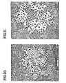
- Example 11 is replicated except that the Si0 2 "strike” on the spacer (nucleating strike) is replaced by another, “low-threshold” material, but one fostering better, more complete agglomeration-and inducing smaller, reduced- mass virgin islands; and processed accordingly.
- island deposition evidently (see TEM Fig. 20, showing an as-written "bit- "-magnified 2x in Fig. 21) yields the smallest islands (least mass, smallest diameter) on the average, of all Examples herein. This evidently due (in part, at least) to the superior nucleation- film used.
- this sample yields superior agglomeration and other writing effects (bit-formation; e.g., vs. samples of Fig. 15, or Fig. 19, etc., when similarly written-upon).
- the diameter of the as-deposited (virgin) gold islands is extremely small, averaging approximately 80 A°.
- the data bit (Fig. 20, center), written with a 10 mW, 40 ns laser pulse, exhibits a highly uniform distribution of spherical debris particles. Incipient melting and agglomeration effects, visible at the edge of the written bit, delineate a "threshold region".
- Fig. 21 a micrograph of anothee like written data bit in the same medium (and same write-energy, etc.) shows this "threshold region” at higher magnification. Also, here, the associated “contact surfaces” evidently accommodate, or induce, "small-glob” incipient agglomeration (more, smaller globs), typical of a “moderate to low threshold” surface (cf. same fissed fluoro- polymer overcoat as before).
- interfacial energy (of melting gold in contact with surrounding surfaces) is important in two respects. First, it is the increase in interfacial energy, upon melting, which causes the gold islands to assume their spherical shape (they tend to minimize surface area per unit volume). Any increase in surface energy, therefore, represents a barrier to melting and will effectively raise the "threshold temperature" at which trilayer-detuning commences.
- bit-formation (agglomeration) mechanism here proposed for trilayer media incorporating island-gold as the information layer is believed to consist of two stages: melting, then agglomeration; that is:
- the effective temperature at which melting and trilayer-detuning occur is determined by "interfacial energy differences" between the solid and liquid states (of gold) in contact with the host (spacer, overcoat) surfaces. This effective melting temperature is thought to be well below the bulk melting temperature of gold.
- the shape change associated with island melting is a consequence of an increase in interfacial energy with the change from solid to molten gold in contact with the host surfaces.
- the gold islands irregular in shape as-deposited, revert to tiny spheres, thereby minimizing contact area at the (presumed) high energy interfaces.
- the driving force for agglomeration of the molten gold islands is the decrease in surface energy per unit volume represented by the change from a configuration of many tiny particles to a configuration of few large particles.
- the mobility of molten islands during the agglomeration phase is a function of their temperature and their size. Small islands utilize available passages at the spacer/overcoat interface more efficiently than large islands, and are thus more mobile. High temperatures imply a longer migration lifetime, thus prolonging the time available for agglomeration prior to solidification (cooling, which the de-tuning encourages, of course).
Landscapes
- Optical Record Carriers And Manufacture Thereof (AREA)
- Thermal Transfer Or Thermal Recording In General (AREA)
Applications Claiming Priority (2)
| Application Number | Priority Date | Filing Date | Title |
|---|---|---|---|
| US54023083A | 1983-10-11 | 1983-10-11 | |
| US540230 | 1983-10-11 |
Publications (2)
| Publication Number | Publication Date |
|---|---|
| EP0139507A1 EP0139507A1 (en) | 1985-05-02 |
| EP0139507B1 true EP0139507B1 (en) | 1989-05-24 |
Family
ID=24154559
Family Applications (1)
| Application Number | Title | Priority Date | Filing Date |
|---|---|---|---|
| EP84306861A Expired EP0139507B1 (en) | 1983-10-11 | 1984-10-09 | Island record films; fabrication |
Country Status (4)
| Country | Link |
|---|---|
| EP (1) | EP0139507B1 (ja) |
| JP (1) | JPS61500138A (ja) |
| DE (1) | DE3478362D1 (ja) |
| WO (1) | WO1985001822A1 (ja) |
Families Citing this family (2)
| Publication number | Priority date | Publication date | Assignee | Title |
|---|---|---|---|---|
| IL91213A0 (en) * | 1988-08-11 | 1990-03-19 | Dow Chemical Co | Discontinuous film optical storage media |
| AT397736B (de) * | 1992-08-11 | 1994-06-27 | Aussenegg Franz Rembert Dr | Optisches datenspeichermedium |
Citations (1)
| Publication number | Priority date | Publication date | Assignee | Title |
|---|---|---|---|---|
| EP0083391A2 (de) * | 1981-09-29 | 1983-07-13 | Bayer Ag | Reifen für Kraftfahrzeuge |
Family Cites Families (7)
| Publication number | Priority date | Publication date | Assignee | Title |
|---|---|---|---|---|
| WO1983001699A1 (en) * | 1981-11-09 | 1983-05-11 | Burroughs Corp | Archival data recording system using low power radiation and related media |
| JPS58501885A (ja) * | 1981-11-09 | 1983-11-04 | バロ−ス・コ−ポレ−ション | ディジタルデ−タストレ−ジのための記録保管記録媒体のための形成技術 |
| EP0083396A1 (en) * | 1981-12-31 | 1983-07-13 | International Business Machines Corporation | An optical storage medium |
| US4451915A (en) * | 1982-04-15 | 1984-05-29 | Burroughs Corporation | Optical storage system employing a multi-layer optical medium |
| US4451914A (en) * | 1982-04-15 | 1984-05-29 | Burroughs Corporation | Optical storage system employing a multi-layer optical medium |
| EP0096501B1 (en) * | 1982-05-25 | 1988-11-09 | Unisys Corporation | Method for detecting fire |
| DE3376238D1 (en) * | 1982-05-25 | 1988-05-11 | Unisys Corp | Archival record films for digital data storage using low power write-laser |
-
1984
- 1984-10-09 EP EP84306861A patent/EP0139507B1/en not_active Expired
- 1984-10-09 DE DE8484306861T patent/DE3478362D1/de not_active Expired
- 1984-10-10 WO PCT/US1984/001600 patent/WO1985001822A1/en unknown
- 1984-10-10 JP JP59503938A patent/JPS61500138A/ja active Pending
Patent Citations (1)
| Publication number | Priority date | Publication date | Assignee | Title |
|---|---|---|---|---|
| EP0083391A2 (de) * | 1981-09-29 | 1983-07-13 | Bayer Ag | Reifen für Kraftfahrzeuge |
Also Published As
| Publication number | Publication date |
|---|---|
| WO1985001822A1 (en) | 1985-04-25 |
| EP0139507A1 (en) | 1985-05-02 |
| DE3478362D1 (en) | 1989-06-29 |
| JPS61500138A (ja) | 1986-01-23 |
Similar Documents
| Publication | Publication Date | Title |
|---|---|---|
| EP0092113B1 (en) | Optical recording medium for use in an optical storage system and method for making such recording medium | |
| EP0139507B1 (en) | Island record films; fabrication | |
| EP0079231B1 (en) | Optical recording method for archival digital data storage | |
| EP0096504B1 (en) | Aurous archival record films for digital data storage | |
| EP0098046B1 (en) | Archival record films for digital data storage using low power write-laser | |
| EP0098045B1 (en) | Gold archival record films for digital data storage using low power write-laser | |
| EP0096501B1 (en) | Method for detecting fire | |
| EP0079229B1 (en) | Apparatus for recording digital data on an archival optical data storage medium using low power radiation | |
| EP0096503A2 (en) | Heat sensitive film shutter | |
| US5177732A (en) | Optical recording using an agglomerating recording medium which changes reflectivity upon recording | |
| EP0097430B1 (en) | Method for detecting fire | |
| EP0079741B1 (en) | Archival recording media with improved information layer and associated substrate | |
| EP0362901A2 (en) | Heat sensitive film shutter | |
| EP0079230A2 (en) | Preparation of archival recording media for digital data storage | |
| EP0096502A1 (en) | Insular insulated record films for digital data storage using low power write-laser | |
| EP0079233A2 (en) | Method of archival data recording and related media | |
| EP0079232A2 (en) | Archival data recording system using low power radiation and related media | |
| Holstein et al. | Mechanism of laser writing for optical data storage in an overcoated tellurium alloy trilayer | |
| EP0189462A1 (en) | Optical storage structure | |
| JPS59500439A (ja) | 低出力書込レ−ザを用いるディジタル・デ−タ・ストレ−ジに適した記録保存フィルム | |
| JPS59500886A (ja) | ディジタル・デ−タ・ストレ−ジに適した第1金の記録保存フィルム | |
| JPS59500438A (ja) | 低出力書込レ−ザを用いるディジタル・デ−タ・ストレ−ジに適した金記録保存フィルム | |
| JPS59500883A (ja) | 低出力書込レ−ザを用いるディジタル・デ−タ・ストレ−ジに適した金合金記録保存フィルム | |
| JPS59500887A (ja) | 感熱性フィルムシャッタ | |
| JPS59500991A (ja) | ディジタル・デ−タ・ストレ−ジに適したアイランド状の記録フィルム |
Legal Events
| Date | Code | Title | Description |
|---|---|---|---|
| PUAI | Public reference made under article 153(3) epc to a published international application that has entered the european phase |
Free format text: ORIGINAL CODE: 0009012 |
|
| 17P | Request for examination filed |
Effective date: 19841015 |
|
| AK | Designated contracting states |
Designated state(s): BE DE FR GB NL SE |
|
| 17Q | First examination report despatched |
Effective date: 19860723 |
|
| D17Q | First examination report despatched (deleted) | ||
| RAP1 | Party data changed (applicant data changed or rights of an application transferred) |
Owner name: UNISYS CORPORATION |
|
| GRAA | (expected) grant |
Free format text: ORIGINAL CODE: 0009210 |
|
| AK | Designated contracting states |
Kind code of ref document: B1 Designated state(s): BE DE FR GB NL SE |
|
| REF | Corresponds to: |
Ref document number: 3478362 Country of ref document: DE Date of ref document: 19890629 |
|
| ET | Fr: translation filed | ||
| PLBE | No opposition filed within time limit |
Free format text: ORIGINAL CODE: 0009261 |
|
| STAA | Information on the status of an ep patent application or granted ep patent |
Free format text: STATUS: NO OPPOSITION FILED WITHIN TIME LIMIT |
|
| 26N | No opposition filed | ||
| PGFP | Annual fee paid to national office [announced via postgrant information from national office to epo] |
Ref country code: SE Payment date: 19900928 Year of fee payment: 7 |
|
| PGFP | Annual fee paid to national office [announced via postgrant information from national office to epo] |
Ref country code: GB Payment date: 19901001 Year of fee payment: 7 |
|
| PGFP | Annual fee paid to national office [announced via postgrant information from national office to epo] |
Ref country code: FR Payment date: 19901022 Year of fee payment: 7 |
|
| PGFP | Annual fee paid to national office [announced via postgrant information from national office to epo] |
Ref country code: DE Payment date: 19901026 Year of fee payment: 7 |
|
| PGFP | Annual fee paid to national office [announced via postgrant information from national office to epo] |
Ref country code: NL Payment date: 19901031 Year of fee payment: 7 |
|
| PGFP | Annual fee paid to national office [announced via postgrant information from national office to epo] |
Ref country code: BE Payment date: 19910116 Year of fee payment: 7 |
|
| PG25 | Lapsed in a contracting state [announced via postgrant information from national office to epo] |
Ref country code: GB Effective date: 19911009 |
|
| PG25 | Lapsed in a contracting state [announced via postgrant information from national office to epo] |
Ref country code: SE Effective date: 19911010 |
|
| PG25 | Lapsed in a contracting state [announced via postgrant information from national office to epo] |
Ref country code: BE Effective date: 19911031 |
|
| BERE | Be: lapsed |
Owner name: UNISYS CORP. Effective date: 19911031 |
|
| PG25 | Lapsed in a contracting state [announced via postgrant information from national office to epo] |
Ref country code: NL Effective date: 19920501 |
|
| GBPC | Gb: european patent ceased through non-payment of renewal fee | ||
| NLV4 | Nl: lapsed or anulled due to non-payment of the annual fee | ||
| PG25 | Lapsed in a contracting state [announced via postgrant information from national office to epo] |
Ref country code: FR Effective date: 19920630 |
|
| PG25 | Lapsed in a contracting state [announced via postgrant information from national office to epo] |
Ref country code: DE Effective date: 19920701 |
|
| REG | Reference to a national code |
Ref country code: FR Ref legal event code: ST |
|
| EUG | Se: european patent has lapsed |
Ref document number: 84306861.0 Effective date: 19920510 |