EP0139434B1 - Thermophotovoltaic technology - Google Patents
Thermophotovoltaic technology Download PDFInfo
- Publication number
- EP0139434B1 EP0139434B1 EP84306033A EP84306033A EP0139434B1 EP 0139434 B1 EP0139434 B1 EP 0139434B1 EP 84306033 A EP84306033 A EP 84306033A EP 84306033 A EP84306033 A EP 84306033A EP 0139434 B1 EP0139434 B1 EP 0139434B1
- Authority
- EP
- European Patent Office
- Prior art keywords
- mantle
- peak
- flux
- further characterized
- less
- Prior art date
- Legal status (The legal status is an assumption and is not a legal conclusion. Google has not performed a legal analysis and makes no representation as to the accuracy of the status listed.)
- Expired - Lifetime
Links
- 238000005516 engineering process Methods 0.000 title description 2
- 230000004907 flux Effects 0.000 claims description 70
- 230000005855 radiation Effects 0.000 claims description 49
- 230000003595 spectral effect Effects 0.000 claims description 39
- 239000000446 fuel Substances 0.000 claims description 31
- XUIMIQQOPSSXEZ-UHFFFAOYSA-N Silicon Chemical compound [Si] XUIMIQQOPSSXEZ-UHFFFAOYSA-N 0.000 claims description 21
- 229910052710 silicon Inorganic materials 0.000 claims description 21
- 239000010703 silicon Substances 0.000 claims description 21
- NNPPMTNAJDCUHE-UHFFFAOYSA-N isobutane Chemical compound CC(C)C NNPPMTNAJDCUHE-UHFFFAOYSA-N 0.000 claims description 20
- 239000001282 iso-butane Substances 0.000 claims description 17
- ATUOYWHBWRKTHZ-UHFFFAOYSA-N Propane Chemical compound CCC ATUOYWHBWRKTHZ-UHFFFAOYSA-N 0.000 claims description 16
- 238000006243 chemical reaction Methods 0.000 claims description 16
- 239000000835 fiber Substances 0.000 claims description 14
- 238000004519 manufacturing process Methods 0.000 claims description 9
- 239000001294 propane Substances 0.000 claims description 9
- 229910001404 rare earth metal oxide Inorganic materials 0.000 claims description 9
- 229910052732 germanium Inorganic materials 0.000 claims description 7
- GNPVGFCGXDBREM-UHFFFAOYSA-N germanium atom Chemical compound [Ge] GNPVGFCGXDBREM-UHFFFAOYSA-N 0.000 claims description 7
- 239000001257 hydrogen Substances 0.000 claims description 7
- 229910052739 hydrogen Inorganic materials 0.000 claims description 7
- 239000007788 liquid Substances 0.000 claims description 5
- 229910044991 metal oxide Inorganic materials 0.000 claims description 5
- 150000004706 metal oxides Chemical class 0.000 claims description 5
- 229910052691 Erbium Inorganic materials 0.000 claims description 4
- 229910052769 Ytterbium Inorganic materials 0.000 claims description 4
- UYAHIZSMUZPPFV-UHFFFAOYSA-N erbium Chemical compound [Er] UYAHIZSMUZPPFV-UHFFFAOYSA-N 0.000 claims description 4
- 238000002955 isolation Methods 0.000 claims description 4
- VNWKTOKETHGBQD-UHFFFAOYSA-N methane Chemical compound C VNWKTOKETHGBQD-UHFFFAOYSA-N 0.000 claims description 4
- NAWDYIZEMPQZHO-UHFFFAOYSA-N ytterbium Chemical compound [Yb] NAWDYIZEMPQZHO-UHFFFAOYSA-N 0.000 claims description 4
- 229910052751 metal Inorganic materials 0.000 claims description 3
- 239000002184 metal Substances 0.000 claims description 3
- 229910052689 Holmium Inorganic materials 0.000 claims description 2
- 239000001273 butane Substances 0.000 claims description 2
- 239000003502 gasoline Substances 0.000 claims description 2
- KJZYNXUDTRRSPN-UHFFFAOYSA-N holmium atom Chemical compound [Ho] KJZYNXUDTRRSPN-UHFFFAOYSA-N 0.000 claims description 2
- 230000007246 mechanism Effects 0.000 claims description 2
- IJDNQMDRQITEOD-UHFFFAOYSA-N n-butane Chemical compound CCCC IJDNQMDRQITEOD-UHFFFAOYSA-N 0.000 claims description 2
- OFBQJSOFQDEBGM-UHFFFAOYSA-N n-pentane Natural products CCCCC OFBQJSOFQDEBGM-UHFFFAOYSA-N 0.000 claims description 2
- 239000003345 natural gas Substances 0.000 claims description 2
- 125000004435 hydrogen atom Chemical class [H]* 0.000 claims 1
- 229920000297 Rayon Polymers 0.000 description 15
- 239000004744 fabric Substances 0.000 description 15
- 239000002964 rayon Substances 0.000 description 13
- ZXGIFJXRQHZCGJ-UHFFFAOYSA-N erbium(3+);oxygen(2-) Chemical compound [O-2].[O-2].[O-2].[Er+3].[Er+3] ZXGIFJXRQHZCGJ-UHFFFAOYSA-N 0.000 description 10
- VQCBHWLJZDBHOS-UHFFFAOYSA-N erbium(III) oxide Inorganic materials O=[Er]O[Er]=O VQCBHWLJZDBHOS-UHFFFAOYSA-N 0.000 description 10
- 239000000463 material Substances 0.000 description 7
- 239000000203 mixture Substances 0.000 description 6
- 230000003287 optical effect Effects 0.000 description 6
- 238000000034 method Methods 0.000 description 5
- KUBYTSCYMRPPAG-UHFFFAOYSA-N ytterbium(3+);trinitrate Chemical compound [Yb+3].[O-][N+]([O-])=O.[O-][N+]([O-])=O.[O-][N+]([O-])=O KUBYTSCYMRPPAG-UHFFFAOYSA-N 0.000 description 5
- IJGRMHOSHXDMSA-UHFFFAOYSA-N Atomic nitrogen Chemical compound N#N IJGRMHOSHXDMSA-UHFFFAOYSA-N 0.000 description 4
- 229910002651 NO3 Inorganic materials 0.000 description 4
- NHNBFGGVMKEFGY-UHFFFAOYSA-N Nitrate Chemical compound [O-][N+]([O-])=O NHNBFGGVMKEFGY-UHFFFAOYSA-N 0.000 description 4
- KZHJGOXRZJKJNY-UHFFFAOYSA-N dioxosilane;oxo(oxoalumanyloxy)alumane Chemical compound O=[Si]=O.O=[Si]=O.O=[Al]O[Al]=O.O=[Al]O[Al]=O.O=[Al]O[Al]=O KZHJGOXRZJKJNY-UHFFFAOYSA-N 0.000 description 4
- 229910052863 mullite Inorganic materials 0.000 description 4
- 238000007493 shaping process Methods 0.000 description 4
- ZCUFMDLYAMJYST-UHFFFAOYSA-N thorium dioxide Chemical compound O=[Th]=O ZCUFMDLYAMJYST-UHFFFAOYSA-N 0.000 description 4
- 229910001369 Brass Inorganic materials 0.000 description 3
- QVGXLLKOCUKJST-UHFFFAOYSA-N atomic oxygen Chemical compound [O] QVGXLLKOCUKJST-UHFFFAOYSA-N 0.000 description 3
- 239000010951 brass Substances 0.000 description 3
- 238000005119 centrifugation Methods 0.000 description 3
- 239000001301 oxygen Substances 0.000 description 3
- 229910052760 oxygen Inorganic materials 0.000 description 3
- 101100421916 Arabidopsis thaliana SOT5 gene Proteins 0.000 description 2
- UFHFLCQGNIYNRP-UHFFFAOYSA-N Hydrogen Chemical compound [H][H] UFHFLCQGNIYNRP-UHFFFAOYSA-N 0.000 description 2
- 235000019687 Lamb Nutrition 0.000 description 2
- 238000013019 agitation Methods 0.000 description 2
- 229910052782 aluminium Inorganic materials 0.000 description 2
- XAGFODPZIPBFFR-UHFFFAOYSA-N aluminium Chemical compound [Al] XAGFODPZIPBFFR-UHFFFAOYSA-N 0.000 description 2
- HSJPMRKMPBAUAU-UHFFFAOYSA-N cerium(3+);trinitrate Chemical compound [Ce+3].[O-][N+]([O-])=O.[O-][N+]([O-])=O.[O-][N+]([O-])=O HSJPMRKMPBAUAU-UHFFFAOYSA-N 0.000 description 2
- 229910000422 cerium(IV) oxide Inorganic materials 0.000 description 2
- 239000011248 coating agent Substances 0.000 description 2
- 238000000576 coating method Methods 0.000 description 2
- 238000001816 cooling Methods 0.000 description 2
- 238000010304 firing Methods 0.000 description 2
- 239000007789 gas Substances 0.000 description 2
- 238000010438 heat treatment Methods 0.000 description 2
- 238000005213 imbibition Methods 0.000 description 2
- 229910052757 nitrogen Inorganic materials 0.000 description 2
- 239000007800 oxidant agent Substances 0.000 description 2
- 230000001590 oxidative effect Effects 0.000 description 2
- 230000035515 penetration Effects 0.000 description 2
- 230000008569 process Effects 0.000 description 2
- 229910052761 rare earth metal Inorganic materials 0.000 description 2
- 150000002910 rare earth metals Chemical class 0.000 description 2
- 230000004044 response Effects 0.000 description 2
- 238000002791 soaking Methods 0.000 description 2
- 229940007392 tylan Drugs 0.000 description 2
- WBPYTXDJUQJLPQ-VMXQISHHSA-N tylosin Chemical compound O([C@@H]1[C@@H](C)O[C@H]([C@@H]([C@H]1N(C)C)O)O[C@@H]1[C@@H](C)[C@H](O)CC(=O)O[C@@H]([C@H](/C=C(\C)/C=C/C(=O)[C@H](C)C[C@@H]1CC=O)CO[C@H]1[C@@H]([C@H](OC)[C@H](O)[C@@H](C)O1)OC)CC)[C@H]1C[C@@](C)(O)[C@@H](O)[C@H](C)O1 WBPYTXDJUQJLPQ-VMXQISHHSA-N 0.000 description 2
- 235000019375 tylosin Nutrition 0.000 description 2
- XLYOFNOQVPJJNP-UHFFFAOYSA-N water Chemical compound O XLYOFNOQVPJJNP-UHFFFAOYSA-N 0.000 description 2
- OKTJSMMVPCPJKN-UHFFFAOYSA-N Carbon Chemical compound [C] OKTJSMMVPCPJKN-UHFFFAOYSA-N 0.000 description 1
- 239000004215 Carbon black (E152) Substances 0.000 description 1
- RYGMFSIKBFXOCR-UHFFFAOYSA-N Copper Chemical compound [Cu] RYGMFSIKBFXOCR-UHFFFAOYSA-N 0.000 description 1
- 229910052779 Neodymium Inorganic materials 0.000 description 1
- 241000872198 Serjania polyphylla Species 0.000 description 1
- BQCADISMDOOEFD-UHFFFAOYSA-N Silver Chemical compound [Ag] BQCADISMDOOEFD-UHFFFAOYSA-N 0.000 description 1
- 239000004115 Sodium Silicate Substances 0.000 description 1
- 239000004809 Teflon Substances 0.000 description 1
- 229920006362 Teflon® Polymers 0.000 description 1
- 229920004890 Triton X-100 Polymers 0.000 description 1
- 239000013504 Triton X-100 Substances 0.000 description 1
- 229910052799 carbon Inorganic materials 0.000 description 1
- 230000036755 cellular response Effects 0.000 description 1
- 230000008859 change Effects 0.000 description 1
- 239000003153 chemical reaction reagent Substances 0.000 description 1
- 239000000567 combustion gas Substances 0.000 description 1
- 238000002485 combustion reaction Methods 0.000 description 1
- 238000004891 communication Methods 0.000 description 1
- 238000010276 construction Methods 0.000 description 1
- 229910052802 copper Inorganic materials 0.000 description 1
- 239000010949 copper Substances 0.000 description 1
- 238000000354 decomposition reaction Methods 0.000 description 1
- 230000007547 defect Effects 0.000 description 1
- 238000010586 diagram Methods 0.000 description 1
- 239000012153 distilled water Substances 0.000 description 1
- 238000009826 distribution Methods 0.000 description 1
- YBYGDBANBWOYIF-UHFFFAOYSA-N erbium(3+);trinitrate Chemical compound [Er+3].[O-][N+]([O-])=O.[O-][N+]([O-])=O.[O-][N+]([O-])=O YBYGDBANBWOYIF-UHFFFAOYSA-N 0.000 description 1
- 230000005284 excitation Effects 0.000 description 1
- 239000011521 glass Substances 0.000 description 1
- 239000003779 heat-resistant material Substances 0.000 description 1
- 239000011796 hollow space material Substances 0.000 description 1
- 229930195733 hydrocarbon Natural products 0.000 description 1
- 150000002430 hydrocarbons Chemical class 0.000 description 1
- 150000002431 hydrogen Chemical class 0.000 description 1
- 238000005259 measurement Methods 0.000 description 1
- 238000012544 monitoring process Methods 0.000 description 1
- QEFYFXOXNSNQGX-UHFFFAOYSA-N neodymium atom Chemical compound [Nd] QEFYFXOXNSNQGX-UHFFFAOYSA-N 0.000 description 1
- 239000011368 organic material Substances 0.000 description 1
- 239000004033 plastic Substances 0.000 description 1
- 229920003023 plastic Polymers 0.000 description 1
- 238000005036 potential barrier Methods 0.000 description 1
- 238000010248 power generation Methods 0.000 description 1
- 239000002243 precursor Substances 0.000 description 1
- 229910052709 silver Inorganic materials 0.000 description 1
- 239000004332 silver Substances 0.000 description 1
- NTHWMYGWWRZVTN-UHFFFAOYSA-N sodium silicate Chemical compound [Na+].[Na+].[O-][Si]([O-])=O NTHWMYGWWRZVTN-UHFFFAOYSA-N 0.000 description 1
- 229910052911 sodium silicate Inorganic materials 0.000 description 1
- 125000006850 spacer group Chemical group 0.000 description 1
- 238000001228 spectrum Methods 0.000 description 1
- 238000003860 storage Methods 0.000 description 1
- 230000001629 suppression Effects 0.000 description 1
- 239000004753 textile Substances 0.000 description 1
- 238000009423 ventilation Methods 0.000 description 1
- 230000000007 visual effect Effects 0.000 description 1
- 239000000080 wetting agent Substances 0.000 description 1
Images
Classifications
-
- F—MECHANICAL ENGINEERING; LIGHTING; HEATING; WEAPONS; BLASTING
- F21—LIGHTING
- F21H—INCANDESCENT MANTLES; OTHER INCANDESCENT BODIES HEATED BY COMBUSTION
- F21H1/00—Incandescent mantles; Selection of imbibition liquids therefor
- F21H1/02—Incandescent mantles; Selection of imbibition liquids therefor characterised by the material thereof
-
- H—ELECTRICITY
- H02—GENERATION; CONVERSION OR DISTRIBUTION OF ELECTRIC POWER
- H02S—GENERATION OF ELECTRIC POWER BY CONVERSION OF INFRARED RADIATION, VISIBLE LIGHT OR ULTRAVIOLET LIGHT, e.g. USING PHOTOVOLTAIC [PV] MODULES
- H02S10/00—PV power plants; Combinations of PV energy systems with other systems for the generation of electric power
- H02S10/30—Thermophotovoltaic systems
-
- Y—GENERAL TAGGING OF NEW TECHNOLOGICAL DEVELOPMENTS; GENERAL TAGGING OF CROSS-SECTIONAL TECHNOLOGIES SPANNING OVER SEVERAL SECTIONS OF THE IPC; TECHNICAL SUBJECTS COVERED BY FORMER USPC CROSS-REFERENCE ART COLLECTIONS [XRACs] AND DIGESTS
- Y02—TECHNOLOGIES OR APPLICATIONS FOR MITIGATION OR ADAPTATION AGAINST CLIMATE CHANGE
- Y02E—REDUCTION OF GREENHOUSE GAS [GHG] EMISSIONS, RELATED TO ENERGY GENERATION, TRANSMISSION OR DISTRIBUTION
- Y02E10/00—Energy generation through renewable energy sources
- Y02E10/50—Photovoltaic [PV] energy
Definitions
- thermophotovoltaic device containing a radiation source and more particularly a source of the thermally excited type in which radiation is emitted from a heated element.
- Radiation sources of the thermally excited type such as incandescent lamps in which light is emitted from a highly heated resistance wire and incandescent mantles of the Welsbach type have long been known.
- Such radiation sources generally have characteristics of the "black body”, or more realistically “gray body”, type and emit radiation over a broad spectral band.
- photocell conversion efficiency is a function of the band gap (in electron volts) and the temperature of the particular photocell material.
- silicon which has a band gap of about 1.1 electron volts, equivalent to a wavelength of about 1150 nanometers
- germanium which has a band gap of about 0.7 electron volt, equivalent to a wavelength of about 1800 nanometers.
- thermophotovoltaic device In a thermophotovoltaic device, a close match between the spectrum of photon energy radiated from the radiation source and the electron production threshold of the photovoltaic cell results in a greater amount of energy which is absorbed by the photovoltaic cell boning converted to electrical energy and a minimal amount being converted to heat.
- Silicon photovoltaic cells have relatively low conversion efficiency in direct sunlight, in part because the specific spectral energy of solar radiation does not provide a good spectral match with the response of a silicon photovoltaic cell as that portion of solar radiation with wavelengths longer than 1100 nanometers is useless to the silicon cell photovoltaic conversion process and generates heat in the cell requiring an increased effort for cooling to keep the cell at its best performance, and as the maximum spectral radiance in sunlight occurs at about 500 nanometers which corresponds to a photon energy of 2.5 electron volts, while only 1.1 electron volts are required to produce the hole-electron pairs in silicon which contribute to external current flow and power output.
- thermophotovoltaic energy conversion systems have been proposed for use in thermophotovoltaic energy conversion systems, such uses are not particularly efficient as such mantles generate substantial amounts of radiation throughout a spectral region that extends from the visible well into the infrared.
- Other proposed thermophotovoltaic energy conversions systems have used reflector and rare earth active filter arrangements (see e.g. US-A-3 751 303, US-A-3 929 510).
- thermophotovoltaic device with a narrow band thermal emitter.
- thermophotovoltaic device as featured in claim 1 and in particular containing a thermally excited radiation source with a narrow peak in the spectral profile of its radiated flux and skirt portions of the radiated flux profile on either side of the narrow peak being suppressed so that the emitted radiation has a concentrated spectral distribution.
- the rare earth oxide radiator member of the narrow band thermally energized radiation source has a cross-sectional dimension in the range of five to thirty micrometers, and that rare earth oxide radiator member, when heated to about 1700°C, has a concentrated radiated flux over the 400-2500 nanometer wavelength range such that at least 50% of the radiated flux is within a spectral band that is less than 400 nanometers wide.
- the radiation source may be thermally excited by various techniques including, for example, electrical energy or liquid or gaseous fuels such as hydrogen, natural gas, propane, butane, isobutane or gasoline.
- the narrow band thermally excited radiation source is composed of interlocked fibers of at least one oxide of a host rare earth metal selected from a class consisting of erbium, holmium, neodymium and ytterbium, the radiated flux of the radiation source having a full width at half maximum (at 1/2 the maximum radiated flux of the source) of less than 400 nanometers.
- the relative spectral irradiance profiles of preferred radiators also have suppressed skirt characteristics such that at wavelengths 500 nanometers above and below the peak wavelength, the skirts have radiated fluxes that are less than ten and more preferably less than five percent of the profile peak radiated flux.
- the radiation source is a self-supporting rare earth oxide fiber mantle that defines a hollow space, and that is secured on a support tube by an integral shrunken skirt portion.
- thermophotovoltaic device that includes a photocell and a radiator of rare earth metal oxide material disposed in optically coupled relation to the photocell.
- thermophotovoltaic devices may be used in power generation, topping cycles, cogeneration, or communication applications, for example.
- the radiator and photocell may be close coupled, for example in the same housing, or spaced apart with the radiation from the radiator focused on the more remotely located photocell, or coupled as by means of fiber optic technology.
- thermophotovoltaic device also includes means for thermally exciting the radiator to cause it to emit radiation in a spectral irradiance profile that has a radiated flux peak with a full width at half maximum of less than 400 nanometers, the radiated flux peak being less than 400 nanometers below (on the higher energy side of) the electron production threshold of the photocell.
- the photon conversion efficiency of preferred thermophotovoltaic devices is more than fifty percent.
- a radiator of rare earth metal oxide material is thermally excited at a temperature in the range of 1500 - 2000°C to cause the radiator to emit radiation in a spectral irradiance profile that has a narrow radiated flux peak that has a full width at half maximum of less than 400 nanometers and preferably less than 200 nanometers, and suppressed skirt characteristics such that at wavelengths in the range of 300 - 500 nanometers above and below the flux peak, the radiated flux levels of the skirts are less than ten and preferably less than five percent of the peak radiated flux.
- the thermal excitation system includes a liquid hydrocarbon fuel supply, a conduit connected to the fuel supply that has an outlet port aligned with the rare earth metal oxide radiator, a fuel control for controlling the flow of fuel through the conduit to the radiator, and an igniter mechanism for igniting the fuel.
- radiators are self-supporting rare earth metal oxide fiber mantles that are composed of metal oxide multi-filament strands with cross-sectional strand dimensions in the range of 0.05 - 0.3 millimeter and filament cross-sectional dimensions in the range of five to thirty micrometers.
- a reflector system may advantageously be employed for collecting, directing and concentrating the radiated flux from the mantle to the photocell, and radiation transmitting thermal isolation structure may be positioned between the mantle (or mantles) of the radiation source and the photovoltaic cell array.
- Particularly useful thermophotovoltaic devices include an ytterbia mantle coupled to a silicon type photocell and an erbia mantle coupled to a germanium type photocell.
- Mantle arrangements such as multiple mantles or mantles of more complex geometry such as pleated structures that are designed to radiate more energy without a corresponding increase in convection loss may also be employed in thermophotovoltaic devices in accordance with the invention. Additional efficiency enhancement may be obtained by a regenerator through which the hot convection gas is routed to warm the incoming combustion air.
- Incandescent mantles as used in the present invention are described in EP-A-0101086 which belongs to the state of the art according to Art 54(3)EPC.
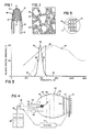
- FIG. 1 shows a radiation source 10 of the mantle type that is mounted on support tube 12 of mullite or other suitable heat resistant material.
- Support tube 12 has an outer diameter of about five millimeters and an inner diameter of about three millimeters.
- Mantle 10 is a self-supporting ytterbia fiber fabric structure that defines a hollow chamber 14 of about seventy cubic millimeters volume with tip 16 about 1/2 centimeter above the upper end surface 18 of support tube 12.
- the lower portion 20 of the mantle fabric is about 1/2 centimeter in length and is firmly shrink-secured to the outer surface of support tube 12.
- the mantle fabric is formed of ytterbia multi-filament strands 22 in an open knit array with openings 24 such that the open area of the fabric is about 60%.
- the cross-sectional dimensions of the individual ytterbia filaments 26 (Fig. 2) of strands 22 are in the range of about five-ten micrometers, and the strands 22 have cross-sectional dimensions in the order of about 0.1 millimeter with openings 24 having dimensions of about 0.5 millimeter.
- a process for manufacturing mantle 10 is as follows. Continuous low twist, low tenacity (highly reticulated), viscose rayon yarn (150 denier/60 filament) is knitted into a continuous tubular sleeve using a Lamb circular string knitter (Model ST3A/ZA) with a 2.2 centimeter diameter arbor and 24 needle capacity using 12 equally spaced needles in the arbor. The yarn is knitted into a continuous tubular sleeve with tension on both the yarn and the knitted sleeve to attain about three stitches per linear centimeter of tensioned sleeve, and the continuous length of knitted sleeve is wound onto a take-up spool.
- a Lamb circular string knitter Model ST3A/ZA
- An imbibing solution is formed by dissolving hydrated ytterbium nitrate (Yb(NO3)3.4 H2O) (reagent grade) in distilled water (together with a small amount of a non-ionic wetting agent such as Triton X-100) to provide a solution 1.75 molar in ytterbium nitrate.
- Yb(NO3)3.4 H2O hydrated ytterbium nitrate
- Triton X-100 Triton X-100
- a knitted rayon sleeve unit is immersed for about ten minutes in the imbibing solution at room temperature, with gentle agitation to promote penetration of the imbibing solution into the rayon fibers.
- the sleeve is removed from the solution, squeeze dried and then transferred to a plastic centrifuge tube.
- the sleeve is then centrifuged for ten minutes at about 200g's to remove surface liquid. It is convenient to secure a metal screen halfway from the bottom of the centrifuge tube so that liquid does not rewet the surface of the sleeve during or after centrifugation.
- the imbibed sleeve is formed into mantle socks with aid of a Teflon sock-shaping rod that is fourteen millimeters in diameter and has a hemispherical end.
- a seven centimeter length of imbibed sleeve is slipped over the shaping rod, and tied off at the hemispherical end of the shaping rod with a piece of treated yarn unraveled from the bottom of the knit sleeve.
- the shaped sock is then dried with a flow of hot (about 90°C) air, slipped off the shaping rod, cut to about 3.6 centimeters length, and then hung on a fixture that includes a series of upstanding mullite posts (spaced at about three centimeter intervals) on a mullite base.
- Each post has a diameter of about three millimeters and a length of about 3.7 centimeter and receives a support tube 12 and spacer, the top of tube 12 being spaced about five millimeters below the top of the post so that the top of the shaped sock is supported on the mullite post and the lower portion of the shaped sock extends over the support tube 12.
- a ring of sodium silicate that has been pretreated by heating tube 12 to about 900°C may be carried by tube 12.
- the fixture with knitted imbibed socks hung over the support sleeves 12 on the fixture posts is then subjected to a firing procedure to convert the ytterbium nitrate imbibed cellulosic mantle socks into densified ytterbia mantles.
- the fixture with imbibed socks is placed in a tubular oven that is about 1.2 meters in length and about five centimeters in inner diameter.
- the oven is flushed with tank nitrogen at a flow rate of 200 cubic centimeters per minute (a flow velocity of about ten centimeters per minute), and with this inert atmosphere in the oven, the oven temperature is increased at a rate of 400°C per hour.
- the mantle fabric undergoes denitration at about 160°C. At this point the fabric color changes rapidly from white to golden tan.
- oxygen is added to the nitrogen flow at a rate of about five cubic centimeters per minute.
- Heating continues at the same rate to a temperature of about 320°C. During this time the color continuously changes from golden tan to dark brown or black with modest shrinkage (about 10%) of the fabric, which indicates partial decomposition of the organic material.
- the oven temperature is then held at about 320°C for about one and one-half hours and the mantle color turns from black to light gray or white. During this soaking interval, the remaining carbon is oxidized and driven off and the mantle shrinks to about 1/3 its original dimensions with its lower portion 20 shrunk onto tube 12 essentially as shown in Fig. 1.
- the flow of oxygen is increased to fifty cubic centimeters per minute (a gas mixture of 20% oxygen) and the oven temperature is increased over a twenty-four minute interval to a temperature of 900°C.
- the heater is then turned off and the oven is rapidly cooled to ambient temperature.
- each mantle subassembly is removed from its storage holder post and is exposed to a burning mixture of isobutane and air (at an estimated mantle temperature of about 1700°C) for five minutes to further shrink and densify the ytterbia fabric.
- the resulting ytterbia fabric in visual appearance, substantially retains characteristic physical textile attributes of its precursor rayon fabric, although it is substantially reduced in dimension.
- This ytterbia fabric has relatively high density, is flexible, and has a minimal defect (flaws) microstructure, a concentrated radiated flux profile and, in the described mantle configuration, withstands impact loads of two thousand g's.
- the graph of Fig. 3 shows a relative spectral irradiance profile 30 of mantle 10, over a 400 - 2500 nanometer spectral range when that mantle is exposed to an air-isobutane flame (7 sccm isobutane, 113.6 sccm air as measured with Tylan controllers - an oxidant fuel ratio of 16.2).
- Profile 30 was measured over an interval of 3.2 hours with a Beckman DK-2A prism spectroradiometer operated in single-beam mode with an adjustable slit width.
- Theoretical photovoltaic response of silicon is indicated by curve 32 in Fig.
- the radiated flux profile 30 of ytterbia mantle 10 has a radiation peak 36 at about 985 nanometers (the spectroradiometer being set to have a slit width of about 0.6 mm at that wavelength) with half intensity points 38, 40 at about 890 nanometers and 1050 nanometers respectively so that peak 36 has a full width at half maximum of about 160 nanometers.
- the lower skirt 42 of profile 30 of mantle 10 has measured radiated flux levels of less than one-half percent of the peak from 400 nanometers to 725 nanometers, and the upper skirt 44 of profile 30 has radiated flux levels of one percent or less at spectral wavelengths from 1300 nanometers to 2500 nanometers.
- the Welsbach type thoria mantle of similar physical size and construction has a broad band spectral profile as indicated by curve 34, that profile indicating a radiated flux at 650 nanometers (in the visible region) that is about ten percent of the peak radiated flux; radiated fluxes of about 35% of peak at 800 nanometers, 51% of peak at 900 nanometers, 62% of peak at 1000 nanometers, 81% of peak at 1100 nanometers in the near infrared region; a peak radiated flux at about 1400 nanometers in the far infrared region (the spectroradiometer being set to have a slit width of about 0.8 mm at that wavelength); and radiated flux intensities of about 87% at 1800 nanometers, 64% at 2100 nanometers and 50% at 2400 nanometers.
- the ytterbia mantle 10 has a narrow well-defined radiation peak 36 in contrast with the broad and diffuse radiation profile 34 of the Welsbach type mantle, as well as almost total suppression of skirts 42, 44 on either side of peak 36.
- the amplitude of peak 36 in absolute terms, is substantially greater than (about twice) the peak value of the broad band radiator (curve 34) (the area under curve 30 being about one-third the area under curve 34 over the 500 - 2500 nanometer range).
- the ytterbia mantle 10 thus provides a high output at about one micron, the wavelength of interest.
- thermophotovoltaic system shown in Fig. 4 incorporates ytterbia mantle 10.
- Support tube 12 is connected via a fuel delivery system to fuel reservoir 50 that contains isobutane fuel with outlet tube 52 extending to pressure regulator 54.
- the high velocity jet at flow-through outlet orifice 56 (0.05 millimeter diameter) is directed through venturi 58 (a throat diameter of about one millimeter) to aspirate and mix air with the isobutane fuel for flow through support tube 12 to mantle 10.
- Piezoelectric ignitor 60 or other suitable ignition means is utilized to generate a spark after the air/fuel mixture delivery system is turned on to ignite the air isobutane fuel mixture at the mantle and provide a maximum flame temperature of about 1900°C.
- Mantle 10 is disposed in a polished and passivated aluminum reflector 62 which collects and collimates the radiation emitted by mantle 10.
- a tubular reflector array 64 directs the radiation from mantle 10 on silicon photovoltaic cell array 70 that is mounted on heat sink structure 72.
- Reflector array 64 is composed of a series of spaced, overlapping wall sections 66 with ventilation ports 68.
- Radiation transmitting thermal isolation window 74 of glass or other suitable material is supported on one of the sections 66 and disposed between mantle 10 and photocell array 70 for isolating the hot combustion gas in the mantle compartment from the photovoltaic cell array 70.
- the surfaces of window 74 preferably carry an anti-reflecting coating to lower reflection losses.
- the front surfaces of the photodiodes 76 also carry an anti-reflection coating for the same reason that window 74 is coated.
- silicon photodiodes 76 preferably are about one millimeter in thickness. Provision of a reflecting layer (for example of silver, aluminum or copper) on the back contacts of the photodiodes 76 further enhances probability of photon conversion.
- Control system 78 may be connected between regulator 54 and diode array 70 for monitoring the output voltage and modulating the fuel flow by control of regulator 54 to control the electrical output of the photodiode array 70.
- the optical temperature of ytterbia mantles 10, measured with a Leeds & Northrup optical pyrometer (Catalog # 8632-C) is in the range of 1160-1190°C.
- the emissivity of the highly reflective mantle material is less than 0.1, the actual temperature of mantle 10 is about 1700°C.
- the electron production threshold of the silicon photovoltaic cells 76 is 1150 nanometers, as indicated by curve 32 in Fig. 3.
- the ytterbia mantle 10 when heated as described above to about 1700°C, has its peak 36 in close proximity to (about 165 nanometers from) silicon electron production threshold 32 such that the electrical energy conversion efficiency of the system is high - 80% of the total radiated flux output of mantle 10 over the 400-2500 nanometer wavelength range being convertible into electrical energy on the basis of the theoretical silicon cell response indicated in Fig. 3.
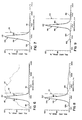
- the graph of Fig. 6 shows the relative spectral irradiance profile 80, over the 400-2500 nanometer spectral range, of a second ytterbia mantle in accordance with the invention.
- That mantle is formed of a similar tube of knit rayon that was imbibed, in a 1.2 molar ytterbium nitrate solution and processed by uniformly torching the dried nitrate impregnated rayon mantle with a blue propane flame to pyrolyze the rayon and shrink the mantle skirt onto its support tube.
- That ytterbia mantle-support tube assembly was energized with an air-isobutane flame (air/fuel ratio of 27:1) and its radiated flux was measured over the 400-2500 nanometer spectral range with the same equipment as described in connection with the mantle shown in Figs. 1 and 2.
- This ytterbia mantle had a radiation peak 82 at about 970 nanometers (the spectroradiometer being set to have a slit width of about 0.6 mm at that wavelength) with half peak intensity points 84, and 86 at about 875 and 1060 nanometers respectively so that peak 82 has a width at half maximum intensity of about 185 nanometers.
- Measured radiated flux levels of lower skirt 88 were less than one-half percent from 450 to 625 nanometers; and measured radiated flux levels of upper skirt 90 were two percent or less at wavelengths from 1300 to 2500 nanometers. Peak 82 is offset about 180 nanometers below silicon threshold 32. The silicon conversion efficiency of this ytterbia-isobutane mantle system was 74%.
- Curve 92 is the relative spectral irradiance profile of a commercial Coleman (Welsbach type) mantle energized in an air/propane flame. It will be seen that curve 92 has a broad spectral profile similar to curve 34, curve 92 having a radiated flux level at 650 nanometers (the upper end of the visible range) of about 46% of its peak radiated flux; radiated flux levels in the near infrared region of about 62% of peak at 800 nanometers, 71% of peak at 900 nanometers, and 85% of peak at 1000 nanometers; a peak radiated flux at about 1400 nanometers (the spectroradiometer being set to have a slit width of about 0.3 mm at that wavelength); and radiated flux outputs of about 80% of peak at 1800 nanometers, 52% of peak at 2100 nanometers and 42% of peak at 2400 nanometers. The silicon conversion efficiency of this Welsbach mantle-propane system is 23%.
- Another mantle in accordance with the invention is a self-supporting ytterbia fiber fabric structure that defines a hollow chamber of about twelve millimeters in diameter with its tip about 2.5 centimeters above the upper end surface of a brass fuel supply support tube to which it is secured, the support tube having an outer diameter of about twelve millimeters and an inner diameter of about seven millimeters, the lower portion of the mantle fabric sleeve being firmly shrink-secured to the outer surface of the support tube.
- the mantle fabric is composed of ytterbia multi-filament strands in a knit array that has an open area of about 30%, the cross-sectional dimensions of the individual ytterbia fibers of the strands of this mantle being about fifteen micrometers, and the strands having cross-sectional dimensions of about 0.2 millimeter with openings having dimensions of about 0.3 millimeter.
- This mantle was manufactured from continuous low twist, low tenacity (highly reticulated), viscose rayon yarn (300 denier/50 filament) that was knitted into a continuous tubular sleeve using a Lamb circular string knitter (Model ST3A/ZA) with a 3.8 centimeter diameter arbor and sixty needle capacity using sixty equally spaced needles in the arbor with tension on both the yarn and the knitted sleeve to attain eight stitches per linear centimeter of tensioned sleeve.
- a Lamb circular string knitter Model ST3A/ZA
- An imbibing solution 1.57 molar in ytterbium nitrate was formed and a length of the knitted rayon sleeve was immersed for about one hour in the imbibing solution at room temperature, with gentle agitation to promote penetration of the imbibing solution into the rayon fibers.
- the imbibed sleeve was formed into mantle socks, disposed on brass support tubes, and processed by uniformly torching the dried nitrate impregnated rayon mantle with a blue propane flame to pyrolyze the rayon and shrink the mantle skirt onto its brass support tube.
- That ytterbia mantle-support tube assembly was then exposed to an air-isobutane flame (91 sccm isobutane, 2460 sccm air as measured with Tylan controllers - an oxidant fuel ratio of about 27:1), and its resulting spectral irradiance profile was measured with a Beckman DK-2A prism spectroradiometer operated in single-beam mode with the spectroradiometer set to have a slit width of about 0.035 mm over the 400-2400 nanometer wavelength range.
- the resulting radiated flux profile of that ytterbia mantle had a radiation peak at about 1010 nanometers (offset about 140 nanometers below the silicon threshold) with half intensity points at about 905 nanometers and 1080 nanometers respectively so that its peak had a full width at half maximum of about 175 nanometers.
- the lower skirt of the profile of the mantle had measured radiated flux levels of less than one-half percent of the peak, and the upper skirt of the profile had radiated flux levels of seven percent or less at spectral wavelengths from 1300 nanometers to 2400 nanometers.
- the silicon conversion efficiency of this ytterbia-isobutane mantle system was about 72%.
- the relative spectral irradiance profile 100 of still another ytterbia mantle is shown in Fig. 7.
- the ytterbia fiber configuration and composition (a 1.74 molar ytterbia imbibing solution was used) were similar to mantle 10.
- profile 100 was obtained by exposing the mantle to an air-hydrogen flame (maximum flame temperature about 2045°C) with the burner stem orifice reduced to an inner diameter of 0.25 millimeter to avoid flashback at the fuel flow rate employed (a 1.52 millimeter burner orifice was used with isobutane fuels).
- the ytterbia mantle was exposed to a air-hydrogen flame (70 sccm air flow rate, 112 sccm hydrogen flow rate) and measured with the Beckman spectroradiometer operated in single beam mode with a 0.8 millimeter slit width at the 965 nanometer peak.
- the resulting normalized spectral irradiance profile 100 as shown in Fig.
- Profile 120 of that ytterbia-ceria mantle had a radiation peak 122 at about 960 nanometers (the spectroradiometer being set to have a slit width of about 0.6 mm at that wavelength), half intensity points 124, 126 at about 900 and 1050 nanometers respectively so that peak 122 has a full width at half maximum of about 150 nanometers; a lower skirt 128 of less than one-half percent measured radiated flux levels from 450 to 525 nanometers; about one percent of peak radiated flux at 650 nanometers; and an upper skirt 130 with radiated flux levels of six to eight percent from 1300 nanometers to 1900 nanometers and radiated flux levels of three percent or less from 2200 nanometers to 2500 nanometers.
- Mantle profile 120 has a silicon conversion efficiency of 58%.
- Fig. 9 Shown in Fig. 9 is the normalized relative spectral irradiance profile 140, over a 450-2500 nanometer spectral range, of an erbia mantle formed by imbibing a rayon sleeve similar to the sleeve used to form mantle 10 with a 0.92 molar solution of erbium nitrate and then carefully torching the imbibed sleeve in propane to pyrolyze the rayon and shrink the mantle skirt on its support tube.
- Profile 140 was obtained by exposing that erbia mantle, to a air-isobutane flame (air/fuel ratio of 26.2). The resulting erbia mantle profile 140 as shown in Fig.
- the emissivity of the erbia mantle material is about 0.5
- the actual temperature of the erbia mantle is about 1600°C.
- This narrow band erbia radiation source couples well to a germanium photocell and such a thermophotovoltaic system has a germanium photocell conversion efficiency of about 77%.
- the erbia mantle provides a high output at about 1.5 microns, the wavelength of interest, in contrast to the lower absolute values of output peaks of comparable broad band radiators of the type indicated by curve 34, for example.
Landscapes
- Engineering & Computer Science (AREA)
- General Engineering & Computer Science (AREA)
- Luminescent Compositions (AREA)
- Resistance Heating (AREA)
Description
- This invention relates to a thermophotovoltaic device containing a radiation source and more particularly a source of the thermally excited type in which radiation is emitted from a heated element.
- Radiation sources of the thermally excited type such as incandescent lamps in which light is emitted from a highly heated resistance wire and incandescent mantles of the Welsbach type have long been known. Such radiation sources generally have characteristics of the "black body", or more realistically "gray body", type and emit radiation over a broad spectral band.
- Radiation that is absorbed by a photovoltaic cell in the neighborhood of a potential barrier, usually a pn junction, gives rise to separated electron-hole pairs which create an electric potential. The photocell conversion efficiency is a function of the band gap (in electron volts) and the temperature of the particular photocell material. Among the known types of photocell material are silicon, which has a band gap of about 1.1 electron volts, equivalent to a wavelength of about 1150 nanometers; and germanium, which has a band gap of about 0.7 electron volt, equivalent to a wavelength of about 1800 nanometers. In a thermophotovoltaic device, a close match between the spectrum of photon energy radiated from the radiation source and the electron production threshold of the photovoltaic cell results in a greater amount of energy which is absorbed by the photovoltaic cell boning converted to electrical energy and a minimal amount being converted to heat. Silicon photovoltaic cells have relatively low conversion efficiency in direct sunlight, in part because the specific spectral energy of solar radiation does not provide a good spectral match with the response of a silicon photovoltaic cell as that portion of solar radiation with wavelengths longer than 1100 nanometers is useless to the silicon cell photovoltaic conversion process and generates heat in the cell requiring an increased effort for cooling to keep the cell at its best performance, and as the maximum spectral radiance in sunlight occurs at about 500 nanometers which corresponds to a photon energy of 2.5 electron volts, while only 1.1 electron volts are required to produce the hole-electron pairs in silicon which contribute to external current flow and power output. The surplus energy of photons in the spectral region below 1100 nanometers is also converted to heat in the cell. While Welsbach mantles have been proposed for use in thermophotovoltaic energy conversion systems, such uses are not particularly efficient as such mantles generate substantial amounts of radiation throughout a spectral region that extends from the visible well into the infrared. Other proposed thermophotovoltaic energy conversions systems have used reflector and rare earth active filter arrangements (see e.g. US-A-3 751 303, US-A-3 929 510).
- It is the object of the invention to provide a thermophotovoltaic device with a narrow band thermal emitter.
- This object is solved with a thermophotovoltaic device as featured in claim 1 and in particular containing
a thermally excited radiation source with a narrow peak in the spectral profile of its radiated flux and skirt portions of the radiated flux profile on either side of the narrow peak being suppressed so that the emitted radiation has a concentrated spectral distribution. - According to the invention, the rare earth oxide radiator member of the narrow band thermally energized radiation source has a cross-sectional dimension in the range of five to thirty micrometers, and that rare earth oxide radiator member, when heated to about 1700°C, has a concentrated radiated flux over the 400-2500 nanometer wavelength range such that at least 50% of the radiated flux is within a spectral band that is less than 400 nanometers wide. The radiation source may be thermally excited by various techniques including, for example, electrical energy or liquid or gaseous fuels such as hydrogen, natural gas, propane, butane, isobutane or gasoline.
- In preferred embodiments, the narrow band thermally excited radiation source is composed of interlocked fibers of at least one oxide of a host rare earth metal selected from a class consisting of erbium, holmium, neodymium and ytterbium, the radiated flux of the radiation source having a full width at half maximum (at 1/2 the maximum radiated flux of the source) of less than 400 nanometers. The relative spectral irradiance profiles of preferred radiators also have suppressed skirt characteristics such that at
wavelengths 500 nanometers above and below the peak wavelength, the skirts have radiated fluxes that are less than ten and more preferably less than five percent of the profile peak radiated flux. In particular embodiments, the radiation source is a self-supporting rare earth oxide fiber mantle that defines a hollow space, and that is secured on a support tube by an integral shrunken skirt portion. - In accordance with the invention there is provided a thermophotovoltaic device that includes a photocell and a radiator of rare earth metal oxide material disposed in optically coupled relation to the photocell. Such thermophotovoltaic devices may be used in power generation, topping cycles, cogeneration, or communication applications, for example. The radiator and photocell may be close coupled, for example in the same housing, or spaced apart with the radiation from the radiator focused on the more remotely located photocell, or coupled as by means of fiber optic technology. The thermophotovoltaic device also includes means for thermally exciting the radiator to cause it to emit radiation in a spectral irradiance profile that has a radiated flux peak with a full width at half maximum of less than 400 nanometers, the radiated flux peak being less than 400 nanometers below (on the higher energy side of) the electron production threshold of the photocell. The photon conversion efficiency of preferred thermophotovoltaic devices is more than fifty percent.
- In accordance with an embodiment of the invention a radiator of rare earth metal oxide material is thermally excited at a temperature in the range of 1500 - 2000°C to cause the radiator to emit radiation in a spectral irradiance profile that has a narrow radiated flux peak that has a full width at half maximum of less than 400 nanometers and preferably less than 200 nanometers, and suppressed skirt characteristics such that at wavelengths in the range of 300 - 500 nanometers above and below the flux peak, the radiated flux levels of the skirts are less than ten and preferably less than five percent of the peak radiated flux.
- In particular thermophotovoltaic device embodiments, the thermal excitation system includes a liquid hydrocarbon fuel supply, a conduit connected to the fuel supply that has an outlet port aligned with the rare earth metal oxide radiator, a fuel control for controlling the flow of fuel through the conduit to the radiator, and an igniter mechanism for igniting the fuel. Particular radiators are self-supporting rare earth metal oxide fiber mantles that are composed of metal oxide multi-filament strands with cross-sectional strand dimensions in the range of 0.05 - 0.3 millimeter and filament cross-sectional dimensions in the range of five to thirty micrometers. A reflector system may advantageously be employed for collecting, directing and concentrating the radiated flux from the mantle to the photocell, and radiation transmitting thermal isolation structure may be positioned between the mantle (or mantles) of the radiation source and the photovoltaic cell array. Particularly useful thermophotovoltaic devices include an ytterbia mantle coupled to a silicon type photocell and an erbia mantle coupled to a germanium type photocell.
- Mantle arrangements such as multiple mantles or mantles of more complex geometry such as pleated structures that are designed to radiate more energy without a corresponding increase in convection loss may also be employed in thermophotovoltaic devices in accordance with the invention. Additional efficiency enhancement may be obtained by a regenerator through which the hot convection gas is routed to warm the incoming combustion air. Incandescent mantles as used in the present invention are described in EP-A-0101086 which belongs to the state of the art according to Art 54(3)EPC.
- Other features and advantages of the invention will be seen as the following description of particular embodiments of the invention progresses, in conjunction with the drawings, in which:
- Fig. 1 is an enlarged view of a mantle type radiation source and its support in accordance with aspects of the invention;
- Fig. 2 is a magnified view of a portion of the rare earth oxide fabric of the mantle shown in Fig. 1;
- Fig. 3 is a graph indicating spectral characteristics of an ytterbia mantle type radiation source in accordance with the invention, and of a predominately thoria mantle type radiation source of similar configuration;
- Fig. 4 is a diagram of a thermophotovoltaic device in accordance with aspects of the invention;
- Fig. 5 is a diagrammatic front view of the photocell array employed in the thermophotovoltaic device shown in Fig. 4;
- Fig. 6 is a graph indicating spectral characteristics of another ytterbia radiation source in accordance with aspects of the invention and spectral characteristics of a commercially available predominately thoria mantle;
- Fig. 7 is a graph indicating spectral characteristics of another ytterbia radiation source in accordance with the invention energized with a hydrogen flame;
- Fig. 8 is a graph indicating spectral characteristics of an ytterbia-ceria radiation source; and
- Fig. 9 is a graph indicating spectral characteristics of an erbia radiation source in accordance with aspects of the invention.
- The diagrammatic view of Fig. 1 shows a
radiation source 10 of the mantle type that is mounted onsupport tube 12 of mullite or other suitable heat resistant material.Support tube 12 has an outer diameter of about five millimeters and an inner diameter of about three millimeters. Mantle 10 is a self-supporting ytterbia fiber fabric structure that defines a hollow chamber 14 of about seventy cubic millimeters volume withtip 16 about 1/2 centimeter above theupper end surface 18 ofsupport tube 12. Thelower portion 20 of the mantle fabric is about 1/2 centimeter in length and is firmly shrink-secured to the outer surface ofsupport tube 12. The mantle fabric is formed of ytterbiamulti-filament strands 22 in an open knit array withopenings 24 such that the open area of the fabric is about 60%. The cross-sectional dimensions of the individual ytterbia filaments 26 (Fig. 2) ofstrands 22 are in the range of about five-ten micrometers, and thestrands 22 have cross-sectional dimensions in the order of about 0.1 millimeter withopenings 24 having dimensions of about 0.5 millimeter. - A process for manufacturing
mantle 10 is as follows. Continuous low twist, low tenacity (highly reticulated), viscose rayon yarn (150 denier/60 filament) is knitted into a continuous tubular sleeve using a Lamb circular string knitter (Model ST3A/ZA) with a 2.2 centimeter diameter arbor and 24 needle capacity using 12 equally spaced needles in the arbor. The yarn is knitted into a continuous tubular sleeve with tension on both the yarn and the knitted sleeve to attain about three stitches per linear centimeter of tensioned sleeve, and the continuous length of knitted sleeve is wound onto a take-up spool. - An imbibing solution is formed by dissolving hydrated ytterbium nitrate (Yb(NO₃)₃.4 H₂O) (reagent grade) in distilled water (together with a small amount of a non-ionic wetting agent such as Triton X-100) to provide a solution 1.75 molar in ytterbium nitrate.
- A knitted rayon sleeve unit, about thirty centimeters long, is immersed for about ten minutes in the imbibing solution at room temperature, with gentle agitation to promote penetration of the imbibing solution into the rayon fibers. After the ten minute imbibition, the sleeve is removed from the solution, squeeze dried and then transferred to a plastic centrifuge tube. The sleeve is then centrifuged for ten minutes at about 200g's to remove surface liquid. It is convenient to secure a metal screen halfway from the bottom of the centrifuge tube so that liquid does not rewet the surface of the sleeve during or after centrifugation.
- After centrifugation, the imbibed sleeve is formed into mantle socks with aid of a Teflon sock-shaping rod that is fourteen millimeters in diameter and has a hemispherical end. A seven centimeter length of imbibed sleeve is slipped over the shaping rod, and tied off at the hemispherical end of the shaping rod with a piece of treated yarn unraveled from the bottom of the knit sleeve. The shaped sock is then dried with a flow of hot (about 90°C) air, slipped off the shaping rod, cut to about 3.6 centimeters length, and then hung on a fixture that includes a series of upstanding mullite posts (spaced at about three centimeter intervals) on a mullite base. Each post has a diameter of about three millimeters and a length of about 3.7 centimeter and receives a
support tube 12 and spacer, the top oftube 12 being spaced about five millimeters below the top of the post so that the top of the shaped sock is supported on the mullite post and the lower portion of the shaped sock extends over thesupport tube 12. Optionally a ring of sodium silicate that has been pretreated byheating tube 12 to about 900°C may be carried bytube 12. - The fixture with knitted imbibed socks hung over the
support sleeves 12 on the fixture posts is then subjected to a firing procedure to convert the ytterbium nitrate imbibed cellulosic mantle socks into densified ytterbia mantles. - In the firing sequence, the fixture with imbibed socks is placed in a tubular oven that is about 1.2 meters in length and about five centimeters in inner diameter. At ambient temperature (about 25°C), the oven is flushed with tank nitrogen at a flow rate of 200 cubic centimeters per minute (a flow velocity of about ten centimeters per minute), and with this inert atmosphere in the oven, the oven temperature is increased at a rate of 400°C per hour. The mantle fabric undergoes denitration at about 160°C. At this point the fabric color changes rapidly from white to golden tan. Immediately after this color change, oxygen is added to the nitrogen flow at a rate of about five cubic centimeters per minute. Heating continues at the same rate to a temperature of about 320°C. During this time the color continuously changes from golden tan to dark brown or black with modest shrinkage (about 10%) of the fabric, which indicates partial decomposition of the organic material. The oven temperature is then held at about 320°C for about one and one-half hours and the mantle color turns from black to light gray or white. During this soaking interval, the remaining carbon is oxidized and driven off and the mantle shrinks to about 1/3 its original dimensions with its
lower portion 20 shrunk ontotube 12 essentially as shown in Fig. 1. At the end of the soaking interval, the flow of oxygen is increased to fifty cubic centimeters per minute (a gas mixture of 20% oxygen) and the oven temperature is increased over a twenty-four minute interval to a temperature of 900°C. The heater is then turned off and the oven is rapidly cooled to ambient temperature. After cooling, each mantle subassembly is removed from its storage holder post and is exposed to a burning mixture of isobutane and air (at an estimated mantle temperature of about 1700°C) for five minutes to further shrink and densify the ytterbia fabric. - The resulting ytterbia fabric, in visual appearance, substantially retains characteristic physical textile attributes of its precursor rayon fabric, although it is substantially reduced in dimension. This ytterbia fabric has relatively high density, is flexible, and has a minimal defect (flaws) microstructure, a concentrated radiated flux profile and, in the described mantle configuration, withstands impact loads of two thousand g's.
- The graph of Fig. 3 shows a relative
spectral irradiance profile 30 ofmantle 10, over a 400 - 2500 nanometer spectral range when that mantle is exposed to an air-isobutane flame (7 sccm isobutane, 113.6 sccm air as measured with Tylan controllers - an oxidant fuel ratio of 16.2).Profile 30 was measured over an interval of 3.2 hours with a Beckman DK-2A prism spectroradiometer operated in single-beam mode with an adjustable slit width. Theoretical photovoltaic response of silicon is indicated bycurve 32 in Fig. 3; and the relative spectral irradiance profile of a predominantly thoria mantle, of similar physical shape tomantle 10 that was thermally energized with an an air-isobutane flame (7 sccm isobutane, 191.7 sccm air - an oxidant-fuel ratio of 27.4) and measured in the same manner and over the same wavelength range asprofile 30, is indicated by curve 34. - The radiated
flux profile 30 ofytterbia mantle 10 has aradiation peak 36 at about 985 nanometers (the spectroradiometer being set to have a slit width of about 0.6 mm at that wavelength) with half intensity points 38, 40 at about 890 nanometers and 1050 nanometers respectively so thatpeak 36 has a full width at half maximum of about 160 nanometers. Thelower skirt 42 ofprofile 30 ofmantle 10 has measured radiated flux levels of less than one-half percent of the peak from 400 nanometers to 725 nanometers, and theupper skirt 44 ofprofile 30 has radiated flux levels of one percent or less at spectral wavelengths from 1300 nanometers to 2500 nanometers. - In contrast, the Welsbach type thoria mantle of similar physical size and construction has a broad band spectral profile as indicated by curve 34, that profile indicating a radiated flux at 650 nanometers (in the visible region) that is about ten percent of the peak radiated flux; radiated fluxes of about 35% of peak at 800 nanometers, 51% of peak at 900 nanometers, 62% of peak at 1000 nanometers, 81% of peak at 1100 nanometers in the near infrared region; a peak radiated flux at about 1400 nanometers in the far infrared region (the spectroradiometer being set to have a slit width of about 0.8 mm at that wavelength); and radiated flux intensities of about 87% at 1800 nanometers, 64% at 2100 nanometers and 50% at 2400 nanometers. It will be seen that the
ytterbia mantle 10 has a narrow well-definedradiation peak 36 in contrast with the broad and diffuse radiation profile 34 of the Welsbach type mantle, as well as almost total suppression ofskirts peak 36. The amplitude ofpeak 36, in absolute terms, is substantially greater than (about twice) the peak value of the broad band radiator (curve 34) (the area undercurve 30 being about one-third the area under curve 34 over the 500 - 2500 nanometer range). Theytterbia mantle 10 thus provides a high output at about one micron, the wavelength of interest. - The thermophotovoltaic system shown in Fig. 4 incorporates
ytterbia mantle 10.Support tube 12 is connected via a fuel delivery system to fuelreservoir 50 that contains isobutane fuel withoutlet tube 52 extending to pressure regulator 54. The high velocity jet at flow-through outlet orifice 56 (0.05 millimeter diameter) is directed through venturi 58 (a throat diameter of about one millimeter) to aspirate and mix air with the isobutane fuel for flow throughsupport tube 12 tomantle 10. Piezoelectric ignitor 60 or other suitable ignition means is utilized to generate a spark after the air/fuel mixture delivery system is turned on to ignite the air isobutane fuel mixture at the mantle and provide a maximum flame temperature of about 1900°C. -
Mantle 10 is disposed in a polished and passivatedaluminum reflector 62 which collects and collimates the radiation emitted bymantle 10. Atubular reflector array 64 directs the radiation frommantle 10 on siliconphotovoltaic cell array 70 that is mounted onheat sink structure 72.Reflector array 64 is composed of a series of spaced, overlappingwall sections 66 withventilation ports 68. Radiation transmittingthermal isolation window 74 of glass or other suitable material is supported on one of thesections 66 and disposed betweenmantle 10 andphotocell array 70 for isolating the hot combustion gas in the mantle compartment from thephotovoltaic cell array 70. The surfaces ofwindow 74 preferably carry an anti-reflecting coating to lower reflection losses. Preferably, the front surfaces of the photodiodes 76 (Fig. 5) also carry an anti-reflection coating for the same reason thatwindow 74 is coated. To maximize photon conversion,silicon photodiodes 76 preferably are about one millimeter in thickness. Provision of a reflecting layer (for example of silver, aluminum or copper) on the back contacts of thephotodiodes 76 further enhances probability of photon conversion.Control system 78 may be connected between regulator 54 anddiode array 70 for monitoring the output voltage and modulating the fuel flow by control of regulator 54 to control the electrical output of thephotodiode array 70. - The optical temperature of ytterbia mantles 10, measured with a Leeds & Northrup optical pyrometer (Catalog # 8632-C) is in the range of 1160-1190°C. As the emissivity of the highly reflective mantle material (at the 660 nm optical pyrometer measuring wavelength) is less than 0.1, the actual temperature of
mantle 10 is about 1700°C. - The electron production threshold of the silicon
photovoltaic cells 76 is 1150 nanometers, as indicated bycurve 32 in Fig. 3. Theytterbia mantle 10, when heated as described above to about 1700°C, has itspeak 36 in close proximity to (about 165 nanometers from) siliconelectron production threshold 32 such that the electrical energy conversion efficiency of the system is high - 80% of the total radiated flux output ofmantle 10 over the 400-2500 nanometer wavelength range being convertible into electrical energy on the basis of the theoretical silicon cell response indicated in Fig. 3. - The graph of Fig. 6 shows the relative
spectral irradiance profile 80, over the 400-2500 nanometer spectral range, of a second ytterbia mantle in accordance with the invention. That mantle is formed of a similar tube of knit rayon that was imbibed, in a 1.2 molar ytterbium nitrate solution and processed by uniformly torching the dried nitrate impregnated rayon mantle with a blue propane flame to pyrolyze the rayon and shrink the mantle skirt onto its support tube. That ytterbia mantle-support tube assembly was energized with an air-isobutane flame (air/fuel ratio of 27:1) and its radiated flux was measured over the 400-2500 nanometer spectral range with the same equipment as described in connection with the mantle shown in Figs. 1 and 2. This ytterbia mantle had aradiation peak 82 at about 970 nanometers (the spectroradiometer being set to have a slit width of about 0.6 mm at that wavelength) with half peak intensity points 84, and 86 at about 875 and 1060 nanometers respectively so thatpeak 82 has a width at half maximum intensity of about 185 nanometers. Measured radiated flux levels oflower skirt 88 were less than one-half percent from 450 to 625 nanometers; and measured radiated flux levels ofupper skirt 90 were two percent or less at wavelengths from 1300 to 2500 nanometers.Peak 82 is offset about 180 nanometers belowsilicon threshold 32. The silicon conversion efficiency of this ytterbia-isobutane mantle system was 74%. -
Curve 92 is the relative spectral irradiance profile of a commercial Coleman (Welsbach type) mantle energized in an air/propane flame. It will be seen thatcurve 92 has a broad spectral profile similar to curve 34,curve 92 having a radiated flux level at 650 nanometers (the upper end of the visible range) of about 46% of its peak radiated flux; radiated flux levels in the near infrared region of about 62% of peak at 800 nanometers, 71% of peak at 900 nanometers, and 85% of peak at 1000 nanometers; a peak radiated flux at about 1400 nanometers (the spectroradiometer being set to have a slit width of about 0.3 mm at that wavelength); and radiated flux outputs of about 80% of peak at 1800 nanometers, 52% of peak at 2100 nanometers and 42% of peak at 2400 nanometers. The silicon conversion efficiency of this Welsbach mantle-propane system is 23%. - Another mantle in accordance with the invention is a self-supporting ytterbia fiber fabric structure that defines a hollow chamber of about twelve millimeters in diameter with its tip about 2.5 centimeters above the upper end surface of a brass fuel supply support tube to which it is secured, the support tube having an outer diameter of about twelve millimeters and an inner diameter of about seven millimeters, the lower portion of the mantle fabric sleeve being firmly shrink-secured to the outer surface of the support tube. The mantle fabric is composed of ytterbia multi-filament strands in a knit array that has an open area of about 30%, the cross-sectional dimensions of the individual ytterbia fibers of the strands of this mantle being about fifteen micrometers, and the strands having cross-sectional dimensions of about 0.2 millimeter with openings having dimensions of about 0.3 millimeter.
- This mantle was manufactured from continuous low twist, low tenacity (highly reticulated), viscose rayon yarn (300 denier/50 filament) that was knitted into a continuous tubular sleeve using a Lamb circular string knitter (Model ST3A/ZA) with a 3.8 centimeter diameter arbor and sixty needle capacity using sixty equally spaced needles in the arbor with tension on both the yarn and the knitted sleeve to attain eight stitches per linear centimeter of tensioned sleeve. An imbibing solution 1.57 molar in ytterbium nitrate was formed and a length of the knitted rayon sleeve was immersed for about one hour in the imbibing solution at room temperature, with gentle agitation to promote penetration of the imbibing solution into the rayon fibers. After imbibition and centrifugation, the imbibed sleeve was formed into mantle socks, disposed on brass support tubes, and processed by uniformly torching the dried nitrate impregnated rayon mantle with a blue propane flame to pyrolyze the rayon and shrink the mantle skirt onto its brass support tube.
- That ytterbia mantle-support tube assembly was then exposed to an air-isobutane flame (91 sccm isobutane, 2460 sccm air as measured with Tylan controllers - an oxidant fuel ratio of about 27:1), and its resulting spectral irradiance profile was measured with a Beckman DK-2A prism spectroradiometer operated in single-beam mode with the spectroradiometer set to have a slit width of about 0.035 mm over the 400-2400 nanometer wavelength range. The resulting radiated flux profile of that ytterbia mantle had a radiation peak at about 1010 nanometers (offset about 140 nanometers below the silicon threshold) with half intensity points at about 905 nanometers and 1080 nanometers respectively so that its peak had a full width at half maximum of about 175 nanometers. The lower skirt of the profile of the mantle had measured radiated flux levels of less than one-half percent of the peak, and the upper skirt of the profile had radiated flux levels of seven percent or less at spectral wavelengths from 1300 nanometers to 2400 nanometers. The silicon conversion efficiency of this ytterbia-isobutane mantle system was about 72%. The relative
spectral irradiance profile 100 of still another ytterbia mantle is shown in Fig. 7. The ytterbia fiber configuration and composition (a 1.74 molar ytterbia imbibing solution was used) were similar tomantle 10. After the ytterbia mantle was carefully burned off in propane,profile 100 was obtained by exposing the mantle to an air-hydrogen flame (maximum flame temperature about 2045°C) with the burner stem orifice reduced to an inner diameter of 0.25 millimeter to avoid flashback at the fuel flow rate employed (a 1.52 millimeter burner orifice was used with isobutane fuels). The ytterbia mantle was exposed to a air-hydrogen flame (70 sccm air flow rate, 112 sccm hydrogen flow rate) and measured with the Beckman spectroradiometer operated in single beam mode with a 0.8 millimeter slit width at the 965 nanometer peak. The resulting normalizedspectral irradiance profile 100 as shown in Fig. 7 had a peak 102 at about 965 nanometers (offset about 185 nanometers from silicon threshold 32), half intensity points 104, 106 at about 890 and 1050 nanometers so thatpeak 102 had a full width at half maximum of about 160 nanometers; alower skirt 108 that had less than one-half percent measured radiated flux levels from 450 to 675 nanometers and an upper skirt 110 that had radiated flux levels of about one percent from 1500 to 2300 nanometers (with the exception of a two percent radiated flux level at 1900 nanometers). The silicon conversion efficiency of this ytterbia-hydrogen mantle system was 76%. The relative spectral irradiance profile of still another mantle system is shown in Fig. 8, a knitted rayon tube of the same configuration as that used formantle 10 being imbibed with a solution of 1.69 molar ytterbia nitrate and 0.035 molar cerium nitrate and then pyrolyzed by burning off in propane. Its radiated flux was then measured with the Beckman spectroradiometer with the same techniques as employed with the preceding examples employing a slit width of 0.55 millimeter at the 960 nanometer peak.Profile 120 of that ytterbia-ceria mantle had aradiation peak 122 at about 960 nanometers (the spectroradiometer being set to have a slit width of about 0.6 mm at that wavelength), half intensity points 124, 126 at about 900 and 1050 nanometers respectively so thatpeak 122 has a full width at half maximum of about 150 nanometers; alower skirt 128 of less than one-half percent measured radiated flux levels from 450 to 525 nanometers; about one percent of peak radiated flux at 650 nanometers; and anupper skirt 130 with radiated flux levels of six to eight percent from 1300 nanometers to 1900 nanometers and radiated flux levels of three percent or less from 2200 nanometers to 2500 nanometers.Mantle profile 120 has a silicon conversion efficiency of 58%. - Shown in Fig. 9 is the normalized relative
spectral irradiance profile 140, over a 450-2500 nanometer spectral range, of an erbia mantle formed by imbibing a rayon sleeve similar to the sleeve used to formmantle 10 with a 0.92 molar solution of erbium nitrate and then carefully torching the imbibed sleeve in propane to pyrolyze the rayon and shrink the mantle skirt on its support tube.Profile 140 was obtained by exposing that erbia mantle, to a air-isobutane flame (air/fuel ratio of 26.2). The resultingerbia mantle profile 140 as shown in Fig. 9 had aradiation peak 142 at about 1500 nanometers (the spectroradiometer being set to have a slit width of about 0.4 mm at that wavelength) -peak 142 being offset about, 300 nanometers from germaniumelectron production threshold 144; half intensity points 146 and 148 at about 1430 and 1570 nanometers respectively so thatpeak 142 had a full width at half maximum of about 140 nanometers; alower skirt 150 that had less than one percent of peak radiated flux for the range of 450-750 nanometers, and acomponent 152 at about three percent of peak intensity from 900 nanometers to 1000 nanometers; and anupper skirt 154 that had radiated flux levels of two percent or less from 1800 nanometers to 2500 nanometers. In a more precise measurement ofprofile 140 over the 1200 - 2000 nanometer wavelength range (the spectroradiometer being set to have a slit width of about 0.04 mm) -peak 142 was located at about 1515 nanometers (offset about 285 nanometers from germaniumelectron production threshold 144; and half intensity points 146 and 148 were at about 1480 and 1545 nanometers respectively so thatpeak 142 had a full width at half maximum of about 65 nanometers. The optical temperature of erbia mantles, measured with a Leeds & Northrup optical pyrometer (Model #8632-C) is in the range of 1400-1450°C. As the emissivity of the erbia mantle material (at the 660 nm optical pyrometer measuring wavelength) is about 0.5, the actual temperature of the erbia mantle is about 1600°C. This narrow band erbia radiation source couples well to a germanium photocell and such a thermophotovoltaic system has a germanium photocell conversion efficiency of about 77%. The erbia mantle provides a high output at about 1.5 microns, the wavelength of interest, in contrast to the lower absolute values of output peaks of comparable broad band radiators of the type indicated by curve 34, for example.
Claims (18)
- A thermophotovoltaic device comprising a photocell (70), a rare earth metal oxide radiator being a mantle (10) composed of metal oxide filaments, each said filament having a cross-sectional dimension in the range of 5 to 30 µm and including at least one oxide of a metal selected from the class consisting of erbium, holmium, neodynium and ytterbium, and disposed in optically coupled relation to said photocell, and means for thermally exciting said radiator to cause it to emit radiation , said radiator (10), when heated to 1700° C, emitting radiation in a spectral irradiance profile that has a narrow radiated flux peak that is located less than 400 nm below the electron production threshold of said photocell, said flux peak having a full width at half maximum of less than 400 nm and said relative spectral irradiance profile of said radiator also having suppressed skirt characteristics such that, at wavelengths 500 nm above and below said flux peak, the radiated flux levels of said skirts are less than 10 % of the radiated flux at said peak.
- The thermophotovoltaic device of claim 1 further characterized in that said device has a photon conversion efficiency of more than 50 %.
- The thermophotovoltaic device of either claim 1 or 2 further characterized in that said mantle is formed of multi-filament metal oxide strands having a cross-sectional dimension in the range of 0.05 - 0.3 millimeter.
- The thermophotovoltaic device of claim 1 further characterized in that said mantle (10) has an overall length in the range of about 0.5 - 4.0 cm and a diameter in the range of about 0.5 - 2.0 centimeters.
- The thermophotovoltaic device of claim 4 further characterized in that said mantle (10) is shrink-supported on a fuel supply conduit (12).
- The thermophotovoltaic device of any claims 1 - 5 further characterized in that said radiator (10) is composed of filaments of an oxide of ytterbium, each said filament having a cross-sectional dimension in the order of 10 µm; and said photocell (70) is of the silicon type.
- The thermophotovoltaic device of any of claims 1 - 5 further characterized in that said radiator (10) is composed of filament of an oxide of erbium, each said filament having a cross-sectional dimension in the order of 10 µm, and said photocell (70) is of the germanium type.
- The thermophotovoltaic device of any of claims 1 - 7 further characterized by the provision of a reflector system (64) for collecting and directing the radiated flux from said radiator (10) to said photocell (70).
- The thermophotovoltaic device of any of claims 1 - 8 further characterized by the provision of radiation transmitting thermal isolation means (74) interposed between said radiator and said photocell.
- The thermophotovoltaic device of any of claims 1 - 9 further characterized in that said radiator, when heated to 1700° C, emits radiation in a concentrated portion of the 400 - 2500 nanometer wavelength range such that at least 50 % of the radiated flux is within a less than 400 nanometers in width, said flux peak has a full width at half maximum of less than 200 nm and said suppressed skirt characteristics are such that, at wavelenghts in the range of 300 nm to 500 nm above and below said flux peak, the radiated flux levels of the skirts are less than 5 % of the radiated flux at said peak.
- A thermophotovoltaic device according to claim 1 further comprising:
a fuel supply (50),
a fuel supply conduit (52) connected to said fuel supply and having an outlet port (56),
a metal oxide fiber mantle (10) supported on said fuel supply conduit (52) adjacent said outlet port (56), a fuel control (54) for controlling the flow of fuel to said mantle (10) through said conduit (52), and an igniter mechanism (60), for igniting said fuel to cause said mantle to emit the radiation, which has, when said mantle (10) is heated to about 1700° C, a concentrated radiated flux output over the 400 - 2500 nanometer wavelength range such that at least 50 % of said radiated flux is within a band less than 400 nanometers in width. - The thermophotovoltaic device of claim 11 further chacterized in that said fuel is a liquid or gaseous fuel such as hydrogen, natural gas, propane, butane, isobutane or gasoline.
- The thermophotovoltaic device of either claim 11 or 12 further characterized in that said mantle (10) is composed of interlocked metal oxide fibers, each said fiber having a cross-sectional dimension in the range of 5 to 30 µm.
- The thermophotovoltaic device of claim 13 further characterized in that said fibers of said mantle (10) are composed substantially entirely of the oxide of a host metal selected from the group of ytterbium and erbium.
- The thermophotovoltaic device of any of claims 11 - 14 and further characterized by the provision of a reflector system (64) for collecting and directing the radiated flux from said mantle (10) to said photovoltaic device.
- The thermophotovoltaic device of any of claims 11 - 15 and further characterized by the provision of radiation transmitting thermal isolation means (74) interposed between said mantle and said photovoltaic device.
- The thermophotovoltaic device of any of claims 11 - 16 further characterized in that said mantle (10), when heated to 1700° C, emits radiation in a spectral irradiance profile that has a narrow radiated flux peak that is located less than 400 nm below the electron production threshold of said photovoltaic device, said flux peak having a full width at half maximum of less than 400 nm and said relative spectral irradiance profile of said mantle also having suppressed skirt characteristics such that, at wavelengths 500 nm above and below said flux peak, the radiated flux levels of said skirts are less than 10 % of the radiated flux at said peak.
- The thermophotovoltaic device of claim 17 further characterized in that said mantle (10), when heated to 1700° C, emits radiation in a concentrated portion of the 400 - 2500 nm wavelength range such that at least 50 % of the radiated flux is within a band less than 400 nm in width, said flux peak has a full width at half maximum of less than 200 nm and said suppressed skirt characteristics are such that, at wavelengths in the range of 300 nm to 500 nm above and below said flux peak, the radiated flux levels of said skirts are less than five percent of the radiated flux at said peak.
Priority Applications (1)
| Application Number | Priority Date | Filing Date | Title |
|---|---|---|---|
| AT84306033T ATE104092T1 (en) | 1983-09-02 | 1984-09-03 | THERMOPHOTOVOLTAIC TECHNOLOGY. |
Applications Claiming Priority (4)
| Application Number | Priority Date | Filing Date | Title |
|---|---|---|---|
| US52901683A | 1983-09-02 | 1983-09-02 | |
| US529016 | 1983-09-02 | ||
| US634379 | 1984-07-31 | ||
| US06/634,379 US4584426A (en) | 1983-09-02 | 1984-07-31 | Thermophotovoltaic technology |
Publications (3)
| Publication Number | Publication Date |
|---|---|
| EP0139434A2 EP0139434A2 (en) | 1985-05-02 |
| EP0139434A3 EP0139434A3 (en) | 1987-11-11 |
| EP0139434B1 true EP0139434B1 (en) | 1994-04-06 |
Family
ID=27062911
Family Applications (1)
| Application Number | Title | Priority Date | Filing Date |
|---|---|---|---|
| EP84306033A Expired - Lifetime EP0139434B1 (en) | 1983-09-02 | 1984-09-03 | Thermophotovoltaic technology |
Country Status (7)
| Country | Link |
|---|---|
| US (1) | US4584426A (en) |
| EP (1) | EP0139434B1 (en) |
| BR (1) | BR8404360A (en) |
| CA (1) | CA1229496A (en) |
| DE (1) | DE3486294T2 (en) |
| ES (3) | ES8703006A1 (en) |
| MX (1) | MX161759A (en) |
Families Citing this family (45)
| Publication number | Priority date | Publication date | Assignee | Title |
|---|---|---|---|---|
| US5356487A (en) * | 1983-07-25 | 1994-10-18 | Quantum Group, Inc. | Thermally amplified and stimulated emission radiator fiber matrix burner |
| US4906178A (en) * | 1983-07-25 | 1990-03-06 | Quantum Group, Inc. | Self-powered gas appliance |
| JPS60501913A (en) * | 1983-07-25 | 1985-11-07 | クオンタム グル−プ インコ−ポレイテツド | Photoelectric control device |
| US4764104A (en) * | 1984-07-31 | 1988-08-16 | Tpv Energy Systems, Inc. | Narrow band thermal emitter |
| US4976606A (en) * | 1983-09-02 | 1990-12-11 | Tpv Energy Systems, Inc. | Thermophotovoltaic technology |
| US5057162A (en) * | 1983-09-02 | 1991-10-15 | Tpv Energy Systems, Inc. | Thermophotovoltaic technology |
| US4750943A (en) * | 1986-02-28 | 1988-06-14 | Tpv Energy Systems, Inc. | Thermophotovoltaic system |
| US4707560A (en) * | 1986-12-19 | 1987-11-17 | Tpv Energy Systems, Inc. | Thermophotovoltaic technology |
| DE3810617A1 (en) * | 1988-03-29 | 1989-10-19 | Bodenseewerk Geraetetech | METHOD FOR ORIENTING A TWO-AXIS PLATFORM |
| US4877553A (en) * | 1988-06-06 | 1989-10-31 | Tpv Energy Systems, Inc. | Gas mantle technology |
| US5080724A (en) * | 1990-03-30 | 1992-01-14 | The United States Of America As Represented By The Administrator Of The National Aeronautics And Space Administration | Selective emitters |
| US5278773A (en) * | 1990-09-10 | 1994-01-11 | Zond Systems Inc. | Control systems for controlling a wind turbine |
| US5092767A (en) * | 1990-10-18 | 1992-03-03 | Dehlsen James G P | Reversing linear flow TPV process and apparatus |
| US5044939A (en) * | 1990-10-18 | 1991-09-03 | Dehlsen James G P | Reversing linear flow TPV process and apparatus |
| US5137583A (en) * | 1991-04-17 | 1992-08-11 | White Consolidated Industries, Inc. | Emission technology |
| GR1000813B (en) * | 1991-06-07 | 1993-01-25 | Nikolaos Zeliotis | Pyrophotovoltaic system |
| US5503685A (en) * | 1993-07-02 | 1996-04-02 | Goldstein Mark K | Thermally stimulated focused photon sources |
| US5447786A (en) * | 1994-05-25 | 1995-09-05 | Auburn University | Selective infrared line emitters |
| US5512108A (en) * | 1994-09-29 | 1996-04-30 | R & D Technologies, Inc. | Thermophotovoltaic systems |
| US5593509A (en) * | 1995-03-17 | 1997-01-14 | Lockheed Idaho Technologies Company | Portable thermo-photovoltaic power source |
| US5597421A (en) * | 1995-11-14 | 1997-01-28 | Regan; Thomas | Reflector/collector for use in direct energy conversion systems |
| US5686368A (en) * | 1995-12-13 | 1997-11-11 | Quantum Group, Inc. | Fibrous metal oxide textiles for spectral emitters |
| US6104031A (en) * | 1997-02-24 | 2000-08-15 | Quantum Group, Inc. | Surveillance systems |
| US5932885A (en) * | 1997-05-19 | 1999-08-03 | Mcdermott Technology, Inc. | Thermophotovoltaic electric generator |
| US6092912A (en) * | 1998-10-16 | 2000-07-25 | Quantum Group, Inc. | Portable, small, light-weight radiant and/or electrical power generating sources |
| US6198760B1 (en) | 1999-05-27 | 2001-03-06 | The United States Of America As Represented By The Administrator Of The National Aeronautics And Space Administration | Selective emitter pumped rare earth laser |
| US6746149B1 (en) | 1999-06-01 | 2004-06-08 | The United States of America as represented by the Admistrator of NASA | Rare earth optical temperature sensor |
| US6176596B1 (en) | 1999-07-15 | 2001-01-23 | Thermo Power Corporation | Combination flashlight an electrical power source assembly and emitter and reflector therefor |
| US6372979B1 (en) * | 2000-06-30 | 2002-04-16 | Foy Streetman | Apparatus and method for converting artificially generated radiant energy to electrical energy |
| DE10114933B4 (en) * | 2001-03-26 | 2004-05-06 | Leonhard Bopp | Energy recovery device |
| DE10130010A1 (en) * | 2001-06-25 | 2003-01-02 | Georg Issakides | mantles |
| ITTO20020090A1 (en) * | 2002-02-01 | 2003-08-01 | C R F Societa Con Sortile Per | LIGHTING DEVICE. |
| US20050287042A1 (en) * | 2002-08-22 | 2005-12-29 | Chase George G | Nanofibers with modified optical properties |
| ITTO20021083A1 (en) * | 2002-12-13 | 2004-06-14 | Fiat Ricerche | MICROCOMBUSTOR SYSTEM FOR THE PRODUCTION OF ELECTRICITY. |
| DE10309561B4 (en) * | 2003-03-04 | 2006-01-05 | Heraeus Noblelight Gmbh | Electric heating element for an infrared radiator, infrared radiator and its use |
| WO2006017003A1 (en) * | 2004-07-07 | 2006-02-16 | Advanced Propulsion Technologies, Inc. | Radiant burner |
| US7863517B1 (en) * | 2005-08-30 | 2011-01-04 | Xtreme Energetics, Inc. | Electric power generator based on photon-phonon interactions in a photonic crystal |
| RU2344344C1 (en) * | 2007-05-21 | 2009-01-20 | Андрей Борисович Адамович | Method of biothermophotoelectrocatalytic convertion of energy released at enriched biogas fuel burning and device for its implementation |
| RU2362636C2 (en) * | 2007-10-12 | 2009-07-27 | Андрей Борисович Адамович | Biothermophotoelectrocatalytic cogeneration plant for ecologically safe utilisation of dumpsite biogas |
| RU2362637C2 (en) * | 2007-10-12 | 2009-07-27 | Андрей Борисович Адамович | Thermophotoelectrocatalytic cogeneration plant for utilising dumping site biogas |
| US10197711B2 (en) * | 2011-05-18 | 2019-02-05 | Ip Equity Management, Llc | Thin-film integrated spectrally-selective plasmonic absorber/ emitter for solar thermophotovoltaic applications |
| US9323299B2 (en) | 2012-08-27 | 2016-04-26 | Green Light Industries, Inc. | Multiple power source unit |
| SK289127B6 (en) * | 2018-10-17 | 2023-10-11 | Slovenská Technická Univerzita V Bratislave | Device for testing fire characteristics of electric cables |
| US20210257959A1 (en) * | 2020-02-18 | 2021-08-19 | Modern Electron, Inc. | Combined heating and power modules and devices |
| CN116045359A (en) * | 2023-01-09 | 2023-05-02 | 山西西电信息技术研究院有限公司 | A heating monitoring and management system based on the Internet of Things |
Family Cites Families (7)
| Publication number | Priority date | Publication date | Assignee | Title |
|---|---|---|---|---|
| US3331707A (en) * | 1963-07-31 | 1967-07-18 | Gen Motors Corp | Thermo-photovoltaic converter with radiant energy reflective means |
| US3433676A (en) * | 1964-10-21 | 1969-03-18 | Gen Motors Corp | Thermophotovoltaic energy convertor with photocell mount |
| US3751303A (en) * | 1971-06-03 | 1973-08-07 | Us Army | Energy conversion system |
| US3929510A (en) * | 1974-05-22 | 1975-12-30 | Us Army | Solar radiation conversion system |
| US4313024A (en) * | 1977-04-05 | 1982-01-26 | Horne William E | Conversion of solar to electrical energy |
| US4234352A (en) * | 1978-07-26 | 1980-11-18 | Electric Power Research Institute, Inc. | Thermophotovoltaic converter and cell for use therein |
| US4975044A (en) * | 1982-08-16 | 1990-12-04 | Tpv Energy Systems, Inc. | Gas mantle technology |
-
1984
- 1984-07-31 US US06/634,379 patent/US4584426A/en not_active Expired - Lifetime
- 1984-08-15 CA CA000461095A patent/CA1229496A/en not_active Expired
- 1984-08-29 MX MX202551A patent/MX161759A/en unknown
- 1984-08-31 ES ES535578A patent/ES8703006A1/en not_active Expired
- 1984-08-31 BR BR8404360A patent/BR8404360A/en unknown
- 1984-09-03 EP EP84306033A patent/EP0139434B1/en not_active Expired - Lifetime
- 1984-09-03 DE DE3486294T patent/DE3486294T2/en not_active Expired - Fee Related
-
1985
- 1985-10-31 ES ES548419A patent/ES8609867A1/en not_active Expired
-
1986
- 1986-07-01 ES ES556871A patent/ES8802201A1/en not_active Expired
Also Published As
| Publication number | Publication date |
|---|---|
| CA1229496A (en) | 1987-11-24 |
| ES8703006A1 (en) | 1987-01-16 |
| ES8609867A1 (en) | 1986-09-01 |
| US4584426A (en) | 1986-04-22 |
| MX161759A (en) | 1990-12-20 |
| ES8802201A1 (en) | 1988-04-01 |
| DE3486294T2 (en) | 1994-07-14 |
| DE3486294D1 (en) | 1994-05-11 |
| ES556871A0 (en) | 1988-04-01 |
| EP0139434A2 (en) | 1985-05-02 |
| BR8404360A (en) | 1985-07-30 |
| EP0139434A3 (en) | 1987-11-11 |
| ES535578A0 (en) | 1987-01-16 |
| ES548419A0 (en) | 1986-09-01 |
Similar Documents
| Publication | Publication Date | Title |
|---|---|---|
| US4584426A (en) | Thermophotovoltaic technology | |
| US4976606A (en) | Thermophotovoltaic technology | |
| US5057162A (en) | Thermophotovoltaic technology | |
| US4776895A (en) | Multiband emitter matched to multilayer photovoltaic collector | |
| US4764104A (en) | Narrow band thermal emitter | |
| US5500054A (en) | Superemissive light pipes and photovoltaic systems including same | |
| US5503685A (en) | Thermally stimulated focused photon sources | |
| US6065418A (en) | Sequence of selective emitters matched to a sequence of photovoltaic collectors | |
| US4826426A (en) | Thermophotovoltaic technology | |
| US4750943A (en) | Thermophotovoltaic system | |
| WO1997004492A1 (en) | Method of use of thermophotovoltaic emitter materials | |
| US5137583A (en) | Emission technology | |
| US6128325A (en) | Lasers pumped by thermally stimulated photon emitter | |
| US5647916A (en) | Hybrid photovoltaic solar panels | |
| US12494732B2 (en) | Apparatus and methods for efficient conversion of heat to electricity via emission of characteristic radiation | |
| Nelson | Thermophotovoltaic emitter development | |
| Bitnar et al. | Practical thermophotovoltaic generators | |
| RU2325730C2 (en) | Micro-chamber combustion system for electric power generation | |
| JPS6084765A (en) | Light emitting unit | |
| JP2000068545A (en) | Thermophotovoltaic power generator | |
| KR20040086031A (en) | Light source equipment machine that condenses solar light source and uses it as energy | |
| US6104031A (en) | Surveillance systems | |
| Adair et al. | TPV power generation prototype using composite selective emitters | |
| Chen et al. | Selective emitters for thermophotovoltaic energy converters-a study based on material prospects | |
| Chen et al. | Multiple-dopant selective emitter |
Legal Events
| Date | Code | Title | Description |
|---|---|---|---|
| PUAI | Public reference made under article 153(3) epc to a published international application that has entered the european phase |
Free format text: ORIGINAL CODE: 0009012 |
|
| AK | Designated contracting states |
Designated state(s): AT BE CH DE FR GB LI NL SE |
|
| 17P | Request for examination filed |
Effective date: 19870720 |
|
| PUAL | Search report despatched |
Free format text: ORIGINAL CODE: 0009013 |
|
| AK | Designated contracting states |
Kind code of ref document: A3 Designated state(s): AT BE CH DE FR GB LI NL SE |
|
| RAP1 | Party data changed (applicant data changed or rights of an application transferred) |
Owner name: TPV ENERGY SYSTEMS, INC. |
|
| 17Q | First examination report despatched |
Effective date: 19900717 |
|
| RAP1 | Party data changed (applicant data changed or rights of an application transferred) |
Owner name: WHITE CONSOLIDATED INDUSTRIES, INC. |
|
| GRAA | (expected) grant |
Free format text: ORIGINAL CODE: 0009210 |
|
| AK | Designated contracting states |
Kind code of ref document: B1 Designated state(s): AT BE CH DE FR GB LI NL SE |
|
| PG25 | Lapsed in a contracting state [announced via postgrant information from national office to epo] |
Ref country code: NL Effective date: 19940406 Ref country code: LI Effective date: 19940406 Ref country code: CH Effective date: 19940406 Ref country code: BE Effective date: 19940406 Ref country code: AT Effective date: 19940406 |
|
| REF | Corresponds to: |
Ref document number: 104092 Country of ref document: AT Date of ref document: 19940415 Kind code of ref document: T |
|
| REF | Corresponds to: |
Ref document number: 3486294 Country of ref document: DE Date of ref document: 19940511 |
|
| REG | Reference to a national code |
Ref country code: CH Ref legal event code: PL |
|
| ET | Fr: translation filed | ||
| NLV1 | Nl: lapsed or annulled due to failure to fulfill the requirements of art. 29p and 29m of the patents act | ||
| EAL | Se: european patent in force in sweden |
Ref document number: 84306033.6 |
|
| PLBE | No opposition filed within time limit |
Free format text: ORIGINAL CODE: 0009261 |
|
| STAA | Information on the status of an ep patent application or granted ep patent |
Free format text: STATUS: NO OPPOSITION FILED WITHIN TIME LIMIT |
|
| 26N | No opposition filed | ||
| PGFP | Annual fee paid to national office [announced via postgrant information from national office to epo] |
Ref country code: GB Payment date: 19990806 Year of fee payment: 16 |
|
| PGFP | Annual fee paid to national office [announced via postgrant information from national office to epo] |
Ref country code: SE Payment date: 19990901 Year of fee payment: 16 Ref country code: FR Payment date: 19990901 Year of fee payment: 16 |
|
| PGFP | Annual fee paid to national office [announced via postgrant information from national office to epo] |
Ref country code: DE Payment date: 19990927 Year of fee payment: 16 |
|
| PG25 | Lapsed in a contracting state [announced via postgrant information from national office to epo] |
Ref country code: GB Free format text: LAPSE BECAUSE OF NON-PAYMENT OF DUE FEES Effective date: 20000903 |
|
| PG25 | Lapsed in a contracting state [announced via postgrant information from national office to epo] |
Ref country code: SE Free format text: THE PATENT HAS BEEN ANNULLED BY A DECISION OF A NATIONAL AUTHORITY Effective date: 20000929 |
|
| GBPC | Gb: european patent ceased through non-payment of renewal fee |
Effective date: 20000903 |
|
| EUG | Se: european patent has lapsed |
Ref document number: 84306033.6 |
|
| PG25 | Lapsed in a contracting state [announced via postgrant information from national office to epo] |
Ref country code: FR Free format text: LAPSE BECAUSE OF NON-PAYMENT OF DUE FEES Effective date: 20010531 |
|
| PG25 | Lapsed in a contracting state [announced via postgrant information from national office to epo] |
Ref country code: DE Free format text: LAPSE BECAUSE OF NON-PAYMENT OF DUE FEES Effective date: 20010601 |
|
| REG | Reference to a national code |
Ref country code: FR Ref legal event code: ST |