EP0139415B1 - Bending fixtures for laying pipes - Google Patents
Bending fixtures for laying pipes Download PDFInfo
- Publication number
- EP0139415B1 EP0139415B1 EP84305905A EP84305905A EP0139415B1 EP 0139415 B1 EP0139415 B1 EP 0139415B1 EP 84305905 A EP84305905 A EP 84305905A EP 84305905 A EP84305905 A EP 84305905A EP 0139415 B1 EP0139415 B1 EP 0139415B1
- Authority
- EP
- European Patent Office
- Prior art keywords
- pipe section
- bending
- path
- axis
- reference axis
- Prior art date
- Legal status (The legal status is an assumption and is not a legal conclusion. Google has not performed a legal analysis and makes no representation as to the accuracy of the status listed.)
- Expired
Links
Images




Classifications
-
- B—PERFORMING OPERATIONS; TRANSPORTING
- B21—MECHANICAL METAL-WORKING WITHOUT ESSENTIALLY REMOVING MATERIAL; PUNCHING METAL
- B21D—WORKING OR PROCESSING OF SHEET METAL OR METAL TUBES, RODS OR PROFILES WITHOUT ESSENTIALLY REMOVING MATERIAL; PUNCHING METAL
- B21D11/00—Bending not restricted to forms of material mentioned in only one of groups B21D5/00, B21D7/00, B21D9/00; Bending not provided for in groups B21D5/00 - B21D9/00; Twisting
- B21D11/06—Bending into helical or spiral form; Forming a succession of return bends, e.g. serpentine form
-
- B—PERFORMING OPERATIONS; TRANSPORTING
- B21—MECHANICAL METAL-WORKING WITHOUT ESSENTIALLY REMOVING MATERIAL; PUNCHING METAL
- B21D—WORKING OR PROCESSING OF SHEET METAL OR METAL TUBES, RODS OR PROFILES WITHOUT ESSENTIALLY REMOVING MATERIAL; PUNCHING METAL
- B21D7/00—Bending rods, profiles, or tubes
- B21D7/08—Bending rods, profiles, or tubes by passing between rollers or through a curved die
Definitions
- This invention relates generally to methods of bending and bending fixtures, particularly for bending laying pipes used in the laying heads of rod and bar rolling mills.
- the pipe will be scrapped before being mounted for operation in a mill laying head.
- the mill owners loss is limited to the cost of the pipe and the unsuccessful bending operation.
- the defects may not be noticed until after the pipe is installed and running.
- apparatus of this type is adapted for bending a rolling mill laying pipe into a three-dimensionally curved configuration, the apparatus being characterised in that the retained pipe section is pre-bent by progressively urging the end portion of the pipe against first guide means extending along the first path to define the curvature of the pre-bent pipe section, and the pre-bent section is then further deformed by progressively urging the section against second guide means extending along the second path.
- an improved apparatus for consistently and reliably bending a rolling mill laying pipe into a three-dimensionally curved configuration, without having to rely unduly on the experience, skill, dexterity and coordination of mill personnel.
- the use of respective guide means extending along the first and second paths enables particularly precise control over the final shape of the pipe section which could not be achieved using the apparatus shown in the aforesaid US-A-4,117,707.
- the second guide means may comprise a continuous helical formation adapted to progressively receive and retain the pipe section, or it may comprise a plurality of discrete guide elements spaced along the second path in a helical formation and each adapted to receive and retain a respective portion of the pipe section.
- the pipe Before being placed in the holder, the pipe is preferably pre-heated to a bending temperature.
- the entire operation can be carried out quickly, with consistent predictable results, and with a minimum exposure of the mill personnel to radiant heat from the preheated pipe.
- the illustrated bending jig comprises a base 10 supporting first and second fixed guide members 12,14.
- the base is drilled or otherwise adapted to provide a holder 16 for removably receiving and retaining one end of a straight pipe section 18, with the longitudinal axis of the pipe section being coincident with a reference axis 20.
- the first guide member 12 defines a two-dimensional first bending path 22 curving away from the reference axis 20.
- the second guide member has a surface groove 24 defining helical second bending path 26 which also curves away from the reference axis 20.
- a first bending means in the form of a lever 28 is mounted on the first guide means 12 for rotation about a first axis 30.
- the lever 28 has a handle 32 and a pipe engaging roller 34.
- a second bending means in the form of another lever 36 is mounted on the second guide member 14 for rotation about a second axis 38.
- Lever 36 also has a handle 40 and a pipe engaging leg 42.
- the second guide member is relieved as at 44 to provide clearance for the roller 34 when the handle 32 is rotated to its start position as shown by the solid lines in Figs. 1-3.
- the first guide member 14 terminated at 46 to allow the pipe engaging leg 42 of lever 36 to swing across the first bending path 22.
- the axes 30, 38 are non-parallel, with the axis 38 being parallel to the reference axis 20.
- the entire pipe section 18 is initially preheated to an elevated bending temperature.
- the bending operation should start at about 980°C and finish at about 740°C.
- one end of the pipe section is removably inserted in the holder 16, with the longitudinal axis of the pipe section thus being held coincident with the reference axis 20.
- the first lever 28 is then rotated about the first axis 30 in a counterclockwise direction as viewed in Fig. 3, from its start position as shown by the solid lines in Figs. 1-3, to a finish position as shown by the dot-dash lines at 28' in Fig. 3.
- the roller 34 engages the pipe section and permanently deforms a portion . of the same against the first bending path 22 into the two-dimensional pre-bent shape indicated at 18'.
- the lever 28 is then detached from the guide member 12, and the second lever 36 is rotated about axis 38 in a counterclockwise direction as viewed in Fig. 1.
- the pipe After completion of the second bending stage, the pipe is allowed to cool to a temperature at which it can be safely handled. The pipe section is then removed from the apparatus and trimmed to a finish length. The resulting three dimensionally curved piece is shown at 18" in Fig. 9.
- the helical second bending path can be defined by a surface groove 24 in the second guide member 14.
- the helical second bending path can be defined by a first series of brackets 48 which are fixed to the surface of the second guide member 14, and which are arranged to cooperate with associated bolts 50 adjustably carried on a second series of brackets 52.
- the second guide member 14 consists of inner and outer plates 14a, 14b held in spaced relationship by spacers 54, with the helical second bending path being defined by a slit 56 in the outer plate 14b.
- helical second bending path can be defined by a first and second series of bracelets 58a, 58b, which are fixed to the surface of the second guide member 14.
- the design and manner of manipulating the levers 28 and 30 also can be varied to suit particular requirements. For example, it might be desirable to hydraulically or electrically drive the levers, and to automatically control their movements.
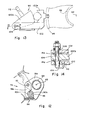
- a second embodiment comprising spaced pedestals 62, 64 carrying suitable bearings between which an elongated generally tubular fixture 66 is supported for rotation about an axis 68.
- the fixture 66 is connected at one end as at 70 to the output shaft of a gear box 72.
- the gear box is manually driven by a handle 74, the rotation of which causes the fixture 66 to rotate about axis 68.
- a holder generally indicated at 76 is carried on the fixture 66 for rotation therewith.
- the holder comprises a pair of brackets 78a fixed to and spaced axially along the fixture 66.
- the brackets carry one half 80a of a split tube.
- the other half 80b of the splittube is carried by a pair of brackets 78b which are pivotably connected to the brackets 78a by means of a cross pin 82.
- the tube half 80b and its brackets 78b are pivotable between an open position as shown by the dot-dash lines in Fig. 12, and a closed position shown by the solid lines and at which they are held by any convenient manually releasable locking mechanism such as that generally indicated at 84.
- the tube half sections 80a, 80b cooperate in defining a tubular enclosure lying on a reference axis 86.
- the reference axis 86 is parallel to the rotational axis 68 of the fixture 66.
- a first guide generally indicated at 88 is mounted on the fixture 66 at a location directly adjacent to the holder 76.
- the first guide includes brackets 90 extending radially from the fixture to support a guide plate 92, the inner edge of which defines a two-dimensional first guide path 94.
- the fixture 66 also carries a second guide in the form of a plurality of discrete pipe clamps indicated typically at 96 and arranged in a three-dimensional helical configuration. At the large diameter end of the helix, the clamps 96 are mounted on a support skirt 98 carried on .the fixture 66.
- FIG. 13 and 14 One such typical pipe clamp is shown in Figs. 13 and 14 as comprising a fixed jaw element 100a which cooperates with a movable jaw element 100b pivotally attached between a pair of support brackets 102 by means of a cross pin 104 carrying a finger 106.
- the movable jaw element is squeezed between washers 107a and 107b by means of a spring 108 so as to provide frictional resistance to prevent opening of clamp 96 when in an inverted attitude.
- Cross pin 106 is contained in a locating aperture 110 to prevent rotation of cross pin 104 thus maintaining pressure adjust-.. ment of spring 108.
- the movable jaw element may be moved between open and closed positions by means of a handle 112 having mechanical advantage over spring 108.
- a third pedestal 114 is arranged to one side of the fixture 66.
- Pedestal 114 carries a roller 116 overlying an arm 118 with a stop 120 thereon.
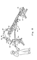
- the pipe clamps 96 and holder 76 are first opened. One end of a preheated pipe section is inserted into the open holder 76. A stop 122 locates the end of the pipe, and an angle guide 124 assists in temporarily supporting the remainder of the pipe section. The holder 76 is closed, after which a portion of the pipe is manually pre-bent against the first guide 88, as shown in Fig. 15. The stop 120 on arm 18 limits the extent of this initial bending operation. The free end of the pipe section now is supported on the arm 118 at a location underlying the roller 116.
- the fixture 66 is then rotated in the direction indicated by arrow 126 in Fig. 16, causing the pre- bent pipe to orbit about axis 68.
- the free end of the pipe section is lifted into contact with and is thereafter restrained from further rotation by the roller 116.
- the pipe section is gradually wrapped into conformity with the three-dimensional helical path defined by the fixed jaw section 100a.
- the clamp is immediately closed.
- the end of the bending operation is shown in Fig. 17. All clamps 96 remain closed until the pipe section has cooled sufficiently. Thereafter, the clamps 96 and holder 76 are opened and the pipe section, now bent into the desired three-dimensional shape, is removed and trimmed.
Landscapes
- Engineering & Computer Science (AREA)
- Mechanical Engineering (AREA)
- Bending Of Plates, Rods, And Pipes (AREA)
- Branch Pipes, Bends, And The Like (AREA)
- Shaping Of Tube Ends By Bending Or Straightening (AREA)
- Processing Of Terminals (AREA)
- Control Of Metal Rolling (AREA)
Abstract
Description
- This invention relates generally to methods of bending and bending fixtures, particularly for bending laying pipes used in the laying heads of rod and bar rolling mills.
- In one conventional laying pipe bending operation, an entire straight length of pipe is pre- heated and then manually bent and clamped along a single three dimensionally curved guide path. This operation requires a team of experienced mill personnel who must work quickly and in a carefully coordinated manner. In another conventional operation, the pipe is preheated, section by section, with each section again being manually bent and clamped along a single three dimensionally curved guide path. This operation requires considerable time, thereby limiting production to a few pipes per day. Moreover, both operations require mill personnel who must possess considerable skill and dexterity. The working conditions are relatively hazardous in that the mill personnel are intimately exposed to radiant heat from the heated pipe. Moreoever, the results of the bending operation are likely to be unsatisfactory. For example, the pipe may not take on the precise three dimensional configuration being sought, or portions of the pipe may be cross-sectionally deformed.
- Where such defects are pronounced and readily discernable, the pipe will be scrapped before being mounted for operation in a mill laying head. Here, the mill owners loss is limited to the cost of the pipe and the unsuccessful bending operation. On the other hand, where the defects are not readily discernable, they may not be noticed until after the pipe is installed and running.
- - Here, the mill owner's loss will be additionally compounded by a ruined product and costly lost production time.
- An apparatus for bending the end turn portions of dynamoelectric machine coil bars is described in US-A-4,117,707. In this apparatus the end of the coil bar is removably retained in a holder, and a portion of the retained bar is then pre-bent and permanently deformed along a first path into a two-dimensional configuration curving away from a reference axis. The pre-bent bar is then further deformed along a second path curving away from the reference axis and forming a three-dimensional configuration about a longitudinal axis parallel to the reference axis.
- According to the present invention apparatus of this type is adapted for bending a rolling mill laying pipe into a three-dimensionally curved configuration, the apparatus being characterised in that the retained pipe section is pre-bent by progressively urging the end portion of the pipe against first guide means extending along the first path to define the curvature of the pre-bent pipe section, and the pre-bent section is then further deformed by progressively urging the section against second guide means extending along the second path.
- Accordingly there is provided an improved apparatus for consistently and reliably bending a rolling mill laying pipe into a three-dimensionally curved configuration, without having to rely unduly on the experience, skill, dexterity and coordination of mill personnel. The use of respective guide means extending along the first and second paths enables particularly precise control over the final shape of the pipe section which could not be achieved using the apparatus shown in the aforesaid US-A-4,117,707.
- The second guide means may comprise a continuous helical formation adapted to progressively receive and retain the pipe section, or it may comprise a plurality of discrete guide elements spaced along the second path in a helical formation and each adapted to receive and retain a respective portion of the pipe section. Before being placed in the holder, the pipe is preferably pre-heated to a bending temperature.
- The entire operation can be carried out quickly, with consistent predictable results, and with a minimum exposure of the mill personnel to radiant heat from the preheated pipe.
- In the accompanying drawings, by way of example only:-
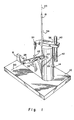
- Fig. 1 is a perspective view showing one apparatus embodying the present invention at the outset of a bending operation;
- Figs. 2 and 3 are plan and side elevational views respectively on an enlarged scale of the apparatus as it appears in Fig. I;
- Fig. 4 is a perspective view similar to Fig. 1 showing the apparatus in a subsequent stage of the bending operation;
- Fig. 5 is a sectional view through the upstanding second guide, showing the cross-sectional shape of the helical guide groove;
- Figs. 6, 7 and 8 are views similar to Fig. 5 showing alternative means for defining the helical guide path;
- Fig. 9 is a perspective view of a laying pipe formed by the apparatus of Figs. 1 to 5;
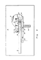
- Fig. 10 is a plan view of an alternative apparatus embodying the present invention;
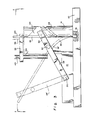
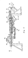
- Fig. 11 is a view in side elevation of the apparatus shown in Fig 10;
- Figs. 12 and 13 are sectional views on an enlarged scale taken respectively along lines 12-12 and 13-13 of Fig. 11;
- Fig. 14 is a sectional view taken along line 14-14 of Fig. 13; and
- Figs. 15-17 are perspective views showing the apparatus at different stages during a pipe bending operation.
- Referring initially to Figs. 1-3, the illustrated bending jig comprises a
base 10 supporting first and second fixedguide members holder 16 for removably receiving and retaining one end of astraight pipe section 18, with the longitudinal axis of the pipe section being coincident with areference axis 20. - The
first guide member 12 defines a two-dimensionalfirst bending path 22 curving away from thereference axis 20. The second guide member has asurface groove 24 defining helicalsecond bending path 26 which also curves away from thereference axis 20. - A first bending means in the form of a
lever 28 is mounted on the first guide means 12 for rotation about afirst axis 30. Thelever 28 has ahandle 32 and a pipeengaging roller 34. - A second bending means in the form of another
lever 36 is mounted on thesecond guide member 14 for rotation about asecond axis 38. Lever 36 also has ahandle 40 and apipe engaging leg 42. The second guide member is relieved as at 44 to provide clearance for theroller 34 when thehandle 32 is rotated to its start position as shown by the solid lines in Figs. 1-3. Likewise, thefirst guide member 14 terminated at 46 to allow thepipe engaging leg 42 oflever 36 to swing across thefirst bending path 22. Theaxes axis 38 being parallel to thereference axis 20. - In carrying out a bending operation with this bending jig, the
entire pipe section 18 is initially preheated to an elevated bending temperature. By way of an example, where the laying pipe consists of alloy steel ASTM A335 Grade P22, the bending operation should start at about 980°C and finish at about 740°C. After being suitably preheated, one end of the pipe section is removably inserted in theholder 16, with the longitudinal axis of the pipe section thus being held coincident with thereference axis 20. - The
first lever 28 is then rotated about thefirst axis 30 in a counterclockwise direction as viewed in Fig. 3, from its start position as shown by the solid lines in Figs. 1-3, to a finish position as shown by the dot-dash lines at 28' in Fig. 3. During this rotation, theroller 34 engages the pipe section and permanently deforms a portion . of the same against thefirst bending path 22 into the two-dimensional pre-bent shape indicated at 18'. Thelever 28 is then detached from theguide member 12, and thesecond lever 36 is rotated aboutaxis 38 in a counterclockwise direction as viewed in Fig. 1. As the dependingleg 42 moves across the plane ofguide member 12, it engages the pre-bent pipe section and causes the same to begin rotating aboutreference axis 20, as shown by the dot-dash lines in Fig. 4. This rotation aboutreference axis 20 will continue until the pre-bent pipe section comes into contact with the innermost portion of thegroove 24 defining the helicalsecond bending path 26. Thereafter, as thelever 36 continues its counterclockwise rotation about thesecond axis 38, the dependingleg 42 acts on the pipe section to permanently deform the same into thegroove 24 in conformity with the helical second bending path. The solid lines in Fig. 4 show this final bending operation in progress. - After completion of the second bending stage, the pipe is allowed to cool to a temperature at which it can be safely handled. The pipe section is then removed from the apparatus and trimmed to a finish length. The resulting three dimensionally curved piece is shown at 18" in Fig. 9.
- With the above in mind, numerous changes and modifications will undoubtedly occur to those skilled in the art. For example, as shown in Figs. 1-4 and in particular in Fig. 5, the helical second bending path can be defined by a
surface groove 24 in thesecond guide member 14. Alternatively, however, as shown in Fig. 6, the helical second bending path can be defined by a first series ofbrackets 48 which are fixed to the surface of thesecond guide member 14, and which are arranged to cooperate with associatedbolts 50 adjustably carried on a second series ofbrackets 52. - Still another arrangement is shown in Fig. 7 where, the
second guide member 14 consists of inner andouter plates 14a, 14b held in spaced relationship byspacers 54, with the helical second bending path being defined by aslit 56 in theouter plate 14b. - Yet another arrangement is shown in Fig. 8, where the helical second bending path can be defined by a first and second series of bracelets 58a, 58b, which are fixed to the surface of the
second guide member 14. - The design and manner of manipulating the
levers - Referring now to Figs. 10-17, a second embodiment is shown comprising spaced pedestals 62, 64 carrying suitable bearings between which an elongated generally
tubular fixture 66 is supported for rotation about anaxis 68. Thefixture 66 is connected at one end as at 70 to the output shaft of agear box 72. The gear box is manually driven by ahandle 74, the rotation of which causes thefixture 66 to rotate aboutaxis 68. - A holder generally indicated at 76 is carried on the
fixture 66 for rotation therewith. The holder comprises a pair ofbrackets 78a fixed to and spaced axially along thefixture 66. The brackets carry one half 80a of a split tube. Theother half 80b of the splittube is carried by a pair ofbrackets 78b which are pivotably connected to thebrackets 78a by means of across pin 82. Thetube half 80b and itsbrackets 78b are pivotable between an open position as shown by the dot-dash lines in Fig. 12, and a closed position shown by the solid lines and at which they are held by any convenient manually releasable locking mechanism such as that generally indicated at 84. When in the closed position, thetube half sections 80a, 80b cooperate in defining a tubular enclosure lying on areference axis 86. Thereference axis 86 is parallel to therotational axis 68 of thefixture 66. - A first guide generally indicated at 88 is mounted on the
fixture 66 at a location directly adjacent to theholder 76. As can be best seen in Fig. 10, the first guide includesbrackets 90 extending radially from the fixture to support aguide plate 92, the inner edge of which defines a two-dimensionalfirst guide path 94. - The
fixture 66 also carries a second guide in the form of a plurality of discrete pipe clamps indicated typically at 96 and arranged in a three-dimensional helical configuration. At the large diameter end of the helix, theclamps 96 are mounted on asupport skirt 98 carried on .thefixture 66. - One such typical pipe clamp is shown in Figs. 13 and 14 as comprising a fixed jaw element 100a which cooperates with a
movable jaw element 100b pivotally attached between a pair ofsupport brackets 102 by means of across pin 104 carrying afinger 106. The movable jaw element is squeezed between washers 107a and 107b by means of aspring 108 so as to provide frictional resistance to prevent opening ofclamp 96 when in an inverted attitude.Cross pin 106 is contained in a locatingaperture 110 to prevent rotation ofcross pin 104 thus maintaining pressure adjust-.. ment ofspring 108. The movable jaw element may be moved between open and closed positions by means of ahandle 112 having mechanical advantage overspring 108. - A
third pedestal 114 is arranged to one side of thefixture 66.Pedestal 114 carries aroller 116 overlying anarm 118 with astop 120 thereon. - The operation of the apparatus will now be described with particular reference to Figs. 15-17. The pipe clamps 96 and
holder 76 are first opened. One end of a preheated pipe section is inserted into theopen holder 76. Astop 122 locates the end of the pipe, and anangle guide 124 assists in temporarily supporting the remainder of the pipe section. Theholder 76 is closed, after which a portion of the pipe is manually pre-bent against thefirst guide 88, as shown in Fig. 15. Thestop 120 onarm 18 limits the extent of this initial bending operation. The free end of the pipe section now is supported on thearm 118 at a location underlying theroller 116. - The
fixture 66 is then rotated in the direction indicated byarrow 126 in Fig. 16, causing the pre- bent pipe to orbit aboutaxis 68. The free end of the pipe section is lifted into contact with and is thereafter restrained from further rotation by theroller 116. Thus, as thefixture 66 continues to rotate, the pipe section is gradually wrapped into conformity with the three-dimensional helical path defined by the fixed jaw section 100a. As the pipe section seats itself in the fixed jaw section 100a of each clamp, the clamp is immediately closed. The end of the bending operation is shown in Fig. 17. All clamps 96 remain closed until the pipe section has cooled sufficiently. Thereafter, theclamps 96 andholder 76 are opened and the pipe section, now bent into the desired three-dimensional shape, is removed and trimmed. - It will thus be appreciated by those skilled in the art that with either of the above-described embodiments of the present invention, a two- stage bending operation can be carried out in a minimum amount of time, by operating personnel who do not require specialized training and coordination. The resulting pipes are precisely and consistently formed with a minimum exposure of personnel to radiant heat.
Claims (14)
Priority Applications (1)
| Application Number | Priority Date | Filing Date | Title |
|---|---|---|---|
| AT84305905T ATE35635T1 (en) | 1983-09-12 | 1984-08-29 | BENDING DEVICE FOR LAYER PIPES. |
Applications Claiming Priority (2)
| Application Number | Priority Date | Filing Date | Title |
|---|---|---|---|
| US06/531,234 US4497190A (en) | 1983-09-12 | 1983-09-12 | Apparatus for bending a rolling mill laying pipe |
| US531234 | 1983-09-12 |
Publications (3)
| Publication Number | Publication Date |
|---|---|
| EP0139415A2 EP0139415A2 (en) | 1985-05-02 |
| EP0139415A3 EP0139415A3 (en) | 1985-09-18 |
| EP0139415B1 true EP0139415B1 (en) | 1988-07-13 |
Family
ID=24116812
Family Applications (1)
| Application Number | Title | Priority Date | Filing Date |
|---|---|---|---|
| EP84305905A Expired EP0139415B1 (en) | 1983-09-12 | 1984-08-29 | Bending fixtures for laying pipes |
Country Status (8)
| Country | Link |
|---|---|
| US (1) | US4497190A (en) |
| EP (1) | EP0139415B1 (en) |
| JP (1) | JPS6072616A (en) |
| AT (1) | ATE35635T1 (en) |
| BR (1) | BR8404521A (en) |
| CA (1) | CA1228284A (en) |
| DE (1) | DE3472635D1 (en) |
| IN (1) | IN161325B (en) |
Families Citing this family (2)
| Publication number | Priority date | Publication date | Assignee | Title |
|---|---|---|---|---|
| US8376287B2 (en) * | 2009-12-22 | 2013-02-19 | Siemens Industry, Inc. | Laying head pipe clamp |
| CN110479820A (en) * | 2019-08-28 | 2019-11-22 | 北京无线电测量研究所 | A kind of copper pipe pane bending apparatus |
Family Cites Families (12)
| Publication number | Priority date | Publication date | Assignee | Title |
|---|---|---|---|---|
| US1628581A (en) * | 1926-06-01 | 1927-05-10 | Frank J L Dinkel | Multiple bending apparatus |
| GB426118A (en) * | 1934-08-29 | 1935-03-27 | Robert Arthur Balfour | Improvements in and relating to the manufacture of lawn mower and the like blades |
| US2153935A (en) * | 1936-09-03 | 1939-04-11 | Imp Brass Mfg Co | Tube bender |
| US2239055A (en) * | 1938-06-04 | 1941-04-22 | David F Sawyer | Gaseous tube bending machine |
| US2228448A (en) * | 1939-10-16 | 1941-01-14 | Pittsburgh Forging Co | Manufacture of metal articles |
| US3575032A (en) * | 1968-11-12 | 1971-04-13 | Crawford Fitting Co | Tube bending tool |
| US3673844A (en) * | 1970-02-20 | 1972-07-04 | Polaroid Corp | Method and apparatus for shaping temple pieces for spectacles |
| GB1320428A (en) * | 1971-11-19 | 1973-06-13 | Miles D | Tube coiling apparatus |
| DE2514502C2 (en) * | 1975-04-03 | 1983-01-27 | Messerschmitt-Bölkow-Blohm GmbH, 8000 München | Device for bending, in particular, rectangular wires or tubes for the production of rotationally symmetrical components |
| US4117707A (en) * | 1977-09-23 | 1978-10-03 | Westinghouse Electric Corp. | Apparatus for shaping electrical coils for dynamoelectric machines |
| DE2747844C3 (en) * | 1977-10-26 | 1980-06-04 | Schmidt + Clemens Gmbh + Co, 5253 Lindlar | Device for producing a coiled tubing |
| DD209123B1 (en) * | 1982-06-09 | 1987-05-13 | Kurt Nitsch | DEVICE FOR BENDING DIVES |
-
1983
- 1983-09-12 US US06/531,234 patent/US4497190A/en not_active Expired - Lifetime
-
1984
- 1984-07-26 CA CA000459761A patent/CA1228284A/en not_active Expired
- 1984-07-30 IN IN616/DEL/84A patent/IN161325B/en unknown
- 1984-08-29 DE DE8484305905T patent/DE3472635D1/en not_active Expired
- 1984-08-29 AT AT84305905T patent/ATE35635T1/en not_active IP Right Cessation
- 1984-08-29 EP EP84305905A patent/EP0139415B1/en not_active Expired
- 1984-09-03 JP JP59182880A patent/JPS6072616A/en active Granted
- 1984-09-11 BR BR8404521A patent/BR8404521A/en not_active IP Right Cessation
Also Published As
| Publication number | Publication date |
|---|---|
| DE3472635D1 (en) | 1988-08-18 |
| BR8404521A (en) | 1985-08-06 |
| US4497190A (en) | 1985-02-05 |
| JPS6072616A (en) | 1985-04-24 |
| JPH057089B2 (en) | 1993-01-28 |
| IN161325B (en) | 1987-11-14 |
| ATE35635T1 (en) | 1988-07-15 |
| EP0139415A3 (en) | 1985-09-18 |
| EP0139415A2 (en) | 1985-05-02 |
| CA1228284A (en) | 1987-10-20 |
Similar Documents
| Publication | Publication Date | Title |
|---|---|---|
| EP1226887B1 (en) | Machine for bending elongated articles like tubes, bars, profiles or metallic wires | |
| JP3685526B2 (en) | Pipe bending machine | |
| EP0605004B1 (en) | Needle curver with automatic feed | |
| US4888971A (en) | Pipe bending machine | |
| US8904625B2 (en) | Formation and rotational apparatus and method for cylindrical workpieces | |
| US4576028A (en) | Method of making a coil spring and apparatus therefor | |
| DE19720567C2 (en) | Device for bending pipes | |
| JPH0321243B2 (en) | ||
| US3431759A (en) | Forming apparatus | |
| JPS59212124A (en) | Bending device | |
| US4552006A (en) | Bending apparatus | |
| EP0139415A2 (en) | Bending fixtures for laying pipes | |
| JPH02224820A (en) | Plant or apparatus utilizing universal straightening-bending machine | |
| US11691191B2 (en) | Roll bender with work piece support | |
| JPH07227635A (en) | Method and apparatus for end bending before spring forming of NC coiling machine | |
| CA1333355C (en) | Method and apparatus for forming a barrel coil spring | |
| EP0140859A2 (en) | A method and a device for bending a wire into a zigzag shape | |
| EP0591996B1 (en) | Needle curving apparatus | |
| JPH06198348A (en) | Roll bending method | |
| US2043665A (en) | Apparatus for forming tubes | |
| US4112727A (en) | Method and apparatus for making pipe flanges | |
| US5062288A (en) | Method and apparatus for forming bends in a tube | |
| WO2006087755A1 (en) | Bending apparatus for bar-like metal sections | |
| CN1059849C (en) | Bending apparatus for obtaining spiral pipe | |
| CN109848257A (en) | A kind of iron bucket processing iron sheet bender |
Legal Events
| Date | Code | Title | Description |
|---|---|---|---|
| PUAI | Public reference made under article 153(3) epc to a published international application that has entered the european phase |
Free format text: ORIGINAL CODE: 0009012 |
|
| AK | Designated contracting states |
Designated state(s): AT BE DE FR GB IT LU NL SE |
|
| PUAL | Search report despatched |
Free format text: ORIGINAL CODE: 0009013 |
|
| AK | Designated contracting states |
Designated state(s): AT BE DE FR GB IT LU NL SE |
|
| 17P | Request for examination filed |
Effective date: 19860220 |
|
| 17Q | First examination report despatched |
Effective date: 19861008 |
|
| R17C | First examination report despatched (corrected) |
Effective date: 19870303 |
|
| ITF | It: translation for a ep patent filed | ||
| GRAA | (expected) grant |
Free format text: ORIGINAL CODE: 0009210 |
|
| AK | Designated contracting states |
Kind code of ref document: B1 Designated state(s): AT BE DE FR GB IT LU NL SE |
|
| REF | Corresponds to: |
Ref document number: 35635 Country of ref document: AT Date of ref document: 19880715 Kind code of ref document: T |
|
| REF | Corresponds to: |
Ref document number: 3472635 Country of ref document: DE Date of ref document: 19880818 |
|
| ET | Fr: translation filed | ||
| PG25 | Lapsed in a contracting state [announced via postgrant information from national office to epo] |
Ref country code: LU Free format text: LAPSE BECAUSE OF NON-PAYMENT OF DUE FEES Effective date: 19880831 |
|
| PLBE | No opposition filed within time limit |
Free format text: ORIGINAL CODE: 0009261 |
|
| STAA | Information on the status of an ep patent application or granted ep patent |
Free format text: STATUS: NO OPPOSITION FILED WITHIN TIME LIMIT |
|
| 26N | No opposition filed | ||
| PGFP | Annual fee paid to national office [announced via postgrant information from national office to epo] |
Ref country code: SE Payment date: 19890727 Year of fee payment: 6 |
|
| PGFP | Annual fee paid to national office [announced via postgrant information from national office to epo] |
Ref country code: LU Payment date: 19890728 Year of fee payment: 6 |
|
| PGFP | Annual fee paid to national office [announced via postgrant information from national office to epo] |
Ref country code: NL Payment date: 19890831 Year of fee payment: 6 |
|
| PGFP | Annual fee paid to national office [announced via postgrant information from national office to epo] |
Ref country code: BE Payment date: 19890914 Year of fee payment: 6 |
|
| PG25 | Lapsed in a contracting state [announced via postgrant information from national office to epo] |
Ref country code: SE Effective date: 19900830 |
|
| PG25 | Lapsed in a contracting state [announced via postgrant information from national office to epo] |
Ref country code: BE Effective date: 19900831 |
|
| BERE | Be: lapsed |
Owner name: MORGAN CONSTRUCTION CY Effective date: 19900831 |
|
| PG25 | Lapsed in a contracting state [announced via postgrant information from national office to epo] |
Ref country code: NL Effective date: 19910301 |
|
| NLV4 | Nl: lapsed or anulled due to non-payment of the annual fee | ||
| ITTA | It: last paid annual fee | ||
| EUG | Se: european patent has lapsed |
Ref document number: 84305905.6 Effective date: 19910410 |
|
| PGFP | Annual fee paid to national office [announced via postgrant information from national office to epo] |
Ref country code: AT Payment date: 19980825 Year of fee payment: 15 |
|
| PGFP | Annual fee paid to national office [announced via postgrant information from national office to epo] |
Ref country code: FR Payment date: 19980828 Year of fee payment: 15 |
|
| PGFP | Annual fee paid to national office [announced via postgrant information from national office to epo] |
Ref country code: DE Payment date: 19990721 Year of fee payment: 16 |
|
| PGFP | Annual fee paid to national office [announced via postgrant information from national office to epo] |
Ref country code: GB Payment date: 19990803 Year of fee payment: 16 |
|
| PG25 | Lapsed in a contracting state [announced via postgrant information from national office to epo] |
Ref country code: AT Free format text: LAPSE BECAUSE OF NON-PAYMENT OF DUE FEES Effective date: 19990829 |
|
| PG25 | Lapsed in a contracting state [announced via postgrant information from national office to epo] |
Ref country code: FR Free format text: LAPSE BECAUSE OF NON-PAYMENT OF DUE FEES Effective date: 20000428 |
|
| REG | Reference to a national code |
Ref country code: FR Ref legal event code: ST |
|
| PG25 | Lapsed in a contracting state [announced via postgrant information from national office to epo] |
Ref country code: GB Free format text: LAPSE BECAUSE OF NON-PAYMENT OF DUE FEES Effective date: 20000829 |
|
| GBPC | Gb: european patent ceased through non-payment of renewal fee |
Effective date: 20000829 |
|
| PG25 | Lapsed in a contracting state [announced via postgrant information from national office to epo] |
Ref country code: DE Free format text: LAPSE BECAUSE OF NON-PAYMENT OF DUE FEES Effective date: 20010501 |