EP0139239A2 - Apparatus for valve motor actuation of a displacer-expander refrigerator - Google Patents
Apparatus for valve motor actuation of a displacer-expander refrigerator Download PDFInfo
- Publication number
- EP0139239A2 EP0139239A2 EP84111376A EP84111376A EP0139239A2 EP 0139239 A2 EP0139239 A2 EP 0139239A2 EP 84111376 A EP84111376 A EP 84111376A EP 84111376 A EP84111376 A EP 84111376A EP 0139239 A2 EP0139239 A2 EP 0139239A2
- Authority
- EP
- European Patent Office
- Prior art keywords
- valve
- motor
- refrigerator
- displacer
- flexible shaft
- Prior art date
- Legal status (The legal status is an assumption and is not a legal conclusion. Google has not performed a legal analysis and makes no representation as to the accuracy of the status listed.)
- Ceased
Links
Images
Classifications
-
- F—MECHANICAL ENGINEERING; LIGHTING; HEATING; WEAPONS; BLASTING
- F25—REFRIGERATION OR COOLING; COMBINED HEATING AND REFRIGERATION SYSTEMS; HEAT PUMP SYSTEMS; MANUFACTURE OR STORAGE OF ICE; LIQUEFACTION SOLIDIFICATION OF GASES
- F25B—REFRIGERATION MACHINES, PLANTS OR SYSTEMS; COMBINED HEATING AND REFRIGERATION SYSTEMS; HEAT PUMP SYSTEMS
- F25B9/00—Compression machines, plants or systems, in which the refrigerant is air or other gas of low boiling point
- F25B9/14—Compression machines, plants or systems, in which the refrigerant is air or other gas of low boiling point characterised by the cycle used, e.g. Stirling cycle
-
- F—MECHANICAL ENGINEERING; LIGHTING; HEATING; WEAPONS; BLASTING
- F25—REFRIGERATION OR COOLING; COMBINED HEATING AND REFRIGERATION SYSTEMS; HEAT PUMP SYSTEMS; MANUFACTURE OR STORAGE OF ICE; LIQUEFACTION SOLIDIFICATION OF GASES
- F25B—REFRIGERATION MACHINES, PLANTS OR SYSTEMS; COMBINED HEATING AND REFRIGERATION SYSTEMS; HEAT PUMP SYSTEMS
- F25B2309/00—Gas cycle refrigeration machines
- F25B2309/006—Gas cycle refrigeration machines using a distributing valve of the rotary type
-
- Y—GENERAL TAGGING OF NEW TECHNOLOGICAL DEVELOPMENTS; GENERAL TAGGING OF CROSS-SECTIONAL TECHNOLOGIES SPANNING OVER SEVERAL SECTIONS OF THE IPC; TECHNICAL SUBJECTS COVERED BY FORMER USPC CROSS-REFERENCE ART COLLECTIONS [XRACs] AND DIGESTS
- Y10—TECHNICAL SUBJECTS COVERED BY FORMER USPC
- Y10S—TECHNICAL SUBJECTS COVERED BY FORMER USPC CROSS-REFERENCE ART COLLECTIONS [XRACs] AND DIGESTS
- Y10S505/00—Superconductor technology: apparatus, material, process
- Y10S505/825—Apparatus per se, device per se, or process of making or operating same
- Y10S505/888—Refrigeration
- Y10S505/892—Magnetic device cooling
-
- Y—GENERAL TAGGING OF NEW TECHNOLOGICAL DEVELOPMENTS; GENERAL TAGGING OF CROSS-SECTIONAL TECHNOLOGIES SPANNING OVER SEVERAL SECTIONS OF THE IPC; TECHNICAL SUBJECTS COVERED BY FORMER USPC CROSS-REFERENCE ART COLLECTIONS [XRACs] AND DIGESTS
- Y10—TECHNICAL SUBJECTS COVERED BY FORMER USPC
- Y10T—TECHNICAL SUBJECTS COVERED BY FORMER US CLASSIFICATION
- Y10T137/00—Fluid handling
- Y10T137/2713—Siphons
- Y10T137/2774—Periodic or accumulation responsive discharge
- Y10T137/2781—With manual control
-
- Y—GENERAL TAGGING OF NEW TECHNOLOGICAL DEVELOPMENTS; GENERAL TAGGING OF CROSS-SECTIONAL TECHNOLOGIES SPANNING OVER SEVERAL SECTIONS OF THE IPC; TECHNICAL SUBJECTS COVERED BY FORMER USPC CROSS-REFERENCE ART COLLECTIONS [XRACs] AND DIGESTS
- Y10—TECHNICAL SUBJECTS COVERED BY FORMER USPC
- Y10T—TECHNICAL SUBJECTS COVERED BY FORMER US CLASSIFICATION
- Y10T137/00—Fluid handling
- Y10T137/5327—Hydrant type
- Y10T137/5456—With casing
Definitions
- the present invention pertains to a method and apparatus for producing cryogenic refrigeration and. in particular, producing such refrigeration by means of a pneumatically actuated cryogenic expander utilizing an electrically motor-driven valve.
- Patentee discloses a displacer-expander type refrigerator where the displacer is cycled against a volume of surge fluid driven through an orifice so that external driving means for the displacer are unnecessary. Work is expended by forcing the surge gas through the orifice into a surge volume chamber whereby the heat generated by such action can be removed by suitable heat exchange.
- the device of the '029 patent includes a ported rotary valve for admitting high-pressure fluid to the variable volume chamber or cold end of the refrigerator and exhausting low pressure expanded gas from the refrigerator.
- the device according the '029 patent may have more than one stage, and most current devices of this type employ two-stage refrigeration such that. at the first stage of the refrigerator. temperatures of between 35 and 85° Kelvin (K) are achieved when helium is the working fluid and temperatures of 10 to 20°K are achieved at the second stage with the same working fluid.
- K Kelvin
- Refrigerators of the type disclosed in the '029 patent are ideally suited for use in superconducting magnets and other superconducting devices.
- whole body nuclear magnetic resonance (NMR) scanners, magnetic separators and Josephson junction devices require cryostats employing liquid helium cooling.
- a refrigerator according to the '029 patent can be used to cool radiation shields and reliquefy helium boiloff in such cryostats and to minimize helium boiloff in such devices.
- the present invention provides a method and apparatus for producing cryogenic refrigeration ideally suited for NMR devices wherein the introduction of magnetic disturbances is minimized, if not eliminated, and there is no loss of refrigeration from the pneumatically actuated displacer-expander type refrigerator by separation of the valve motor from the valve disc.
- the valve motor can be mounted a suitable distance from the displacer-expander portion of the refrigerator which contains the valve and valve disc with operation of the valve disc being effected by use of a flexible shaft which is disposed within one of the gas lines used to deliver a source of high-pressure fluid (e.g.. helium) to the displacer-expander refrigerator. Maintaining the close proximity of the valve and the displacer-expander prevents the increase of void volumes and the loss of refrigeration of the device.
- a source of high-pressure fluid e.g.. helium
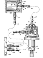
- the single figure of the drawing is a front elevational view, partially fragmentary and partially in section, illustrating the method and apparatus of the present invention.
- FIG. 10 represents the displacer expander and valve portion of a cryogenic refrigerator, such as disclosed and claimed in U.S. Patent 3.620.029. the specification of which is incorporated herein by reference.
- Refrigerator 10 includes valve 12 positioned by valve stem assembly 14.
- Valve 12 includes a coupling 16 which, in turn. is connected to a flexible shaft assembly 18.
- Valve 12 rotates to uncover ports which alternately admit and exhaust high pressure fluid from the bottom of the first stage 20 and the bottom of the second stage 22 of the refrigerator 10. Disposed within the stages of the refrigerator (20. 22) is a piston which reciprocates to produce refrigeration by forcing a gas through an orifice as disclosed in the '029 patent.
- Flexible shaft 18 is disposed within a high pressure fluid conduit 30 which is disposed between a valve housing adapter 32 on the refrigerator assembly 10 on one end, and on the other end is disposed in fluid tight relation to a motor assembly 34.
- Motor assembly 34 includes an electrically actuated motor 36 having an output shaft 38. Output shaft 38 by means of coupling 40 is connected to the end 42 of flexible shaft assembly 18 opposite to that which is connected to the valve 12.
- Motor assembly 34 includes an inlet port assembly 44 which is adapted to admit high-pressure fluid to the motor assembly 34. High-pressure fluid can be conducted through the motor assmebly to the gas conduit assembly 30 and to the valve for admission to the displacer piston in the refrigerator assembly 10.
- Fitting 44 is, in turn, by means of a fluid conduit 46 and fitting 48 connected to a suitable gas compressor 50 as is well known in the art.
- Gas compressor 50 includes a fitting 52 which is connected to a fluid pressure conduit 54 which. in turn, is connected to a fitting 56 which passes through valve assembly 13 and communicates with valve assembly 14 for exhausting low pressure fluid from the refrigerator 10 back to the compressor where it is recompressed and re-utilized as high-pressure fluid.
- refrigeration on the order of 20°K can be produced at the bottom or cold end of second stage 22.
- the device of the present invention solves the problem of delivering cryogenic refrigeration to a point of use without either loss of available refrigeration or the introduction of magnetic disturbances caused by the valve motor being within a specified distance of the device for which the refrigeration is being used.
- Prior art devices utilized separation of both the valve and the valve motor from the refrigerator portion with long interconnecting gas lines between the displacer expander and the valve motor and valve assembly. The interconnecting gas lines . become large void volumes which cause substantial refrigeration losses. Such devices were found to lose approximately 40 percent of the refrigeration in the first stage with approximately 20 percent refrigeration loss at the second stage when there was an 8-foot distance between the valve and valve motor assembly and the displacer-expander portion of the refrigerator.
- the present invention solves this problem by keeping the valve mechanism coupled to the piston assembly, thus eliminating the refrigeration losses noted above while still remotely locating the valve motor by extending its drive shaft.
- the drive shaft is mounted inside the high-pressure gas line, thus eliminating the need for a rotary gas seal. This also acts to solve any alignment or orientation problems when a flexible drive shaft is used.
- valve motor is removed from the displacer-expander porton of the refrigerator, the problem of magnetic disturbances is eliminated.
Landscapes
- Engineering & Computer Science (AREA)
- Physics & Mathematics (AREA)
- Mechanical Engineering (AREA)
- Thermal Sciences (AREA)
- General Engineering & Computer Science (AREA)
- Lift Valve (AREA)
- Magnetically Actuated Valves (AREA)
Abstract
Description
- The present invention pertains to a method and apparatus for producing cryogenic refrigeration and. in particular, producing such refrigeration by means of a pneumatically actuated cryogenic expander utilizing an electrically motor-driven valve.
- A device for producing cryogenic refrigeration of the type for which the present invention is ideally suited is disclosed and claimed in U.S. Patent 3.620.029. Patentee discloses a displacer-expander type refrigerator where the displacer is cycled against a volume of surge fluid driven through an orifice so that external driving means for the displacer are unnecessary. Work is expended by forcing the surge gas through the orifice into a surge volume chamber whereby the heat generated by such action can be removed by suitable heat exchange. The device of the '029 patent includes a ported rotary valve for admitting high-pressure fluid to the variable volume chamber or cold end of the refrigerator and exhausting low pressure expanded gas from the refrigerator. The device according the '029 patent may have more than one stage, and most current devices of this type employ two-stage refrigeration such that. at the first stage of the refrigerator. temperatures of between 35 and 85° Kelvin (K) are achieved when helium is the working fluid and temperatures of 10 to 20°K are achieved at the second stage with the same working fluid.
- Refrigerators of the type disclosed in the '029 patent are ideally suited for use in superconducting magnets and other superconducting devices. In addition, whole body nuclear magnetic resonance (NMR) scanners, magnetic separators and Josephson junction devices require cryostats employing liquid helium cooling. A refrigerator according to the '029 patent can be used to cool radiation shields and reliquefy helium boiloff in such cryostats and to minimize helium boiloff in such devices.
- In using such devices with NMR equipment, it has been found that the conventional device with the motor valve disc and expander as a single unit tended to cause magnetic disturbances in the NMR device. Separating the valve mechanism and motor from the displacer by use of long gas lines interconnecting the two led to substantial refrigeration losses because of the increased void volume in the refrigeration system.
- The present invention provides a method and apparatus for producing cryogenic refrigeration ideally suited for NMR devices wherein the introduction of magnetic disturbances is minimized, if not eliminated, and there is no loss of refrigeration from the pneumatically actuated displacer-expander type refrigerator by separation of the valve motor from the valve disc. The valve motor can be mounted a suitable distance from the displacer-expander portion of the refrigerator which contains the valve and valve disc with operation of the valve disc being effected by use of a flexible shaft which is disposed within one of the gas lines used to deliver a source of high-pressure fluid (e.g.. helium) to the displacer-expander refrigerator. Maintaining the close proximity of the valve and the displacer-expander prevents the increase of void volumes and the loss of refrigeration of the device.
- The single figure of the drawing is a front elevational view, partially fragmentary and partially in section, illustrating the method and apparatus of the present invention.
- Referring to the single figure of the drawing. 10 represents the displacer expander and valve portion of a cryogenic refrigerator, such as disclosed and claimed in U.S. Patent 3.620.029. the specification of which is incorporated herein by reference.
- Refrigerator 10 includes
valve 12 positioned byvalve stem assembly 14. Valve 12 includes acoupling 16 which, in turn. is connected to aflexible shaft assembly 18. - Valve 12 rotates to uncover ports which alternately admit and exhaust high pressure fluid from the bottom of the
first stage 20 and the bottom of thesecond stage 22 of the refrigerator 10. Disposed within the stages of the refrigerator (20. 22) is a piston which reciprocates to produce refrigeration by forcing a gas through an orifice as disclosed in the '029 patent. -
Flexible shaft 18 is disposed within a highpressure fluid conduit 30 which is disposed between avalve housing adapter 32 on the refrigerator assembly 10 on one end, and on the other end is disposed in fluid tight relation to amotor assembly 34.Motor assembly 34 includes an electrically actuatedmotor 36 having anoutput shaft 38.Output shaft 38 by means ofcoupling 40 is connected to theend 42 offlexible shaft assembly 18 opposite to that which is connected to thevalve 12.Motor assembly 34 includes aninlet port assembly 44 which is adapted to admit high-pressure fluid to themotor assembly 34. High-pressure fluid can be conducted through the motor assmebly to thegas conduit assembly 30 and to the valve for admission to the displacer piston in the refrigerator assembly 10. Fitting 44 is, in turn, by means of afluid conduit 46 and fitting 48 connected to asuitable gas compressor 50 as is well known in the art.Gas compressor 50 includes afitting 52 which is connected to afluid pressure conduit 54 which. in turn, is connected to afitting 56 which passes throughvalve assembly 13 and communicates withvalve assembly 14 for exhausting low pressure fluid from the refrigerator 10 back to the compressor where it is recompressed and re-utilized as high-pressure fluid. - With the device according to the present invention. refrigeration on the order of 20°K can be produced at the bottom or cold end of
second stage 22. - The device of the present invention solves the problem of delivering cryogenic refrigeration to a point of use without either loss of available refrigeration or the introduction of magnetic disturbances caused by the valve motor being within a specified distance of the device for which the refrigeration is being used. Prior art devices utilized separation of both the valve and the valve motor from the refrigerator portion with long interconnecting gas lines between the displacer expander and the valve motor and valve assembly. The interconnecting gas lines . become large void volumes which cause substantial refrigeration losses. Such devices were found to lose approximately 40 percent of the refrigeration in the first stage with approximately 20 percent refrigeration loss at the second stage when there was an 8-foot distance between the valve and valve motor assembly and the displacer-expander portion of the refrigerator. The present invention solves this problem by keeping the valve mechanism coupled to the piston assembly, thus eliminating the refrigeration losses noted above while still remotely locating the valve motor by extending its drive shaft. In the simplest embodiment of the invention, the drive shaft is mounted inside the high-pressure gas line, thus eliminating the need for a rotary gas seal. This also acts to solve any alignment or orientation problems when a flexible drive shaft is used.
- Once the valve motor is removed from the displacer-expander porton of the refrigerator, the problem of magnetic disturbances is eliminated.
- Having thus described my invention, what is desired to be secured by letters patent of the United States is set forth in the appended claims.
Claims (6)
Applications Claiming Priority (2)
| Application Number | Priority Date | Filing Date | Title |
|---|---|---|---|
| US06/537,472 US4538416A (en) | 1983-09-29 | 1983-09-29 | Method and apparatus for valve motor actuation of a displacer-expander refrigerator |
| US537472 | 1983-09-29 |
Publications (2)
| Publication Number | Publication Date |
|---|---|
| EP0139239A2 true EP0139239A2 (en) | 1985-05-02 |
| EP0139239A3 EP0139239A3 (en) | 1986-05-14 |
Family
ID=24142787
Family Applications (1)
| Application Number | Title | Priority Date | Filing Date |
|---|---|---|---|
| EP84111376A Ceased EP0139239A3 (en) | 1983-09-29 | 1984-09-24 | Apparatus for valve motor actuation of a displacer-expander refrigerator |
Country Status (3)
| Country | Link |
|---|---|
| US (1) | US4538416A (en) |
| EP (1) | EP0139239A3 (en) |
| CA (1) | CA1234501A (en) |
Cited By (1)
| Publication number | Priority date | Publication date | Assignee | Title |
|---|---|---|---|---|
| WO2014096194A1 (en) * | 2012-12-19 | 2014-06-26 | Siemens Plc | A mechanical arrangement for providing rotary drive |
Families Citing this family (4)
| Publication number | Priority date | Publication date | Assignee | Title |
|---|---|---|---|---|
| GB0125084D0 (en) * | 2001-10-19 | 2001-12-12 | Oxford Magnet Tech | Rotary valve |
| DE112005000199T5 (en) * | 2004-01-20 | 2007-03-15 | Sumitomo Heavy Industries, Ltd. | Reduced torque valve for a cryocooler |
| GB2430996B (en) * | 2005-10-07 | 2009-08-26 | Siemens Magnet Technology Ltd | Drive arrangement for rotary valve in a cryogenic refrigerator |
| US20090267711A1 (en) * | 2008-04-24 | 2009-10-29 | Agilent Technologies, Inc. | High frequency circuit |
Citations (9)
| Publication number | Priority date | Publication date | Assignee | Title |
|---|---|---|---|---|
| GB466572A (en) * | 1934-11-30 | 1937-05-31 | Eclipse Aviat Corp | Improvements in and relating to means for distributing fluid |
| GB567728A (en) * | 1943-07-06 | 1945-02-28 | Clarence Francis Hotchkiss Jr | Valve actuating device |
| CH313845A (en) * | 1955-02-23 | 1956-05-15 | Ruch Eduard | Device for remote actuation of valve spindles |
| US3119237A (en) * | 1962-03-30 | 1964-01-28 | William E Gifford | Gas balancing refrigeration method |
| US3205668A (en) * | 1964-01-27 | 1965-09-14 | William E Gifford | Fluid control apparatus |
| US3596875A (en) * | 1970-01-30 | 1971-08-03 | E Z Serve Inc | Remotely controlled fluid valve |
| US3598361A (en) * | 1969-06-02 | 1971-08-10 | Raymond W Crowe | Apparatus for remotely operating drain valves |
| US3908697A (en) * | 1973-10-30 | 1975-09-30 | Polymer Machinery Corp | Rotary fluid valve |
| WO1983002994A1 (en) * | 1982-02-23 | 1983-09-01 | Helix Tech Corp | Fluid actuator for cryogenic valve |
Family Cites Families (1)
| Publication number | Priority date | Publication date | Assignee | Title |
|---|---|---|---|---|
| US3620029A (en) * | 1969-10-20 | 1971-11-16 | Air Prod & Chem | Refrigeration method and apparatus |
-
1983
- 1983-09-29 US US06/537,472 patent/US4538416A/en not_active Expired - Fee Related
-
1984
- 1984-09-24 CA CA000463898A patent/CA1234501A/en not_active Expired
- 1984-09-24 EP EP84111376A patent/EP0139239A3/en not_active Ceased
Patent Citations (9)
| Publication number | Priority date | Publication date | Assignee | Title |
|---|---|---|---|---|
| GB466572A (en) * | 1934-11-30 | 1937-05-31 | Eclipse Aviat Corp | Improvements in and relating to means for distributing fluid |
| GB567728A (en) * | 1943-07-06 | 1945-02-28 | Clarence Francis Hotchkiss Jr | Valve actuating device |
| CH313845A (en) * | 1955-02-23 | 1956-05-15 | Ruch Eduard | Device for remote actuation of valve spindles |
| US3119237A (en) * | 1962-03-30 | 1964-01-28 | William E Gifford | Gas balancing refrigeration method |
| US3205668A (en) * | 1964-01-27 | 1965-09-14 | William E Gifford | Fluid control apparatus |
| US3598361A (en) * | 1969-06-02 | 1971-08-10 | Raymond W Crowe | Apparatus for remotely operating drain valves |
| US3596875A (en) * | 1970-01-30 | 1971-08-03 | E Z Serve Inc | Remotely controlled fluid valve |
| US3908697A (en) * | 1973-10-30 | 1975-09-30 | Polymer Machinery Corp | Rotary fluid valve |
| WO1983002994A1 (en) * | 1982-02-23 | 1983-09-01 | Helix Tech Corp | Fluid actuator for cryogenic valve |
Cited By (1)
| Publication number | Priority date | Publication date | Assignee | Title |
|---|---|---|---|---|
| WO2014096194A1 (en) * | 2012-12-19 | 2014-06-26 | Siemens Plc | A mechanical arrangement for providing rotary drive |
Also Published As
| Publication number | Publication date |
|---|---|
| US4538416A (en) | 1985-09-03 |
| CA1234501A (en) | 1988-03-29 |
| EP0139239A3 (en) | 1986-05-14 |
Similar Documents
| Publication | Publication Date | Title |
|---|---|---|
| US6378312B1 (en) | Pulse-tube cryorefrigeration apparatus using an integrated buffer volume | |
| US20090173083A1 (en) | Co-axial multi-stage pulse tube for helium recondensation | |
| EP0516724A1 (en) | Cryogenic cooling apparatus | |
| US6263677B1 (en) | Multistage low-temperature refrigeration machine | |
| JPH10148410A (en) | Pulse tube refrigerator | |
| US4538416A (en) | Method and apparatus for valve motor actuation of a displacer-expander refrigerator | |
| US6532748B1 (en) | Cryogenic refrigerator | |
| US7143587B2 (en) | Low frequency pulse tube system with oil-free drive | |
| US4305741A (en) | Cryogenic apparatus | |
| US4294600A (en) | Valves for cryogenic refrigerators | |
| CN1125294C (en) | Split-type gas driven stirling-pulse tube coupled refrigerator | |
| US4294077A (en) | Cryogenic refrigerator with dual control valves | |
| US5009072A (en) | Refrigerator | |
| US2123498A (en) | Refrigerating apparatus | |
| US4281517A (en) | Single stage twin piston cryogenic refrigerator | |
| Kuriyama et al. | Optimization of operational parameters for a 4K-GM refrigerator | |
| JPS6179952A (en) | Method and device for driving exclusion expansion cooling machine | |
| JP2612018B2 (en) | Cryogenic refrigerator | |
| US4475345A (en) | Refrigerator with pneumatic and working gas-supply control | |
| US11913697B1 (en) | Pneumatically actuated cryocooler | |
| JP3153624B2 (en) | Cryogenic refrigeration system | |
| JPH05126427A (en) | Stirling refrigerator | |
| Domkundwar et al. | Development and investigation of two stage modified Solvay cycle cryorefrigerator | |
| Zimmerman | Cryogenics for SQUIDS | |
| SU966292A1 (en) | Vacuum cryogenic pump operation method |
Legal Events
| Date | Code | Title | Description |
|---|---|---|---|
| PUAI | Public reference made under article 153(3) epc to a published international application that has entered the european phase |
Free format text: ORIGINAL CODE: 0009012 |
|
| AK | Designated contracting states |
Designated state(s): DE FR GB |
|
| PUAL | Search report despatched |
Free format text: ORIGINAL CODE: 0009013 |
|
| AK | Designated contracting states |
Kind code of ref document: A3 Designated state(s): DE FR GB |
|
| 17P | Request for examination filed |
Effective date: 19860618 |
|
| 17Q | First examination report despatched |
Effective date: 19861114 |
|
| STAA | Information on the status of an ep patent application or granted ep patent |
Free format text: STATUS: THE APPLICATION HAS BEEN REFUSED |
|
| 18R | Application refused |
Effective date: 19880408 |
|
| RIN1 | Information on inventor provided before grant (corrected) |
Inventor name: RIEDY, RICHARD CHARLES |