EP0139123A1 - Protective relay system - Google Patents
Protective relay system Download PDFInfo
- Publication number
- EP0139123A1 EP0139123A1 EP84109048A EP84109048A EP0139123A1 EP 0139123 A1 EP0139123 A1 EP 0139123A1 EP 84109048 A EP84109048 A EP 84109048A EP 84109048 A EP84109048 A EP 84109048A EP 0139123 A1 EP0139123 A1 EP 0139123A1
- Authority
- EP
- European Patent Office
- Prior art keywords
- values
- equation
- inductance
- electric power
- zero
- Prior art date
- Legal status (The legal status is an assumption and is not a legal conclusion. Google has not performed a legal analysis and makes no representation as to the accuracy of the status listed.)
- Granted
Links
- 230000001681 protective effect Effects 0.000 title claims description 18
- 238000000034 method Methods 0.000 claims abstract description 17
- 230000014509 gene expression Effects 0.000 claims description 8
- 238000005259 measurement Methods 0.000 claims description 7
- 238000005070 sampling Methods 0.000 claims description 6
- 230000005540 biological transmission Effects 0.000 description 15
- 230000006870 function Effects 0.000 description 6
- 238000010586 diagram Methods 0.000 description 5
- 238000011045 prefiltration Methods 0.000 description 4
- 230000004044 response Effects 0.000 description 3
- 230000001939 inductive effect Effects 0.000 description 2
- 238000001914 filtration Methods 0.000 description 1
- 238000010348 incorporation Methods 0.000 description 1
- 238000012332 laboratory investigation Methods 0.000 description 1
- 230000001052 transient effect Effects 0.000 description 1
Images
Classifications
-
- H—ELECTRICITY
- H02—GENERATION; CONVERSION OR DISTRIBUTION OF ELECTRIC POWER
- H02H—EMERGENCY PROTECTIVE CIRCUIT ARRANGEMENTS
- H02H3/00—Emergency protective circuit arrangements for automatic disconnection directly responsive to an undesired change from normal electric working condition with or without subsequent reconnection ; integrated protection
- H02H3/40—Emergency protective circuit arrangements for automatic disconnection directly responsive to an undesired change from normal electric working condition with or without subsequent reconnection ; integrated protection responsive to ratio of voltage and current
Definitions
- the present invention relates to a protective relay system of a distance measurement type.
- Protective relay systems of a distance measurement type are classified into those determining the distance in accordance with an impedance in a steady state and those utilizing a differential equation which holds even in a transient state.
- the protective relay systems of the former class have been widely adopted for a long time because stable characteristics are obtained. But they have encountered a problem in recent years when distortions in the voltage and current are greater, and filters have to be inserted to remove the distortions and this in turn causes a delay in the response due to delay in the output of the filter. For this reason, the protective relay systems of the latter class are now drawing attentions. Examples of the protective relay system belonging to this class are shown in the following publications:
- the approximation by the equation (2) has a sufficiently high accuracy as far as the variation in the current i is slow compared with the difference t 1 - t 0 , i.e., one sampling interval. In other words, a sufficient accuracy is ensured for the fundamental frequency component but the error for the second harmonic or the like is considerable. It is necessary to improve the frequency characteristics in order to attain a sufficiently high accuracy over a wide frequency range without removing the frequency components of these regions by the use of a filter.
- An object of the invention is to improve distance measurement, and particularly its frequency characteristic of a protective relay system.
- a differential equation is solved by using an approximation to determine the inductance L and to measure or discriminate the distance from the determined inductance, where v represents the voltage
- the protective relay system comprises a voltage transformer 2 and a current transformer 3 respectively detecting the voltage and the current of the transmission line, which is, in the case under consideration, assumed to be a single-phase line for the purpose of simplicity of explanation.
- An input converting circuit 4 receives the output of the transformer 2 and converts it into a signal of a suitable level, and comprises a pre-filter for removing high frequency components.
- the output v of the pre-filter constitutes the output of the input converting circuit 4.
- the input converting circuit 4 having such functions can be constructed in a known manner, so that details thereof will not be described here.
- An input converting circuit 5 is similar to the input converting circuit 4. It receives the secondary current of the current transformer 3 and converts it into a voltage signal of a suitable level, and comprises a pre-filter for removing high frequency components.
- the output i of the pre-filter constitutes the output of the input converting circuit 5.
- the reference characters v and i are also used to denote the voltage and the current of the transmission line 1.
- An AD converting circuit 6 simultaneously samples the output v of the input converting circuit 4 and the output i of the input converting circuit 5 at regular intervals and digitizes the sampled values to provide digital signals indicative of the instantaneous values of the voltage v and the current i.
- the AD converting circuit 6 having such functions can be constructed in a known manner, so that the details thereof will not be described here.
- the digital signals or data from the AD converting circuit are stored in a data memory 12.
- the data stored in the memory 12 form time series of data indicative of the instantaneous values v k , i k of the voltage and the current, with k representing the sampling time points as expressed by the consecutive integers.
- An operation unit 7 may for example be formed of a computer, such as a microcomputer, and performs arithmetic operations, judgements, and input/output operations normally required of a protective relay system, but such functions are realized in a known manner utilizing known techniques, so that details thereof will not be described here.
- the operation unit 7 also performs the following arithmetic operation to determine the inductance L of that portion of the electric power system which lies between the relay location and the fault point.
- the operation unit 7 also performs judgement in accordance with the value of L determined according to the above equation.
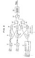
- Fig. 2 is a block diagram illustrating the functions of the operation circuit 7 of performing the above- mentioned operations.
- Adding means 12 and 13 receive the samples v m-1 , v m and i m-1 , i m and produce outputs v m + v m-1 and i m + i m-1 .
- a multiplying unit 18 receives and multiplies vn+vn-1 and i m +i m-1 and produces an output expressed by the first term of the numerator of the equation (4).
- a multiplying unit 19 receives and multiplies v m +v m-1 and i n +i n-1 and produces an output expressed by the second term of the numerator of the equation (4).
- a multiplying unit 20 receives and multiplies i n +i n-1 and and produces an output expressed by the second term of the denominator of the equation (4).
- a multiplying unit 21 receives and multiplies i m +i m-1 and
- a subtracting unit 22 subtracts the output of the unit 19 from the output 18 to determine a value expressed by the numerator of the equation (4).
- a subtracting unit 23 subtracts the output of the unit 20 from the output 21 to determine a value expressed by the denominator of the equation (4).
- a dividing unit 24 divides the output of the unit 22 by the output of the unit 23 to determine the value expressed by the entirety of the equation (4), i.e., the inductance L.
- the signal indicative of the inductance L thus determined is applied to a discriminator 26 which produces a fault signal if the inductance L is found to be within a specified range.
- the fault signal is used for producing an alarm, or for tripping a circuit breaker, not shown, provided at the relay location to protect the transmission line, or is used in combination with a signal produced as a result of protective relay operation of different type.
- the data indicative of the values v , v m-1 , i , i m-1 , i m-p-1 and i m+p are derived from the data memory 12, while the data indicative of the values v n , v n-1 , i n , i n-1 , i n-p-1 and i n+p are produced by the use of delay means within the operation unit 7 from the data supplied from the memory 12.
- the arrangement may alternatively be such that the data indicative of the values v , v n-1 , i n-1 , i n-p-1 and i n+p are also supplied from the memory 12.
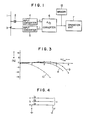
- Fig. 3 shows the performance or the accuracy of the system of the invention and a conventional system.
- the solid lines 8 and 9 illustrate two examples of error versus frequency characteristics of inductance measurement according to the invention, while the broken line 10 illustrates an example of error versus frequency characteristics of inductance measurement of a conventional system. It will be seen that the system according to the invention has much smaller errors over a wide range of frequency than the conventional system. This means that the system of the invention is less affected by waveform distortion. This will be explained next.
- the transmission line 1 is assumed to be a single-phase transmission. This is to facilitate explanation and understanding of the invention. But the invention is also applicable to protection of a multiple-phase e.g., three-phase, transmission line. For instance, two-phase fault in a three-phase transmission line can be dealt with in a manner similar to that adopted with the single-phase transmission line if one uses the line voltage and the delta current, as will be understood from a well known theory.
- Fig. 4 shows a three-phase transmission line which can be protected by a protective relay system of another embodiment of the invention.
- a three-phase transmission line including lines of phases a, b and c is shown to have a single-line grounding fault F in the phase a.
- r ab and r ac represent resistive components of the mutual-impedance
- L a represents an inductive component of the self-impedance
- L ab and L ac represent inductive components of the mutual-impedance
- i' a , i' b , i' c and j' denote time differentials of i a , i b , i c and j, respectively, as described earlier in this specification.
- Equation (19) can be solved in a similar manner as with the equation (4) as to L a and the following equation is derived.
- Equation (21) is identical to the equation (4) except that the currents i , i b , i and synthetic values i and j are used.
- equation (21) is a more generalized form
- equation (4) is a specific form where the synthetic values i and j of the equation (21) are (or happen to be) i.
- the invention is applicable not only to a situation where, as has been described, the value of the inductance L or L a is first determined and then judgement is made as to whether the determined inductance is within a specified range, but also to a situation.where judgement is made whether the inductance is larger or smaller than a predetermined value. Therefore, instead of first determining the inductance L according to the equation (4) and then judging whether or not one may use the following expression.
- the right side of the expression (23) may be a very small positive value, rather than zero, to increase the stability of operation of the relay device. This itself is also a well known technique.
- the determined value of the inductance may be in combination with other value or values to calculate some other quantity, and a signal to be used for protection is produced in accordance with the resultant value of such other quantity.
- the signal to be used for protection may not necessarily be a fault signal for producing an alarm or for tripping a circuit breaker, but may be a signal used in combination with a signal produced as a result of protective relay operation or function of a different type.
Landscapes
- Emergency Protection Circuit Devices (AREA)
- Locating Faults (AREA)
Abstract

- v represents the voltage,
- i represents the current,
- R represents the resistance,
- t represents the time,
- tk and tx-1 represent time points,
- ik+p and ik-P-1 represent values of the current i for time points represented by tk+p and tk-p-1,
- p represents integers (0, 1, .... N),
- N represents a natural number,
- Kp (p = 0, 1, .... N) represents constants, with at least Ko and K, being values other than zero and being so determined that the errors in the approximation for the inductance is zero for specified frequencies.
Description
- The present invention relates to a protective relay system of a distance measurement type.
- Protective relay systems of a distance measurement type are classified into those determining the distance in accordance with an impedance in a steady state and those utilizing a differential equation which holds even in a transient state. The protective relay systems of the former class have been widely adopted for a long time because stable characteristics are obtained. But they have encountered a problem in recent years when distortions in the voltage and current are greater, and filters have to be inserted to remove the distortions and this in turn causes a delay in the response due to delay in the output of the filter. For this reason, the protective relay systems of the latter class are now drawing attentions. Examples of the protective relay system belonging to this class are shown in the following publications:
- i) Japanese Patent Application Publication No. 31747/1978, "A system for measuring an impedance component in an electric power system".
- ii) IEEE Paper F77 052-4, W. D. Breingan et al, "The Laboratory Investigation of a Digital System for the protection of Transmission Lines".
- These systems both determine the inductance L of an electric power system, e.g., a transmission line, by solving a differential equation


- The approximation by the equation (2) has a sufficiently high accuracy as far as the variation in the current i is slow compared with the difference t1 - t0, i.e., one sampling interval. In other words, a sufficient accuracy is ensured for the fundamental frequency component but the error for the second harmonic or the like is considerable. It is necessary to improve the frequency characteristics in order to attain a sufficiently high accuracy over a wide frequency range without removing the frequency components of these regions by the use of a filter.
- An object of the invention is to improve distance measurement, and particularly its frequency characteristic of a protective relay system.
- According to the invention, there is provided a method and a system for electric power system protection, wherein a differential equation


- i represents the current,
- R represents the resistance,
- t represents the time,
- t k and tk-1 represent time points,
- ik+p and i k-p-1 represent values of the current i for time points represented by tk+p and tk-p-1,
- p represents integers (0, 1, ..... N),
- N represents a natural number,
- Kp (p = 0, 1, ...N) represents constants, with at least KO and K1 being values other than zero and being so determined that the errors in the approximation for the inductance is zero for specified frequencies.
- In the accompanying drawings:
- Fig. 1 is a block diagram showing hardware of a protective relay system of an embodiment of the invention;
- Fig. 2 is a block diagram showing functions of the operation unit of the system of Fig. 1;
- Fig. 3 is a characteristic diagram for comparing the conventional system and the system of the invention; and
- Fig. 4 is a diagram showing another example of the transmission line for which the protective relay system according to the invention can be used.
- Referring now more particularly to Fig. 1, there is shown a hardware structure of the protective relay system in connection with a
transmission line 1, forming an example of electric power system to be protected by the protective relay system. The protective relay system comprises avoltage transformer 2 and acurrent transformer 3 respectively detecting the voltage and the current of the transmission line, which is, in the case under consideration, assumed to be a single-phase line for the purpose of simplicity of explanation. Aninput converting circuit 4 receives the output of thetransformer 2 and converts it into a signal of a suitable level, and comprises a pre-filter for removing high frequency components. The output v of the pre-filter constitutes the output of theinput converting circuit 4. Theinput converting circuit 4 having such functions can be constructed in a known manner, so that details thereof will not be described here. Aninput converting circuit 5 is similar to theinput converting circuit 4. It receives the secondary current of thecurrent transformer 3 and converts it into a voltage signal of a suitable level, and comprises a pre-filter for removing high frequency components. The output i of the pre-filter constitutes the output of theinput converting circuit 5. The reference characters v and i are also used to denote the voltage and the current of thetransmission line 1. - An
AD converting circuit 6 simultaneously samples the output v of theinput converting circuit 4 and the output i of theinput converting circuit 5 at regular intervals and digitizes the sampled values to provide digital signals indicative of the instantaneous values of the voltage v and the current i. TheAD converting circuit 6 having such functions can be constructed in a known manner, so that the details thereof will not be described here. The digital signals or data from the AD converting circuit are stored in adata memory 12. Thus the data stored in thememory 12 form time series of data indicative of the instantaneous values vk, ik of the voltage and the current, with k representing the sampling time points as expressed by the consecutive integers. - An
operation unit 7 may for example be formed of a computer, such as a microcomputer, and performs arithmetic operations, judgements, and input/output operations normally required of a protective relay system, but such functions are realized in a known manner utilizing known techniques, so that details thereof will not be described here. Theoperation unit 7 also performs the following arithmetic operation to determine the inductance L of that portion of the electric power system which lies between the relay location and the fault point.
integers 0, 1, ....N N represents a predetermined natural number Kp (p = 0, 1, ...N) represents a constant, with at least K0 and K1 being values other than zero and being so determined, in a manner described later, that the errors in the approximation for the inductance is zero for specified or selected frequencies. - The
operation unit 7 also performs judgement in accordance with the value of L determined according to the above equation. - Fig. 2 is a block diagram illustrating the functions of the
operation circuit 7 of performing the above- mentioned operations. - Adding means 12 and 13 receive the samples vm-1, vm and im-1, im and produce outputs vm + vm-1 and im + im-1.
- A differentiating
means 14 receives the samples im+p, im-p-1 (p = 0, 1, ....N), namely, ...., im-2, im-1, im, im+1, .... and produces an output expressed by:
- The outputs of the adding
means means 14 are passed through respective delay means 15, 16 and 17 having a delay time (n-m) to result in:


multiplying unit 18 receives and multiplies vn+vn-1 and im+im-1 and produces an output expressed by the first term of the numerator of the equation (4). Amultiplying unit 19 receives and multiplies vm+vm-1 and in+in-1 and produces an output expressed by the second term of the numerator of the equation (4). Amultiplying unit 20 receives and multiplies in+in-1 and
multiplying unit 21 receives and multiplies im+im-1 and
- A
subtracting unit 22 subtracts the output of theunit 19 from theoutput 18 to determine a value expressed by the numerator of the equation (4). Asubtracting unit 23 subtracts the output of theunit 20 from theoutput 21 to determine a value expressed by the denominator of the equation (4). A dividingunit 24 divides the output of theunit 22 by the output of theunit 23 to determine the value expressed by the entirety of the equation (4), i.e., the inductance L. - The signal indicative of the inductance L thus determined is applied to a
discriminator 26 which produces a fault signal if the inductance L is found to be within a specified range. The fault signal is used for producing an alarm, or for tripping a circuit breaker, not shown, provided at the relay location to protect the transmission line, or is used in combination with a signal produced as a result of protective relay operation of different type. - In the example described with reference to Fig. 2, the data indicative of the values v , vm-1, i , im-1, im-p-1 and im+p are derived from the
data memory 12, while the data indicative of the values vn, vn-1, in, in-1, in-p-1 and in+p are produced by the use of delay means within theoperation unit 7 from the data supplied from thememory 12. - However, the arrangement may alternatively be such that the data indicative of the values v , vn-1, in-1, in-p-1 and in+p are also supplied from the
memory 12. - Now explanation as to why the incorporation of the approximate expression (3) in the equation (1) leads to the equation (4), and why the use of the approximate expression (3) ensures a high accuracy will be given. From the equation (1), we obtain,


- If we substitute the equations (8) and (9) in the equations (6) and (7), we will obtain the equation (4).
- Fig. 3 shows the performance or the accuracy of the system of the invention and a conventional system. The
solid lines broken line 10 illustrates an example of error versus frequency characteristics of inductance measurement of a conventional system. It will be seen that the system according to the invention has much smaller errors over a wide range of frequency than the conventional system. This means that the system of the invention is less affected by waveform distortion. This will be explained next. - The true value Lt of the inductance, which is obtained by solving the equations (6) and (7) without using the approximation of the expressions (8) and (9), is given by:

- From the equations (4) and (10), the error ratio E is given by:

- To examine the frequency characteristic of the error ratio ε, the angular frequency and the phase are denoted by
wand 6, respectively, and if


- Utilizing these, the equation (11) can be rewritten as:

- This is accomplished by solving simultaneous equations derived from the equation (18) by putting ε = 0 and substituting the specific values ω1, w2 for ω. As an example, a set of two simultaneous equations derived when only K0, K1 are not zero, and K 2, K 3, K4, etc are zero are shown below:


- The
solid line 8 in Fig. 3 represents an example where w1T = 30°, ω2/ω 1 = 2, while thesolid line 9 represents an example where w1T = 30°, ω2/ω 1 = 3. If ω1 is the fundamental angular frequency, ε is zero at the fundamental frequency and at a frequency twice the fundamental frequency with the former example, while e is zero at the fundamental frequency and at a frequency three times the fundamental frequency with the latter example. In each case, the error ratio is very small in the area proximate to the frequency where ε = 0. - In contrast, the conventional system uses the approximation of the equation (2) so that the error ratio is 0 at ω = 0 and the error ratio ε increases with the angular frequency ω. The
broken line 10 in Fig. 3 represents an example where ω1T = 30°. - It has been assumed that K0 and K1 are other than zero and K2, K3, K4, etc., are zero. But if K2, K31 K4, etc. are also set to be a value, to make ε = 0 at respective frequencies, the frequency characteristic is further improved. However, with a larger number of K which are not zero, it takes a longer time for calculation and delay in response becomes longer. Accordingly, a compromise must be made between a higher accuracy and a quick response. It has however been found that using two non-zero constants K0, K1 to obtain ε = 0 at two frequencies yields practically satisfactory results.
- In describing the embodiment of Fig. 1, the
transmission line 1 is assumed to be a single-phase transmission. This is to facilitate explanation and understanding of the invention. But the invention is also applicable to protection of a multiple-phase e.g., three-phase, transmission line. For instance, two-phase fault in a three-phase transmission line can be dealt with in a manner similar to that adopted with the single-phase transmission line if one uses the line voltage and the delta current, as will be understood from a well known theory. - Fig. 4 shows a three-phase transmission line which can be protected by a protective relay system of another embodiment of the invention. As is seen, a three-phase transmission line including lines of phases a, b and c is shown to have a single-line grounding fault F in the phase a. If the voltage at the location where the protective relay system is provided is denoted by v, and the currents of the respective phases a, b and c are denoted by ia, ib and ic, the following equation, which itself is well known, holds:


- rab and rac represent resistive components of the mutual-impedance,
- La represents an inductive component of the self-impedance,
- Lab and Lac represent inductive components of the mutual-impedance,
- i'a, i'b, i'c and j' denote time differentials of i a, i b, ic and j, respectively, as described earlier in this specification.
- The equation (19) can be solved in a similar manner as with the equation (4) as to La and the following equation is derived.

- Here, the suffixes m, n and p and the constants N and K are similar to those of the same reference characters P in the equation (4). The equation (21) is identical to the equation (4) except that the currents i , ib, i and synthetic values i and j are used. Conversely speaking, we may regard the equation (21) as a more generalized form, and the equation (4) as a specific form where the synthetic values i and j of the equation (21) are (or happen to be) i.
- The invention is applicable not only to a situation where, as has been described, the value of the inductance L or La is first determined and then judgement is made as to whether the determined inductance is within a specified range, but also to a situation.where judgement is made whether the inductance is larger or smaller than a predetermined value. Therefore, instead of first determining the inductance L according to the equation (4) and then judging whether or not


- to make judgement directly. This is a commonly adopted technique. Still alternatively, the right side of the expression (23) may be a very small positive value, rather than zero, to increase the stability of operation of the relay device. This itself is also a well known technique.
- It should therefore be understood that the invention embraces any method or system in which the inductance is measured or discriminated according to the concept expressed by the equations described or any equivalent equations.
- Instead of having a fault signal produced solely in accordance with the result of the determination of the inductance, the determined value of the inductance may be in combination with other value or values to calculate some other quantity, and a signal to be used for protection is produced in accordance with the resultant value of such other quantity.
- The signal to be used for protection may not necessarily be a fault signal for producing an alarm or for tripping a circuit breaker, but may be a signal used in combination with a signal produced as a result of protective relay operation or function of a different type.
- The principle of the invention described with reference to the expressions (19), (20), (21), with which it was assumed that the synthetic values are of different types of electric quantities, e.g., the currents of the different phases i , ib' ic, is also applicable to a situation where the synthetic values are of the same type of electric quantities. For instance, if synthetic values uk and wk are defined as:

- As has been described, according to the invention, a greater number of sample values are used for the approximation of differentials, and thereby the frequency characteristic of the distance measurement is improved.
Claims (12)


Applications Claiming Priority (2)
| Application Number | Priority Date | Filing Date | Title |
|---|---|---|---|
| JP58144988A JPS6039312A (en) | 1983-08-10 | 1983-08-10 | Protective relaying device |
| JP144988/83 | 1983-08-10 |
Publications (2)
| Publication Number | Publication Date |
|---|---|
| EP0139123A1 true EP0139123A1 (en) | 1985-05-02 |
| EP0139123B1 EP0139123B1 (en) | 1988-05-11 |
Family
ID=15374861
Family Applications (1)
| Application Number | Title | Priority Date | Filing Date |
|---|---|---|---|
| EP84109048A Expired EP0139123B1 (en) | 1983-08-10 | 1984-07-31 | Protective relay system |
Country Status (4)
| Country | Link |
|---|---|
| US (1) | US4577254A (en) |
| EP (1) | EP0139123B1 (en) |
| JP (1) | JPS6039312A (en) |
| DE (1) | DE3471209D1 (en) |
Cited By (2)
| Publication number | Priority date | Publication date | Assignee | Title |
|---|---|---|---|---|
| EP2485354A1 (en) * | 2011-02-07 | 2012-08-08 | Rolls-Royce plc | Protection system for an electrical power network based on the inductance of a network section |
| CN104125595A (en) * | 2013-04-25 | 2014-10-29 | 华为技术有限公司 | Fault location and isolation method and detection equipment |
Families Citing this family (12)
| Publication number | Priority date | Publication date | Assignee | Title |
|---|---|---|---|---|
| JPS60180424A (en) * | 1984-02-28 | 1985-09-14 | 三菱電機株式会社 | Shorting distance relay |
| JPH0828934B2 (en) * | 1984-07-31 | 1996-03-21 | 株式会社東芝 | Protection control device |
| JPS61112527A (en) * | 1984-11-07 | 1986-05-30 | 三菱電機株式会社 | Digital distance relay |
| JPS6240019A (en) * | 1985-08-13 | 1987-02-21 | 三菱電機株式会社 | Digital distance relay system |
| AU603871B2 (en) * | 1987-03-03 | 1990-11-29 | Mitsubishi Denki Kabushiki Kaisha | Digital locator |
| SE459946B (en) * | 1987-12-29 | 1989-08-21 | Asea Ab | RELAY PROTECTION WITH SELECTIVE PHASE SELECTION FOR DOUBLE CABLES |
| US5483462A (en) * | 1990-05-07 | 1996-01-09 | Cornell Research Foundation, Inc. | On-line method for determining power system transient stability |
| JP3119541B2 (en) * | 1993-03-25 | 2000-12-25 | 株式会社東芝 | Frequency detection method |
| US5506789A (en) * | 1993-10-15 | 1996-04-09 | The Texas A & M University System | Load extraction fault detection system |
| JP3790053B2 (en) | 1998-10-14 | 2006-06-28 | 株式会社東芝 | Distance relay |
| AT408921B (en) * | 1999-04-13 | 2002-04-25 | Lothar Dipl Ing Dr Tec Fickert | MEASURING SYSTEM FOR REMOTELY MEASURING CURRENT AND VOLTAGE IN ELECTRIC POWER NETWORKS |
| CN102645614A (en) * | 2012-04-26 | 2012-08-22 | 郭振威 | Transmission line directional element based on high frequency sub-band signal handling capacity difference value of filter bank |
Family Cites Families (5)
| Publication number | Priority date | Publication date | Assignee | Title |
|---|---|---|---|---|
| JPS52100149A (en) * | 1976-02-18 | 1977-08-22 | Tokyo Electric Power Co Inc:The | Digital failure point evaluating unit |
| JPS595220B2 (en) * | 1976-09-07 | 1984-02-03 | カルプ工業株式会社 | resin composition |
| JPS5592514A (en) * | 1978-12-28 | 1980-07-14 | Tokyo Shibaura Electric Co | Digital protection relay |
| JPS55127829A (en) * | 1979-03-27 | 1980-10-03 | Tokyo Shibaura Electric Co | Digital distance relay unit |
| US4300182A (en) * | 1979-08-09 | 1981-11-10 | Schweitzer Edmund O Iii | Metering and protection system for an A.C. power system |
-
1983
- 1983-08-10 JP JP58144988A patent/JPS6039312A/en active Granted
-
1984
- 1984-07-31 DE DE8484109048T patent/DE3471209D1/en not_active Expired
- 1984-07-31 EP EP84109048A patent/EP0139123B1/en not_active Expired
- 1984-08-06 US US06/637,722 patent/US4577254A/en not_active Expired - Lifetime
Non-Patent Citations (4)
| Title |
|---|
| ETZ ARCHIV, vol. 4, no. 1, 1982; J. SCHLABBACH et al. "Mikrorechner als Distanzschutzrelais für Netze mit Erdschlu~kompensation", pages 9-14 * |
| I.E.E. PROCEEDINGS SECTION A-I, vol. 130, no. 3, part. C, May 1983, Old-Working, GB; A.T. JOHNS et al. "New ultra-high-speed distance protection using finite-transform techniques", pages 127-138 * |
| IEEE TRANSACTIONS ON POWER APPARATUS AND SYSTEMS, vol. PAS-100, no. 11, November 1981; T.C. CHENG et al. "The effect of subsynchronous current on a static MHO type distance relay", pages 4562-4570 * |
| IEEE TRANSACTIONS ON POWER APPARATUS AND SYSTEMS, vol. PAS-98, no. 5, September/October 1979; M.M. CHEN et al. "Field experience with a digital system for transmission line protection", pages 1796-1804 * |
Cited By (4)
| Publication number | Priority date | Publication date | Assignee | Title |
|---|---|---|---|---|
| EP2485354A1 (en) * | 2011-02-07 | 2012-08-08 | Rolls-Royce plc | Protection system for an electrical power network based on the inductance of a network section |
| US8842401B2 (en) | 2011-02-07 | 2014-09-23 | Rolls-Royce Plc | Protection system for an electrical power network |
| CN104125595A (en) * | 2013-04-25 | 2014-10-29 | 华为技术有限公司 | Fault location and isolation method and detection equipment |
| CN104125595B (en) * | 2013-04-25 | 2018-05-11 | 华为技术有限公司 | Fault location and the method and detection device of isolation |
Also Published As
| Publication number | Publication date |
|---|---|
| DE3471209D1 (en) | 1988-06-16 |
| EP0139123B1 (en) | 1988-05-11 |
| US4577254A (en) | 1986-03-18 |
| JPS6039312A (en) | 1985-03-01 |
| JPH0320969B2 (en) | 1991-03-20 |
Similar Documents
| Publication | Publication Date | Title |
|---|---|---|
| EP0139123B1 (en) | Protective relay system | |
| US4314199A (en) | Method for locating a fault point on a transmission line | |
| US5446387A (en) | Method and a device for determining a fault on a transmission line | |
| US7180300B2 (en) | System and method of locating ground fault in electrical power distribution system | |
| Szafran et al. | Power system frequency estimation | |
| US6397156B1 (en) | Impedance measurement system for power system transmission lines | |
| Chowdhury et al. | Power system fault detection and state estimation using Kalman filter with hypothesis testing | |
| US4261038A (en) | Protection of electrical power supply systems | |
| RU2178582C2 (en) | Device for comparing two signals; method and device for shaping transient signals | |
| EP0224749B1 (en) | Digital fault locator | |
| US6989977B2 (en) | Digital directional relay | |
| EP0581015B1 (en) | Method for determining fault currents on transmission lines and a fault current filter for carrying out the method | |
| US6173216B1 (en) | Protective relay with improved, sub-window cosine filter | |
| EP0371192B1 (en) | Electric quantity detecting method | |
| EP0214483B1 (en) | Method for measuring distance in digital distance relays | |
| EP0718949A1 (en) | Protective relay system with spacial difference filter and summing filter | |
| US6115675A (en) | Double interpolation anti-skew compensation of sampled analog data points in a protective relay | |
| US4398255A (en) | Polyphase angle estimator | |
| KR100232764B1 (en) | Apparatus and method for measuring impedance of a digital distance relay | |
| EP0367563B1 (en) | Detector of quantity of electricity | |
| Bertrand et al. | Earth-fault detection in a compensated earthed network, without any voltage measurement: a new protection principle | |
| SU1525633A1 (en) | Device for determining insulation damage of electric conductor | |
| JPS596137Y2 (en) | Insulation monitoring device for rotating machine windings | |
| JPS6311848B2 (en) | ||
| Lian et al. | Identifying an error source in the differential equation approach for the transmission line fault location algorithm |
Legal Events
| Date | Code | Title | Description |
|---|---|---|---|
| PUAI | Public reference made under article 153(3) epc to a published international application that has entered the european phase |
Free format text: ORIGINAL CODE: 0009012 |
|
| 17P | Request for examination filed |
Effective date: 19840829 |
|
| AK | Designated contracting states |
Designated state(s): CH DE FR GB LI |
|
| 17Q | First examination report despatched |
Effective date: 19860205 |
|
| GRAA | (expected) grant |
Free format text: ORIGINAL CODE: 0009210 |
|
| AK | Designated contracting states |
Kind code of ref document: B1 Designated state(s): CH DE FR GB LI |
|
| REF | Corresponds to: |
Ref document number: 3471209 Country of ref document: DE Date of ref document: 19880616 |
|
| ET | Fr: translation filed | ||
| PLBE | No opposition filed within time limit |
Free format text: ORIGINAL CODE: 0009261 |
|
| STAA | Information on the status of an ep patent application or granted ep patent |
Free format text: STATUS: NO OPPOSITION FILED WITHIN TIME LIMIT |
|
| 26N | No opposition filed | ||
| REG | Reference to a national code |
Ref country code: GB Ref legal event code: IF02 |
|
| PGFP | Annual fee paid to national office [announced via postgrant information from national office to epo] |
Ref country code: FR Payment date: 20030711 Year of fee payment: 20 |
|
| PGFP | Annual fee paid to national office [announced via postgrant information from national office to epo] |
Ref country code: GB Payment date: 20030730 Year of fee payment: 20 Ref country code: CH Payment date: 20030730 Year of fee payment: 20 |
|
| PGFP | Annual fee paid to national office [announced via postgrant information from national office to epo] |
Ref country code: DE Payment date: 20030807 Year of fee payment: 20 |
|
| PG25 | Lapsed in a contracting state [announced via postgrant information from national office to epo] |
Ref country code: LI Free format text: LAPSE BECAUSE OF EXPIRATION OF PROTECTION Effective date: 20040730 Ref country code: GB Free format text: LAPSE BECAUSE OF EXPIRATION OF PROTECTION Effective date: 20040730 Ref country code: CH Free format text: LAPSE BECAUSE OF EXPIRATION OF PROTECTION Effective date: 20040730 |
|
| REG | Reference to a national code |
Ref country code: GB Ref legal event code: PE20 |
|
| REG | Reference to a national code |
Ref country code: CH Ref legal event code: PL |