EP0138529A2 - Adaptive prediction of image data - Google Patents
Adaptive prediction of image data Download PDFInfo
- Publication number
- EP0138529A2 EP0138529A2 EP84306809A EP84306809A EP0138529A2 EP 0138529 A2 EP0138529 A2 EP 0138529A2 EP 84306809 A EP84306809 A EP 84306809A EP 84306809 A EP84306809 A EP 84306809A EP 0138529 A2 EP0138529 A2 EP 0138529A2
- Authority
- EP
- European Patent Office
- Prior art keywords
- predictor
- halftone
- previous
- predictors
- current
- Prior art date
- Legal status (The legal status is an assumption and is not a legal conclusion. Google has not performed a legal analysis and makes no representation as to the accuracy of the status listed.)
- Withdrawn
Links
Images


Classifications
-
- H—ELECTRICITY
- H04—ELECTRIC COMMUNICATION TECHNIQUE
- H04N—PICTORIAL COMMUNICATION, e.g. TELEVISION
- H04N19/00—Methods or arrangements for coding, decoding, compressing or decompressing digital video signals
- H04N19/90—Methods or arrangements for coding, decoding, compressing or decompressing digital video signals using coding techniques not provided for in groups H04N19/10-H04N19/85, e.g. fractals
-
- H—ELECTRICITY
- H04—ELECTRIC COMMUNICATION TECHNIQUE
- H04N—PICTORIAL COMMUNICATION, e.g. TELEVISION
- H04N1/00—Scanning, transmission or reproduction of documents or the like, e.g. facsimile transmission; Details thereof
- H04N1/41—Bandwidth or redundancy reduction
- H04N1/411—Bandwidth or redundancy reduction for the transmission or storage or reproduction of two-tone pictures, e.g. black and white pictures
- H04N1/413—Systems or arrangements allowing the picture to be reproduced without loss or modification of picture-information
- H04N1/417—Systems or arrangements allowing the picture to be reproduced without loss or modification of picture-information using predictive or differential encoding
Definitions
- This invention relates to a system for compressing or compacting halftone, line and text data where resolution and halftone screen frequency may be unknown, and more particularly to a circuit and method for adaptive predicting which uses a plurality of predictor patterns but which does not require transmission of additional code to the receiver to identify the particular pattern used.
- an image reproducing system compress images well regardless of their composition. Since prediction is based on the correlation between neighboring data bits, a problem arises from the fact that the correlation between bits in documents containing halftone pictures is fundamentally different from that in documents containing text and line drawings. Predictors that work well for one do not work well for the other. Furthermore, the correlation in documents containing halftones is highly dependent upon the scanning resolution and the screen frequency of the halftones. Given a document composed of text, a halftone picture from a magazine, and a halftone picture from a newspaper, no single predictor would perform well on all regions of the document.
- the present invention aims at overcoming these drawbacks and accordingly provides a system and method for adaptive prediction which are as claimed in the respective appended claims.
- the present invention is defined by a set of simple predictors and an algorithm for selecting the appropriate predictor for each current data block.
- both the predictor and the depredictor select the predictor (depredictor) for the current data block based on which predictor would have performed best (least errors) on the previous data block. If a particular predictor would have worked well on the previous data block, it is likely that it will work well on the next data block. Since the data necessary for making the decision are available to both transmitter and receiver, no extra data need be transmitted.
- the general rule is that the predictor that performed best on the previous block will be used for the current block, and that in case of ties, the predictor used previously (or the predictor in the class that was used previously) will be used. There is an exception, and that is for halftones, where the pitch inevitably remains fixed for the duration of the image. To take advantage of this, a new halftone predictor will not be selected unless it performs better than the previously selected one for two consecutive blocks.
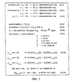
- Figure 1 mathematically describes the simplest embodiment of the present invention in which there are only two predictors in the system.
- equation A-14 where a data block is assumed to be one byte, the error byte for any byte X. is equal to the error byte of the predictor selected from the previous byte, p i-1 , operating on X..
- Equation A-13 indicates how a predictor is assigned to the (i-1) th byte in this embodiment.
- the error counts of the predictors Pm and Pn operating on X i-1 are compared. If the error count of Pm is less than that of Pn, Pm is assigned to p i-1 .
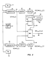
- Figure 2 shows a block diagram of the simple adaptive predictor described above.
- the predicted values of X i from predictors Pn, 10, and Pm, 12, are input along with the actual value of X i , 14, to comparators 16 and 18 respectively.
- the outputs of comparators 16 and 18 are the error bytes E [Pn (X i )], 20, and E [Pm (X i )] , 22.
- These error bytes 20 and 22 are input to counters 24 and 26 where the number of error bits in each error byte is counted.
- the error bytes 20 and 22 are also input to multiplexor 46.
- the outputs of counters 24 and 26 are the error counts C [E [Pn(X i )]] 28, and C[E[Pm(X i )]], 30.
- the error counts are input to and delayed by delays 32 and 34 so that the output of the delays is C [E[Pn(X i-1 )]], 36 and C [E [Pm (X i-1 )]], 38, respectively.
- Signals 36 and 38 are the error counts of the predictors Pn and Pm from the previous byte and indicate the performance of the predictors Pn, 10 and Pm, 12 on the byte X i-1 . These error counts are input to selector 40 along with information indicating which predictor performed best on the previous byte, signal 50.
- Selector 40 compares the error counts and selects the smaller, with ties resolved in favor of the predictor selected on the previous byte.
- the output of selector 40, signal 44 indicates which predictor performed best on X i-1 . This is the predictor assigned to p i-1 .
- Signal 44 is input to delay 42 and the select input of multiplexor 46. Signal 44 is delayed by delay 42 so that the output of delay 42, signal 50, indicates which predictor performed best on the previous cycle.
- signal 44 forces the selection, as the output of multiplexor 46, the error byte of the predictor assigned to p i-1 operating on X i , E [p i-1 (X i )]
- This signal, signal 48, is the output of the predictor ready for encoding.
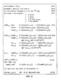
- the adaptive predictor algorithm of the present invention is described mathematically in Figure 3.
- the adaptive process here is basically the same as in the simplified example above, i.e., the predictor selected for predicting a particular byte or data block is based on a comparison of predictor performance on previous bytes or data blocks, it differs in that the selection process is segmented. Specifically, the process takes place in two steps. In the first step, the past performance of the halftone predictors is compared and in a separate comparison the past performance of the nonhalftone predictors are evaluated. The two best predictors from the first comparisons, ht i-2 and nonHT i-1 , are compared in the second step and the better of the two, final i-1 , is used to predict the current byte.
- the error byte for any byte X i is equal to the error byte resulting from final. operating on X..
- the nonhalftone predictor selection process described in Figure 3 by equation A-8 is similar to the simple algorithm described in Figure 1.
- the nonhalftone predictor set would consist of two nonhalftone predictors: Bitabove and PreBit.
- the bit pattern for such a set is shown in Figure 5.
- B-1 the Bitabove predictor predicts that the actual bit is the same as the corresponding bit in the previous scan line.
- B-2 shows that PreBit predicts that the actual bit is the same as the previous bit.
- the performance of Bitabove and PreBit operating on the previous byte, X i-1 is compared.
- the halftone ' predictor selection process described in Figure 3 by equations A-10 and A-11 is a two-tiered process slightly more complex than those previously described. This results in the halftone predictor which had the best performance two bytes previously, ht i-2 , being used in the final step of the comparison.
- the bit pattern for such a set is shown in Figure 5.
- Halftone prediction is based on the repetitive nature of halftone images, that is, the fact that halftone images consist of periodic repetition of black and white bits. So, as described in B-3, each halftone predictor predicts that the actual bit is the same as a bit a certain number of bits back.
- the first tier in the halftone predictor selection process is the selection of newHT i-1 described by Figure 3 equation A-11.
- the error count of each halftone predictor HT J (where J indicates the number of bits back and is related to the screen frequency) is compared to the error count of the predictor currently assigned to newHT i-1 . If the error count of a predictor HT operating on the previous byte X i-1 is less than that of newHT i-1 operating on X i-1 , HT J is assigned to newHT i-1 .
- the predictor assigned to newHT i-1 at the previous byte, newHT i-2 is assigned to newHT i-1 . In this selection process ties are resolved in favor of the previous newHT i-1 , newHT i-2 , or the predictor corresponding to the highest screen frequency.
- the second tier in the halftone predictor selection process is the selection of ht i-1 described by Figure 3, equation A-10.
- the error count of the predictor selected as newHT i-1 at the previous byte, newHT i-2' is compared to the error count of the predictor selected as ht i-1 at the previous byte, ht i-2 . If the error count of newHT i-2 operating on the previous byte X i-1 is less than that of ht i-2 operating on X i-1 , newHT i-2 is assigned to ht i-1 . If the error count of ht i-2 operating on X i-1 is less than or equal to that of newHT i-2 operating on X i-1 , ht i-2 is assigned to ht i-1 .
- the selected nonhalftone predictor, nonHT i-1 is compared to the selected halftone predictor, ht i-2 . If the error count of nonHT i-1 operating on the previous byte, X i-1 , is less than that of ht i-2 operating on X i-1 , nonHT i-1 is assigned to final i-1 .
- ht i-2 is assigned to final i-1
- nonHT i-1 is assigned to final i-1 when final i-2 was a nonhalftone predictor
- ht i-2 is assigned to final i-1 when final i-2 was a halftone predictor.
- the predictor chosen as final i-1 is used to predict the current byte so that the adaptive predictor output is E [final i-1 (X i )].
- selection group 66 the performance of the selected halftone predictor is compared with the performance of the selected nonhalftone predictor. Having determined which predictor performed best on the previous data block, selection group 68 outputs, as the adaptive predictor output, the error code that the selected predictor has generated on the current byte.
- the selection group 62 performs the selection process which is described in Figure 3 by equations A-10 and A-11.
- the error count of the halftone predictors from the previous data byte are input to selector 70 along with information indicating which of the halftone predictors, had the lowest error count on the previous adaptive cycle, newHT signal 72.
- Selector 70 compares the respective error counts and selects the lowest) with ties resolved in favor of the halftone predictor previously selected in the comparison or the predictor corresponding to the highest screen frequency as indicated A-11.
- the output of selector 70 is stored in register 74 at the next adaptive cycle.
- Signal 72 is referred to in Figure 3 as newHT i-2 . (Note in Figure 4 * indicates i-1 and ** indicates i-2).
- NewHT, signal 72 is input to the select input of multiplexor 76 in order to select as the output of multiplexor 76 the error count of newHT on the previous byte, signal 78.
- Signal 78 is compared in selector 80 to signal 82, the error count on the previous byte of the halftone predictor selected on the previous adaptive cycle as ht, signal 84.
- Ht is referred to in Figure 3 as ht i-2 .
- Selector 80 resolves ties in favor of ht and its output indicates which of the two inputs has the lowest error count.
- the output of selector 80 is input to the select input of multiplexor 86.
- Multiplexor 86 has as its inputs newHT, signal 72, and ht, signal 84; multiplexor 86 selects one or the other as its output depending on the value of its select input.
- the output of multiplexor 86 is input to register 88 for the next adaptive cycle.
- the value stored in register 88 is ht, signal 84. It is the performance of the halftone predictor which has been selected as ht that will be compared to the performance of the selected nonhalftone predictor.
- Signal 84 is input to the select input of multiplexor 89 to select the error count corresponding to ht's performance on the previous byte.
- Signal 82, the output of multiplexor 89, Is output to selection group 66 for comparison with the selected nonhalftone predictor.
- the selection group 64 performs the selection process which is described by Figure 3 equation A-8.
- the error count of the nonhalftone predictors from the previous byte are input to selector 90 along with information indicating which of the nonhalftone predictors had the lowest error count on the previous adaptive cycle, signal 92.
- Selector 90 compares the respective error counts and selects the lowest) with ties resolved in favor of the nonhalftone predictor previously selected in the comparison as indicated by Figure 3, equation A-8.
- the output of selector 90 is nonHT, signal 94, referred to in Figure 3 as nonHT i-1 .
- NonHT, signal 94 is stored in register 96 at the next cycle and input to the select input of multiplexor 98.
- the selection group 66 performs the selection process which is described in Figure 3 by equation A-9.
- the error count from the selected halftone predictor, signal 82 and from the selected nonhalftone predictor, signal 100 are input to selector 102 along with information indicating whether a halftone or nonhalftone predictor had been selected on the previous cycle, signal 104.
- Selector 102 compares the respective error counts and selects the lowest with ties resolved in favor of the predictor of the type selected in the previous cycle.
- the output of selector 102, signal 106 is delivered to selection group 68 to select the error code corresponding to the selected signal.
- Signal 106 is also stored in register 108 at the next cycle.
- the selection group 68 performs the selection process which is described in Figure 3 by equation A-12.
- NonHT, signal 94 is input to the select input of multiplexor 110 and forces the selection as the output, signal 112, of multiplexor 110 the error code of the selected nonhalftone predictor.
- Signal 112 along with the error code of the selected halftone predictor, which is selected in the same manner as the nonhalftone error code described previously (not shown), signal 114, is input to multiplexor 116.
- Signal 106 is input to the select input of multiplexor 116 and forces the selection of the error code corresponding to the selected predictor as the output of multiplexor 116.
- This output, signal 118 is the predictor output ready for encoding.
- the predictor output can be depredicted into original data by use of the algorithm herein disclosed without the addition of extra address code indicating which of the plurality of predictors was used for encoding. That is, the receiver can determine which depredictor to use by examining past depredictor performance in the manner described above. Furthermore, the circuit herein disclosed does not require additional hardware to buffer the output of the plurality of predictors pending selection of a predictor since the predictor selected for the present block is based on a comparison of performance on the previous block.
Abstract
Description
- This invention relates to a system for compressing or compacting halftone, line and text data where resolution and halftone screen frequency may be unknown, and more particularly to a circuit and method for adaptive predicting which uses a plurality of predictor patterns but which does not require transmission of additional code to the receiver to identify the particular pattern used.
- In systems that digitally reproduce documents or other pictorial information, it is generally desirable to compress the data to reduce the requirements on system bandwidth and storage. Compression is achieved by encoding long runs of zeros or ones. Longer runs of zeros can be achieved by predicting each bit and denoting correct prediction by a zero and an error by a one. The need for prediction is greatest for halftoned data which is almost exclusively very short runs of zeros and ones.
- It is desirable that an image reproducing system compress images well regardless of their composition. Since prediction is based on the correlation between neighboring data bits, a problem arises from the fact that the correlation between bits in documents containing halftone pictures is fundamentally different from that in documents containing text and line drawings. Predictors that work well for one do not work well for the other. Furthermore, the correlation in documents containing halftones is highly dependent upon the scanning resolution and the screen frequency of the halftones. Given a document composed of text, a halftone picture from a magazine, and a halftone picture from a newspaper, no single predictor would perform well on all regions of the document.
- To accommodate such a mixture of data, multiple predictor arrangements have been employed in the past. These schemes typically utilize selector logic to choose from among a group of predictors that predictor which best predicts the present data block. The main disadvantage of such schemes is the necessity to include predictor change codes as part of the final output so that the receiver's decompressor will know which predictor pattern to use in the deprediction process. The addition of these codes result in poorer compression. A trade-off must be made by choosing a larger data block size over which a predictor is applicable. This leads to a second disadvantage, the error codes for each predictor must be buffered for the entire block pending the outcome of the selection process.
- The present invention aims at overcoming these drawbacks and accordingly provides a system and method for adaptive prediction which are as claimed in the respective appended claims.
- The present invention is defined by a set of simple predictors and an algorithm for selecting the appropriate predictor for each current data block.
- The fundamental idea behind the current invention is that both the predictor and the depredictor select the predictor (depredictor) for the current data block based on which predictor would have performed best (least errors) on the previous data block. If a particular predictor would have worked well on the previous data block, it is likely that it will work well on the next data block. Since the data necessary for making the decision are available to both transmitter and receiver, no extra data need be transmitted.
- The general rule is that the predictor that performed best on the previous block will be used for the current block, and that in case of ties, the predictor used previously (or the predictor in the class that was used previously) will be used. There is an exception, and that is for halftones, where the pitch inevitably remains fixed for the duration of the image. To take advantage of this, a new halftone predictor will not be selected unless it performs better than the previously selected one for two consecutive blocks.
- A more complete understanding of the present invention and its advantages may be obtained by reference to the following description taken in conjunction with the accompanying drawings in which:
- Figure 1 is a mathematical representation of the simplified adaptive predictor algorithm.
- Figure 2 is a block diagram of a simplified adaptive predictor apparatus of the present invention.
- Figure 3 is a mathematical representation of the adaptive predictor algorithm.
- Figure 4 is a block diagram of the adaotive predictor apparatus of the present invention.
- Figure 5 is the bit patterns of an adaptive predictor set.
- Figure 6 defines the initial conditions for the variables defined in Figure 3.
- The algorithm herein disclosed is applicable to any multiple predictor system. Figure 1 mathematically describes the simplest embodiment of the present invention in which there are only two predictors in the system. As indicated by equation A-14, where a data block is assumed to be one byte, the error byte for any byte X. is equal to the error byte of the predictor selected from the previous byte, pi-1, operating on X.. Equation A-13 indicates how a predictor is assigned to the (i-1)th byte in this embodiment. At the ith byte the error counts of the predictors Pm and Pn operating on Xi-1 are compared. If the error count of Pm is less than that of Pn, Pm is assigned to pi-1. Likewise, if the error count of Pn is less than that of Pm, Pn is assigned to pi-1. In the case when the error counts are equal, the predictor selected on the previous byte, pi-2, is assigned to pi-1'
- Figure 2 shows a block diagram of the simple adaptive predictor described above. The predicted values of Xi from predictors Pn, 10, and Pm, 12, are input along with the actual value of Xi, 14, to
comparators comparators error bytes error bytes multiplexor 46. The outputs ofcounters delays Signals selector 40 along with information indicating which predictor performed best on the previous byte,signal 50.Selector 40 compares the error counts and selects the smaller, with ties resolved in favor of the predictor selected on the previous byte. The output ofselector 40, signal 44 indicates which predictor performed best on Xi-1. This is the predictor assigned to pi-1. Signal 44 is input to delay 42 and the select input ofmultiplexor 46. Signal 44 is delayed bydelay 42 so that the output ofdelay 42,signal 50, indicates which predictor performed best on the previous cycle. Input to the select input ofmultiplexor 46, signal 44 forces the selection, as the output ofmultiplexor 46, the error byte of the predictor assigned to pi-1 operating on Xi, E [pi-1(Xi)] This signal,signal 48, is the output of the predictor ready for encoding. - The adaptive predictor algorithm of the present invention is described mathematically in Figure 3. Although the adaptive process here is basically the same as in the simplified example above, i.e., the predictor selected for predicting a particular byte or data block is based on a comparison of predictor performance on previous bytes or data blocks, it differs in that the selection process is segmented. Specifically, the process takes place in two steps. In the first step, the past performance of the halftone predictors is compared and in a separate comparison the past performance of the nonhalftone predictors are evaluated. The two best predictors from the first comparisons, hti-2 and nonHTi-1, are compared in the second step and the better of the two, finali-1, is used to predict the current byte. Again, as in the example above and as indicated by Figure 3 equation A-12, the error byte for any byte Xi is equal to the error byte resulting from final. operating on X..
- The nonhalftone predictor selection process described in Figure 3 by equation A-8 is similar to the simple algorithm described in Figure 1. In the preferred embodiment, the nonhalftone predictor set would consist of two nonhalftone predictors: Bitabove and PreBit. The bit pattern for such a set is shown in Figure 5. As indicated in B-1, the Bitabove predictor predicts that the actual bit is the same as the corresponding bit in the previous scan line. B-2 shows that PreBit predicts that the actual bit is the same as the previous bit. At the ith byte the performance of Bitabove and PreBit operating on the previous byte, Xi-1, is compared. If the error count of Bitabove is less than that of PreBit, Bitabove is assigned to nonHTi-1, Likewise, if the error count of PreBit is less than that of Bitabove, PreBit is assigned to nonHTi-1' In the case when the error counts are equal, the predictor selected on the previous byte, nonHTi-2, is assigned to nonHTi-1'
- Single bit predictor patterns are shown in Figure 5, but multiple bit patterns comprising adjacent bits on the current and previous lines are also used with alternate embodiments of this invention.
- The halftone 'predictor selection process described in Figure 3 by equations A-10 and A-11 is a two-tiered process slightly more complex than those previously described. This results in the halftone predictor which had the best performance two bytes previously, hti-2, being used in the final step of the comparison. In the preferred embodiment there are a number of halftone predictors covering most of the combinations of screen frequencies and resolutions, in this case twelve. The bit pattern for such a set is shown in Figure 5. Halftone prediction is based on the repetitive nature of halftone images, that is, the fact that halftone images consist of periodic repetition of black and white bits. So, as described in B-3, each halftone predictor predicts that the actual bit is the same as a bit a certain number of bits back.
- The first tier in the halftone predictor selection process is the selection of newHTi-1 described by Figure 3 equation A-11. At the ith byte, the error count of each halftone predictor HTJ (where J indicates the number of bits back and is related to the screen frequency) is compared to the error count of the predictor currently assigned to newHTi-1. If the error count of a predictor HT operating on the previous byte Xi-1 is less than that of newHTi-1 operating on Xi-1, HTJ is assigned to newHTi-1. At the beginning of this process the predictor assigned to newHTi-1 at the previous byte, newHTi-2, is assigned to newHTi-1. In this selection process ties are resolved in favor of the previous newHTi-1, newHTi-2, or the predictor corresponding to the highest screen frequency.
- The second tier in the halftone predictor selection process is the selection of hti-1 described by Figure 3, equation A-10. At the ith byte the error count of the predictor selected as newHTi-1 at the previous byte, newHTi-2' is compared to the error count of the predictor selected as hti-1 at the previous byte, hti-2. If the error count of newHTi-2 operating on the previous byte Xi-1 is less than that of hti-2 operating on Xi-1, newHTi-2 is assigned to hti-1. If the error count of hti-2 operating on Xi-1 is less than or equal to that of newHTi-2 operating on Xi-1, hti-2 is assigned to hti-1.
- In the second step of the overall adaptive process described in Figure 3, equation A-9, the selected nonhalftone predictor, nonHTi-1, is compared to the selected halftone predictor, hti-2. If the error count of nonHTi-1 operating on the previous byte, Xi-1, is less than that of hti-2 operating on Xi-1, nonHTi-1 is assigned to finali-1. If the error count of hti-2 operating on Xi-1 is less than that of nonHTi-1 operating on Xi-1, hti-2 is assigned to finali-1 In the case when the error counts are equal, nonHTi-1 is assigned to finali-1 when finali-2 was a nonhalftone predictor and hti-2 is assigned to finali-1 when finali-2 was a halftone predictor. The predictor chosen as finali-1 is used to predict the current byte so that the adaptive predictor output is E [finali-1(Xi)].
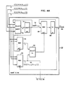
- The two step selection process described mathematically in Figure 3 is apparent in the block diagram of the adaptive predictor, Figure 4. First, both the error count from the previous prediction and the present error signal of each of the predictors is delivered to the adaptive apparatus 60 of Figure 4. In the first step the halftone predictors performance is compared by
selection group 62 and in a separate but simultaneous process the performance of the Bitabove and Prebit predictors is compared byselection group 64. Further inspection reveals that the halftone selection process that takes place inselection group 62 is itself a two-tiered approach more complex than the selection process preformed byselection group 64 and results in the selection of the halftone predictor which had the best performance two bytes previously. At the second step, inselection group 66, the performance of the selected halftone predictor is compared with the performance of the selected nonhalftone predictor. Having determined which predictor performed best on the previous data block,selection group 68 outputs, as the adaptive predictor output, the error code that the selected predictor has generated on the current byte. - The
selection group 62 performs the selection process which is described in Figure 3 by equations A-10 and A-11. The error count of the halftone predictors from the previous data byte are input to selector 70 along with information indicating which of the halftone predictors, had the lowest error count on the previous adaptive cycle,newHT signal 72. Selector 70 compares the respective error counts and selects the lowest) with ties resolved in favor of the halftone predictor previously selected in the comparison or the predictor corresponding to the highest screen frequency as indicated A-11. The output of selector 70 is stored in register 74 at the next adaptive cycle.Signal 72 is referred to in Figure 3 as newHTi-2. (Note in Figure 4 * indicates i-1 and ** indicates i-2). NewHT, signal 72, is input to the select input ofmultiplexor 76 in order to select as the output ofmultiplexor 76 the error count of newHT on the previous byte, signal 78. Signal 78 is compared inselector 80 to signal 82, the error count on the previous byte of the halftone predictor selected on the previous adaptive cycle as ht, signal 84. Ht is referred to in Figure 3 as hti-2.Selector 80 resolves ties in favor of ht and its output indicates which of the two inputs has the lowest error count. The output ofselector 80 is input to the select input ofmultiplexor 86.Multiplexor 86 has as its inputs newHT, signal 72, and ht, signal 84;multiplexor 86 selects one or the other as its output depending on the value of its select input. The output ofmultiplexor 86 is input to register 88 for the next adaptive cycle. The value stored inregister 88 is ht, signal 84. It is the performance of the halftone predictor which has been selected as ht that will be compared to the performance of the selected nonhalftone predictor.Signal 84 is input to the select input ofmultiplexor 89 to select the error count corresponding to ht's performance on the previous byte.Signal 82, the output ofmultiplexor 89, Is output toselection group 66 for comparison with the selected nonhalftone predictor. - The
selection group 64 performs the selection process which is described by Figure 3 equation A-8. The error count of the nonhalftone predictors from the previous byte are input toselector 90 along with information indicating which of the nonhalftone predictors had the lowest error count on the previous adaptive cycle, signal 92.Selector 90 compares the respective error counts and selects the lowest) with ties resolved in favor of the nonhalftone predictor previously selected in the comparison as indicated by Figure 3, equation A-8. The output ofselector 90 is nonHT, signal 94, referred to in Figure 3 as nonHTi-1. NonHT, signal 94, is stored inregister 96 at the next cycle and input to the select input ofmultiplexor 98. This forces the selection of the error count of the predictor selected as nonHT to be the output, signal 100, ofmultiplexor 98.Signal 100 is delivered toselection group 66 for comparison withsignal 82 to determine which predictor is to be used to predict the next data block. NonHT, signal 94, is also delivered toselection group 68 to select the proper error code. - The
selection group 66 performs the selection process which is described in Figure 3 by equation A-9. The error count from the selected halftone predictor, signal 82 and from the selected nonhalftone predictor, signal 100, are input toselector 102 along with information indicating whether a halftone or nonhalftone predictor had been selected on the previous cycle, signal 104.Selector 102 compares the respective error counts and selects the lowest with ties resolved in favor of the predictor of the type selected in the previous cycle. The output ofselector 102, signal 106, is delivered toselection group 68 to select the error code corresponding to the selected signal.Signal 106 is also stored inregister 108 at the next cycle. - The
selection group 68 performs the selection process which is described in Figure 3 by equation A-12. NonHT, signal 94, is input to the select input ofmultiplexor 110 and forces the selection as the output, signal 112, ofmultiplexor 110 the error code of the selected nonhalftone predictor.Signal 112 along with the error code of the selected halftone predictor, which is selected in the same manner as the nonhalftone error code described previously (not shown), signal 114, is input tomultiplexor 116.Signal 106 is input to the select input ofmultiplexor 116 and forces the selection of the error code corresponding to the selected predictor as the output ofmultiplexor 116. This output, signal 118, is the predictor output ready for encoding. - The predictor output can be depredicted into original data by use of the algorithm herein disclosed without the addition of extra address code indicating which of the plurality of predictors was used for encoding. That is, the receiver can determine which depredictor to use by examining past depredictor performance in the manner described above. Furthermore, the circuit herein disclosed does not require additional hardware to buffer the output of the plurality of predictors pending selection of a predictor since the predictor selected for the present block is based on a comparison of performance on the previous block.
Claims (10)
Applications Claiming Priority (2)
| Application Number | Priority Date | Filing Date | Title |
|---|---|---|---|
| US06/540,950 US4559563A (en) | 1983-10-11 | 1983-10-11 | Adaptive prediction for binary encoded documents containing a mixture of text, line drawings and halftones |
| US540950 | 1983-10-11 |
Publications (2)
| Publication Number | Publication Date |
|---|---|
| EP0138529A2 true EP0138529A2 (en) | 1985-04-24 |
| EP0138529A3 EP0138529A3 (en) | 1987-04-22 |
Family
ID=24157569
Family Applications (1)
| Application Number | Title | Priority Date | Filing Date |
|---|---|---|---|
| EP84306809A Withdrawn EP0138529A3 (en) | 1983-10-11 | 1984-10-05 | Adaptive prediction of image data |
Country Status (3)
| Country | Link |
|---|---|
| US (1) | US4559563A (en) |
| EP (1) | EP0138529A3 (en) |
| JP (1) | JPS6096964A (en) |
Cited By (3)
| Publication number | Priority date | Publication date | Assignee | Title |
|---|---|---|---|---|
| EP0444918A2 (en) * | 1990-02-28 | 1991-09-04 | Victor Company Of Japan, Limited | Data compression apparatus |
| EP0504903A2 (en) * | 1991-03-19 | 1992-09-23 | Nec Corporation | Apparatus for and method of preprocessing binary picture data prior to run-length encoding |
| US5542008A (en) * | 1990-02-28 | 1996-07-30 | Victor Company Of Japan, Ltd. | Method of and apparatus for compressing image representing signals |
Families Citing this family (23)
| Publication number | Priority date | Publication date | Assignee | Title |
|---|---|---|---|---|
| US4729034A (en) * | 1985-06-27 | 1988-03-01 | Netexpress Systems, Inc. | Method and apparatus for selection of a coding reference line for two-dimensional coding of image data representing screened images |
| US5099440A (en) * | 1985-12-04 | 1992-03-24 | International Business Machines Corporation | Probability adaptation for arithmetic coders |
| JP2794281B2 (en) * | 1986-07-10 | 1998-09-03 | 株式会社日立製作所 | Code decoding processor for dither signal |
| US4794461A (en) * | 1986-09-10 | 1988-12-27 | Netexpress Systems, Inc. | Method and apparatus for block coding vertical mode codes for enhanced compression of image data |
| GB8708010D0 (en) * | 1987-04-03 | 1987-05-07 | Crosfield Electronics Ltd | Image reprocessing |
| JP2617469B2 (en) * | 1987-05-11 | 1997-06-04 | 株式会社リコー | Image area identification device |
| US4868653A (en) * | 1987-10-05 | 1989-09-19 | Intel Corporation | Adaptive digital video compression system |
| US4811115A (en) * | 1987-10-16 | 1989-03-07 | Xerox Corporation | Image processing apparatus using approximate auto correlation function to detect the frequency of half-tone image data |
| JPH03248674A (en) * | 1990-02-27 | 1991-11-06 | Casio Comput Co Ltd | Half-tone picture processor |
| US5489997A (en) * | 1990-11-27 | 1996-02-06 | Canon Kabushiki Kaisha | Color image processing apparatus |
| US5566255A (en) * | 1991-03-05 | 1996-10-15 | Ricoh Company, Ltd. | Segmenting a page of a document into areas which are text and areas which are halftone |
| JP3276985B2 (en) * | 1991-06-27 | 2002-04-22 | ゼロックス・コーポレーション | Image pixel processing method |
| US5278670A (en) * | 1992-12-18 | 1994-01-11 | Xerox Corporation | Content-based resolution conversion of color documents |
| US5341226A (en) * | 1993-04-22 | 1994-08-23 | Xerox Corporation | Automatic image segmentation for color documents |
| US5327262A (en) * | 1993-05-24 | 1994-07-05 | Xerox Corporation | Automatic image segmentation with smoothing |
| US5339172A (en) * | 1993-06-11 | 1994-08-16 | Xerox Corporation | Apparatus and method for segmenting an input image in one of a plurality of modes |
| US6549656B1 (en) | 1993-11-29 | 2003-04-15 | Xerox Corporation | Fuzzy image segmentation |
| US5509088A (en) * | 1993-12-06 | 1996-04-16 | Xerox Corporation | Method for converting CCITT compressed data using a balanced tree |
| US5758142A (en) * | 1994-05-31 | 1998-05-26 | Digital Equipment Corporation | Trainable apparatus for predicting instruction outcomes in pipelined processors |
| JPH08204971A (en) * | 1994-10-31 | 1996-08-09 | Xerox Corp | Image compression method using predictive coding and error diffusion |
| US5778156A (en) * | 1996-05-08 | 1998-07-07 | Xerox Corporation | Method and system for implementing fuzzy image processing of image data |
| US5765029A (en) * | 1996-05-08 | 1998-06-09 | Xerox Corporation | Method and system for fuzzy image classification |
| US8031954B2 (en) * | 2007-04-26 | 2011-10-04 | Canon Kabushiki Kaisha | Image encoding apparatus and control method thereof using prediction encoding and pixel classification |
Citations (5)
| Publication number | Priority date | Publication date | Assignee | Title |
|---|---|---|---|---|
| US2905756A (en) * | 1956-11-30 | 1959-09-22 | Bell Telephone Labor Inc | Method and apparatus for reducing television bandwidth |
| US4144547A (en) * | 1977-04-04 | 1979-03-13 | Xerox Corporation | Apparatus and method for encoding halftone and line copy data |
| US4215375A (en) * | 1978-02-23 | 1980-07-29 | Nippon Electric Company, Ltd. | Digital facsimile transmission system for screened pictures |
| US4266249A (en) * | 1978-09-19 | 1981-05-05 | Bell Telephone Laboratories, Incorporated | Digital encoder for facsimile transmission |
| EP0066697A1 (en) * | 1981-06-04 | 1982-12-15 | International Business Machines Corporation | A method and system for compressing grey scale image data |
Family Cites Families (6)
| Publication number | Priority date | Publication date | Assignee | Title |
|---|---|---|---|---|
| US3185824A (en) * | 1961-10-24 | 1965-05-25 | Ibm | Adaptive data compactor |
| US3769453A (en) * | 1972-08-17 | 1973-10-30 | Ibm | Finite memory adaptive predictor |
| US3937871A (en) * | 1973-03-26 | 1976-02-10 | International Publishing Corporation Limited | Code communication |
| US4141034A (en) * | 1977-08-19 | 1979-02-20 | Bell Telephone Laboratories, Incorporated | Digital encoding of color video signals |
| US4435726A (en) * | 1980-06-20 | 1984-03-06 | Xerox Corporation | One shot predictor for mixed mode documents |
| JPS5730464A (en) * | 1980-07-30 | 1982-02-18 | Nec Corp | Adaptive forecasting and encoding device |
-
1983
- 1983-10-11 US US06/540,950 patent/US4559563A/en not_active Expired - Lifetime
-
1984
- 1984-10-01 JP JP59204207A patent/JPS6096964A/en active Pending
- 1984-10-05 EP EP84306809A patent/EP0138529A3/en not_active Withdrawn
Patent Citations (5)
| Publication number | Priority date | Publication date | Assignee | Title |
|---|---|---|---|---|
| US2905756A (en) * | 1956-11-30 | 1959-09-22 | Bell Telephone Labor Inc | Method and apparatus for reducing television bandwidth |
| US4144547A (en) * | 1977-04-04 | 1979-03-13 | Xerox Corporation | Apparatus and method for encoding halftone and line copy data |
| US4215375A (en) * | 1978-02-23 | 1980-07-29 | Nippon Electric Company, Ltd. | Digital facsimile transmission system for screened pictures |
| US4266249A (en) * | 1978-09-19 | 1981-05-05 | Bell Telephone Laboratories, Incorporated | Digital encoder for facsimile transmission |
| EP0066697A1 (en) * | 1981-06-04 | 1982-12-15 | International Business Machines Corporation | A method and system for compressing grey scale image data |
Cited By (7)
| Publication number | Priority date | Publication date | Assignee | Title |
|---|---|---|---|---|
| EP0444918A2 (en) * | 1990-02-28 | 1991-09-04 | Victor Company Of Japan, Limited | Data compression apparatus |
| EP0444918A3 (en) * | 1990-02-28 | 1993-06-16 | Victor Company Of Japan, Limited | Data compression apparatus |
| US5542008A (en) * | 1990-02-28 | 1996-07-30 | Victor Company Of Japan, Ltd. | Method of and apparatus for compressing image representing signals |
| US5644658A (en) * | 1990-02-28 | 1997-07-01 | Victor Company Of Japan, Ltd. | Method of and apparatus for compressing image representing signals |
| US5719962A (en) * | 1990-02-28 | 1998-02-17 | Victor Company Of Japan, Ltd. | Method of and apparatus for compressing image representing signals |
| EP0504903A2 (en) * | 1991-03-19 | 1992-09-23 | Nec Corporation | Apparatus for and method of preprocessing binary picture data prior to run-length encoding |
| EP0504903A3 (en) * | 1991-03-19 | 1992-12-02 | Nec Corporation | Arrangement and method of preprocessing binary picture data prior to run-length encoding |
Also Published As
| Publication number | Publication date |
|---|---|
| EP0138529A3 (en) | 1987-04-22 |
| JPS6096964A (en) | 1985-05-30 |
| US4559563A (en) | 1985-12-17 |
Similar Documents
| Publication | Publication Date | Title |
|---|---|---|
| US4559563A (en) | Adaptive prediction for binary encoded documents containing a mixture of text, line drawings and halftones | |
| US4788598A (en) | Coding method and apparatus | |
| US4125861A (en) | Video signal encoding | |
| US5150208A (en) | Encoding apparatus | |
| EP0060694B1 (en) | Apparatus and method for compressing digital data | |
| US6014095A (en) | Variable length encoding system | |
| US4144547A (en) | Apparatus and method for encoding halftone and line copy data | |
| US5539843A (en) | Image processing system | |
| US6310980B1 (en) | Encoding apparatus and method and storage medium | |
| EP0410739B1 (en) | Method and apparatus for compressing halftone image data | |
| US4399467A (en) | Method and apparatus for image data compression and decompression | |
| US5095374A (en) | Method and apparatus for lossless compression and decompression of image data | |
| US4688100A (en) | Video data encoding/decoding apparatus | |
| US5115241A (en) | Predictive coding device with increased resolution | |
| US4366506A (en) | Picture transfer method and apparatus therefor | |
| EP0103773B1 (en) | Method of processing picture signal to increase average run length and apparatus therefor | |
| JPS5831791B2 (en) | Image information band compression transmission device | |
| US5404138A (en) | Apparatus for decoding variable length codes | |
| US4215375A (en) | Digital facsimile transmission system for screened pictures | |
| JPH10294872A (en) | Image coding method, device, image decoding method and device | |
| EP0090140A2 (en) | Complex character generator utilizing byte scanning | |
| US4729034A (en) | Method and apparatus for selection of a coding reference line for two-dimensional coding of image data representing screened images | |
| US4918540A (en) | System for encoding or decoding analog video signals | |
| US3984833A (en) | Apparatus for encoding extended run-length codes | |
| US5929793A (en) | High speed variable length code detection using a cascaded structure |
Legal Events
| Date | Code | Title | Description |
|---|---|---|---|
| PUAI | Public reference made under article 153(3) epc to a published international application that has entered the european phase |
Free format text: ORIGINAL CODE: 0009012 |
|
| AK | Designated contracting states |
Designated state(s): DE FR GB IT |
|
| PUAL | Search report despatched |
Free format text: ORIGINAL CODE: 0009013 |
|
| AK | Designated contracting states |
Kind code of ref document: A3 Designated state(s): DE FR GB IT |
|
| 17P | Request for examination filed |
Effective date: 19871010 |
|
| 17Q | First examination report despatched |
Effective date: 19890719 |
|
| STAA | Information on the status of an ep patent application or granted ep patent |
Free format text: STATUS: THE APPLICATION IS DEEMED TO BE WITHDRAWN |
|
| 18D | Application deemed to be withdrawn |
Effective date: 19891130 |
|
| RIN1 | Information on inventor provided before grant (corrected) |
Inventor name: JOINER, RONALD E., JR. |